EP0401083B1 - Dispositif pour le raccordement étanche d'un tube et d'un tuyau souple - Google Patents
Dispositif pour le raccordement étanche d'un tube et d'un tuyau souple Download PDFInfo
- Publication number
- EP0401083B1 EP0401083B1 EP19900401355 EP90401355A EP0401083B1 EP 0401083 B1 EP0401083 B1 EP 0401083B1 EP 19900401355 EP19900401355 EP 19900401355 EP 90401355 A EP90401355 A EP 90401355A EP 0401083 B1 EP0401083 B1 EP 0401083B1
- Authority
- EP
- European Patent Office
- Prior art keywords
- tube
- ring
- hose
- rigid
- pipe
- Prior art date
- Legal status (The legal status is an assumption and is not a legal conclusion. Google has not performed a legal analysis and makes no representation as to the accuracy of the status listed.)
- Expired - Lifetime
Links
- 230000000295 complement effect Effects 0.000 claims abstract description 16
- 238000007789 sealing Methods 0.000 claims abstract description 10
- 239000004033 plastic Substances 0.000 claims abstract description 7
- 239000000463 material Substances 0.000 claims abstract description 5
- 239000002184 metal Substances 0.000 claims abstract description 5
- 238000006073 displacement reaction Methods 0.000 claims description 2
- 238000004519 manufacturing process Methods 0.000 description 4
- 239000012530 fluid Substances 0.000 description 3
- 238000009434 installation Methods 0.000 description 3
- 230000006835 compression Effects 0.000 description 2
- 238000007906 compression Methods 0.000 description 2
- 238000010276 construction Methods 0.000 description 2
- 239000003292 glue Substances 0.000 description 2
- 238000000034 method Methods 0.000 description 2
- 238000004026 adhesive bonding Methods 0.000 description 1
- 238000001816 cooling Methods 0.000 description 1
- 239000000498 cooling water Substances 0.000 description 1
- 230000006378 damage Effects 0.000 description 1
- 230000006866 deterioration Effects 0.000 description 1
- 230000000694 effects Effects 0.000 description 1
- 239000000446 fuel Substances 0.000 description 1
- 239000007788 liquid Substances 0.000 description 1
- 239000002991 molded plastic Substances 0.000 description 1
- 238000000465 moulding Methods 0.000 description 1
- 230000035515 penetration Effects 0.000 description 1
- 238000000926 separation method Methods 0.000 description 1
- XLYOFNOQVPJJNP-UHFFFAOYSA-N water Substances O XLYOFNOQVPJJNP-UHFFFAOYSA-N 0.000 description 1
Images
Classifications
-
- F—MECHANICAL ENGINEERING; LIGHTING; HEATING; WEAPONS; BLASTING
- F16—ENGINEERING ELEMENTS AND UNITS; GENERAL MEASURES FOR PRODUCING AND MAINTAINING EFFECTIVE FUNCTIONING OF MACHINES OR INSTALLATIONS; THERMAL INSULATION IN GENERAL
- F16L—PIPES; JOINTS OR FITTINGS FOR PIPES; SUPPORTS FOR PIPES, CABLES OR PROTECTIVE TUBING; MEANS FOR THERMAL INSULATION IN GENERAL
- F16L23/00—Flanged joints
-
- F—MECHANICAL ENGINEERING; LIGHTING; HEATING; WEAPONS; BLASTING
- F16—ENGINEERING ELEMENTS AND UNITS; GENERAL MEASURES FOR PRODUCING AND MAINTAINING EFFECTIVE FUNCTIONING OF MACHINES OR INSTALLATIONS; THERMAL INSULATION IN GENERAL
- F16L—PIPES; JOINTS OR FITTINGS FOR PIPES; SUPPORTS FOR PIPES, CABLES OR PROTECTIVE TUBING; MEANS FOR THERMAL INSULATION IN GENERAL
- F16L33/00—Arrangements for connecting hoses to rigid members; Rigid hose-connectors, i.e. single members engaging both hoses
- F16L33/22—Arrangements for connecting hoses to rigid members; Rigid hose-connectors, i.e. single members engaging both hoses with means not mentioned in the preceding groups for gripping the hose between inner and outer parts
-
- F—MECHANICAL ENGINEERING; LIGHTING; HEATING; WEAPONS; BLASTING
- F16—ENGINEERING ELEMENTS AND UNITS; GENERAL MEASURES FOR PRODUCING AND MAINTAINING EFFECTIVE FUNCTIONING OF MACHINES OR INSTALLATIONS; THERMAL INSULATION IN GENERAL
- F16L—PIPES; JOINTS OR FITTINGS FOR PIPES; SUPPORTS FOR PIPES, CABLES OR PROTECTIVE TUBING; MEANS FOR THERMAL INSULATION IN GENERAL
- F16L37/00—Couplings of the quick-acting type
- F16L37/08—Couplings of the quick-acting type in which the connection between abutting or axially overlapping ends is maintained by locking members
- F16L37/084—Couplings of the quick-acting type in which the connection between abutting or axially overlapping ends is maintained by locking members combined with automatic locking
- F16L37/098—Couplings of the quick-acting type in which the connection between abutting or axially overlapping ends is maintained by locking members combined with automatic locking by means of flexible hooks
- F16L37/0985—Couplings of the quick-acting type in which the connection between abutting or axially overlapping ends is maintained by locking members combined with automatic locking by means of flexible hooks the flexible hook extending radially inwardly from an outer part and engaging a bead, recess or the like on an inner part
-
- Y—GENERAL TAGGING OF NEW TECHNOLOGICAL DEVELOPMENTS; GENERAL TAGGING OF CROSS-SECTIONAL TECHNOLOGIES SPANNING OVER SEVERAL SECTIONS OF THE IPC; TECHNICAL SUBJECTS COVERED BY FORMER USPC CROSS-REFERENCE ART COLLECTIONS [XRACs] AND DIGESTS
- Y10—TECHNICAL SUBJECTS COVERED BY FORMER USPC
- Y10S—TECHNICAL SUBJECTS COVERED BY FORMER USPC CROSS-REFERENCE ART COLLECTIONS [XRACs] AND DIGESTS
- Y10S285/00—Pipe joints or couplings
- Y10S285/906—Equivalents
-
- Y—GENERAL TAGGING OF NEW TECHNOLOGICAL DEVELOPMENTS; GENERAL TAGGING OF CROSS-SECTIONAL TECHNOLOGIES SPANNING OVER SEVERAL SECTIONS OF THE IPC; TECHNICAL SUBJECTS COVERED BY FORMER USPC CROSS-REFERENCE ART COLLECTIONS [XRACs] AND DIGESTS
- Y10—TECHNICAL SUBJECTS COVERED BY FORMER USPC
- Y10S—TECHNICAL SUBJECTS COVERED BY FORMER USPC CROSS-REFERENCE ART COLLECTIONS [XRACs] AND DIGESTS
- Y10S285/00—Pipe joints or couplings
- Y10S285/915—Mastic
Definitions
- connection is made between a rigid tube, generally metallic or made of plastic, and a hose made of rubber or other flexible and elastically deformable material; both have a substantially circular cross section.
- the flexible hose is force fitted on one end of a rigid tube, sometimes formed by a simple end piece, molded during the manufacture of a motor housing, or forming a single piece with an apparatus, such as for example a cooling radiator. After fitting the flexible hose onto the rigid tube, the tightness of the connection and the securing of the hose to the tube are simultaneously ensured by a hose clamp.
- Patent application GB-A-2,161,568 describes an assembly of the kind which has just been exposed, although a clamping ring with longitudinal strips is provided, between the flexible pipe and the clamp. A similar construction is proposed by the published European application 0 219 418.
- connection device it is essential that two sealing zones are formed, on the one hand, between the flexible pipe element and the corresponding end piece, on the other hand, between the two complementary tips.
- patent FR-A-909,769 and patent US-A-2,853,320 describe connection devices in which a ring disposed outside the flexible pipe has at least one internal shoulder.
- the invention therefore relates to a removable device for tight and rapid connection of a flexible pipe fitted on a cylindrical tube, smooth and rigid, the outside diameter of which is greater than the inside diameter of the flexible pipe.
- Such a device comprises a rigid ring made of metal or semi-rigid plastic, disposed outside the flexible pipe and coaxial to it, said ring having, over most of its length, a single internal cylindrical portion, the internal diameter is substantially equal to the external diameter of the flexible pipe and an annular groove defining an internal shoulder intended to constitute an axial stop for the external surface of the pipe; on the other hand, additional axial attachment means are linked respectively to the rigid ring and to the tube.
- the rigid ring is fixed by gluing to the flexible pipe before the flexible pipe is fitted onto the rigid tube by a simple axial displacement, in a position such that the free end of the flexible pipe is located inside the ring , opposite its annular groove and beyond the internal shoulder, while the bottom of the annular groove has a diameter greater than at least twice the thickness of the flexible pipe, than the outside diameter of the tube, so that, after axial assembly of the complementary means, the axial stop alone ensures, by pinching the wall of the flexible pipe, the support of two unique complementary sealing surfaces of the tube and the inner surface of the pipe.
- the device according to the invention is perfectly compatible with complete automation of the installation of the connection.
- the connection is obtained without exerting significant radial forces on the flexible pipe, which avoids the risks of creep and the leaks which could result therefrom.
- the establishment of a connection requires only the axial approximation of the tube and the flexible pipe, an operation which can be automated.
- the continuation of the axial movement can immediately cause the cooperation of the complementary attachment means.
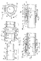
- a device for connecting a rigid tube 1 for example of metal or plastic, and a flexible pipe 2 , such as 'a rubber "hose". It essentially comprises, on the one hand, a ring 3 , for example made of molded plastic, placed outside the flexible pipe 2 , on the other hand, additional means for axial attachment, designated by the general reference 4 , linked respectively to the ring 3 and to the tube 1 .
- the tube 1 and the pipe 2 have circular sections, preferably similar, the outside diameter D of the pipe 1 being however slightly greater than the inside diameter D ' of the pipe 2 .
- the free end of the tube 1 has a chamfer 1 a which is followed by a cylindrical part 1 b whose outside diameter is substantially equal and, preferably, at most equal to the inside diameter D 'of the pipe 2 .
- This cylindrical part 1b advantageously extends over a certain length which will be specified below.
- the external surface of the tube has a second cylindrical part 1 f whose external diameter D is, as already indicated, a slightly greater than the internal diameter D ' of the pipe 2 and which is connected to the cylindrical part 1 b by a simple chamfer 1 g .
- the latter therefore constitutes a frustoconical portion, located in the vicinity of the free end of the tube 1 , unless it is the very end of the tube in the case where the cylindrical portion 1b does not exist. It is important to note that the largest diameter of this frustoconical portion is equal to the outside diameter D of the tube, while its smallest diameter is itself at most equal to the diameter D ′ of the pipe.
- the tube 1 has a radial flange 1 d , projecting outwards, its face 1 e opposite the end 1 a constituting a shoulder whose utility will appear more far.
- the ring 3 has on its internal face a cylindrical portion 3 a whose inside diameter is substantially equal to the outside diameter of the pipe 2 on which it is to be mounted.
- the length of the cylindrical portion 1b of the tube is sufficient to extend, after assembly, facing at least a fraction of the cylindrical portion 3a of the ring.
- the inner surface is preferable smooth leave 3a of the ring 3.
- the inlet end (on the right in FIG. 1) of the ring 3 is preferably chamfered, while its opposite end has an annular shoulder 3 d whose internal diameter is close to the external diameter D of the cylindrical part 1 f of tube 1 .
- legs 5 radially flexible, extend parallel to the axis of the ring which will become, after fitting, the common axis of the tube 1 and the pipe 2 .
- these legs are three in number.
- the free end of each of them is in the form of a hook 5 a , capable of snapping onto the shoulder 1 e of the collar 1 d of the tube.
- the tabs 5 Free, between the connection area to the ring 3 and the hook 5 a , the tabs 5 have a cylindrical internal face 5 c parallel to the axis of the ring.
- a ring 6 coaxial with the ring and provided with a sleeve 6 e , can be disposed between the tabs 5 before the fitting is put in place, the ring and its sleeve sliding between the shoulder 3 d of the ring and the hooks 5 has legs.
- the inside diameter of the sleeve 6 e is substantially equal to the outside diameter D of the cylindrical part 1 f of the tube 1 , while its length is close to that of the legs, reduced by the thickness of the collar 1 d .
- the outer periphery of the ring 6 advantageously has the shape of a cam 6 c , in contact with the inner face 5 c of the legs, ending in a gripping fin 6 d (FIG. 2).
- annular groove 3 e is provided between the shoulder 3 d and the cylindrical portion 3 a of the ring, the cylindrical bottom 3 f of which causes the appearance of a sharp edge 3 g at the connection of the cylindrical portion. 3 a and from the side 3 h of the throat 3 e .
- connection of the tube and the hose is carried out as follows.
- tube 1 and hose 2 For the connection of tube 1 and hose 2 , this thereof, provided with the ring 3, is presented opposite the end 1a without the need to ensure a specific orientation about its axis.
- Relative axial movement of the pipe 2 to the tube 1 allows the end 1a from entering the pipe.
- the sleeve 6 e optionally facilitates guiding and centering the end of the tube 1 , which can be important if it is desired to automate this operation.
- the wall of the pipe offers practically no resistance to the penetration of the cylindrical part 1 b , but when the frustoconical portion 1 g of the tube meets the free end of the pipe 2 , the latter is pushed back radially into the housing constituted by the groove 3 e ( Figure 3).
- the free end of the pipe is simply pushed back into the housing consisting mainly of the groove 3 e ; it should even be avoided that this free end is compressed in the groove 3 e .
- the diameter of the bottom 3 f of the groove will advantageously be at least twice the thickness of the flexible pipe, to the largest diameter D of the frustoconical portion 1 g of the tube.
- the distance d between the face 1 e of the flange 1 d and the start of the chamfer 1 g is at most equal, and preferably substantially less than the distance from between the face support hooks 5 a and the beginning 3 g of the cylindrical portion 3 a of the ring.
- the axial dislocation of the tube 1 and the ring is obviously prevented by the attachment means 4 .
- the flexible pipe 2 is strongly anchored in the groove 3 e of the ring, due to the constriction produced by the opposite zones, the edge 3 g and the frustoconical portion 1 g .
- the effectiveness of the throttling will generally be improved by the fact that the cylindrical portion 1b of the tube extends over at least a fraction of the cylindrical portion 3a of the ring.
- the ring 6 is rotated on the tube 1 in the direction of arrow F in FIG. 2 to bring each fin 6 d in the vicinity of the front tab 5 .
- the legs 5 are raised to reach the visible position in dotted lines in Figures 2 and 3, thereby releasing the hooks 5 a from the flange 1 d .
- a pull on the pipe 2 in the direction of the arrow F1 then makes it possible to disengage it from the tube 1 .
- the number of parts necessary for the production of the device is reduced and they do not require very precise manufacture.
- the cost of the device is therefore low.
- the axial force for fitting the tube 1 into the pipe 2 until it is locked may itself be low, for example of the order of 200 newtons for a pipe diameter close to 40 mm, if the fluid pressure carried is less than 10 bar.
- the legs 15 are linked to the tube 11 and are preferably molded with it. They have hooks 15 a which snap behind the ring 13 at the end of the connection operation, the edge 13 j of the ring playing a role similar to that of the face 1 e of the flange 1 d .
- the unlocking ring 16 and its sleeve 16 e have been shown diagrammatically; they will preferably be of the type already described in connection with the previous embodiment. It is the same for the throat 13 e and the shoulder 13 d : on the tube 11 , there corresponds a frustoconical portion 11 g whose external diameter pushes the wall of the pipe 12 in the throat 13 e while pinching it against the edge 13 g .
- the axial attachment means are all of the same type, it is possible to use complementary members of another type, for example those commonly called “bayonet mounting".
- the latter in particular, are perfectly suited to fully automated installation.
- they generally make it possible to provide only one piece for ensuring both the connection of the tube and the hose and their disassembly.
Landscapes
- Engineering & Computer Science (AREA)
- General Engineering & Computer Science (AREA)
- Mechanical Engineering (AREA)
- Quick-Acting Or Multi-Walled Pipe Joints (AREA)
- Joints That Cut Off Fluids, And Hose Joints (AREA)
- Examining Or Testing Airtightness (AREA)
- Pipe Accessories (AREA)
- Mechanical Coupling Of Light Guides (AREA)
- Cable Accessories (AREA)
- Manipulator (AREA)
Applications Claiming Priority (2)
| Application Number | Priority Date | Filing Date | Title |
|---|---|---|---|
| FR8907021 | 1989-05-29 | ||
| FR8907021 | 1989-05-29 |
Publications (2)
| Publication Number | Publication Date |
|---|---|
| EP0401083A1 EP0401083A1 (fr) | 1990-12-05 |
| EP0401083B1 true EP0401083B1 (fr) | 1993-11-10 |
Family
ID=9382108
Family Applications (1)
| Application Number | Title | Priority Date | Filing Date |
|---|---|---|---|
| EP19900401355 Expired - Lifetime EP0401083B1 (fr) | 1989-05-29 | 1990-05-22 | Dispositif pour le raccordement étanche d'un tube et d'un tuyau souple |
Country Status (14)
| Country | Link |
|---|---|
| US (1) | US5131687A (pt) |
| EP (1) | EP0401083B1 (pt) |
| JP (1) | JPH0374695A (pt) |
| KR (1) | KR900018583A (pt) |
| AT (1) | ATE97215T1 (pt) |
| BR (1) | BR9002450A (pt) |
| CA (1) | CA2017398A1 (pt) |
| CS (1) | CS277632B6 (pt) |
| DE (1) | DE69004490T2 (pt) |
| DK (1) | DK0401083T3 (pt) |
| ES (1) | ES2047873T3 (pt) |
| PL (1) | PL163639B1 (pt) |
| PT (1) | PT8341U (pt) |
| RU (1) | RU2037723C1 (pt) |
Families Citing this family (43)
| Publication number | Priority date | Publication date | Assignee | Title |
|---|---|---|---|---|
| FR2672959B1 (fr) * | 1991-02-20 | 1993-06-11 | Attax | Dispositif de fixation d'un organe tubulaire sur un embout tubulaire de raccordement d'un composant, notamment de vehicule automobile. |
| US5257739A (en) * | 1992-05-13 | 1993-11-02 | Pascaru Michael J | Riser for industrial pretreatment washers |
| US5388873A (en) * | 1993-06-18 | 1995-02-14 | Metcal, Inc. | Coupling device useful for joining or capping plastic pipe |
| US5547232A (en) * | 1993-10-12 | 1996-08-20 | Carrier Corporation | Reusable sealed coupling for two pipes |
| US5367548A (en) * | 1994-03-15 | 1994-11-22 | B&W Fuel Company | Guide tube retainer |
| US5361283A (en) * | 1994-03-15 | 1994-11-01 | B&W Fuel Company | Guide tube retainer |
| US5779279A (en) * | 1994-05-24 | 1998-07-14 | Proprietary Technology, Inc. | Connection verification and secondary latch device |
| DE19622099A1 (de) * | 1996-06-01 | 1997-12-04 | Behr Gmbh & Co | Schnellkupplung für eine Kühlmittelleitung |
| DE19637276A1 (de) * | 1996-09-13 | 1998-03-19 | Bosch Gmbh Robert | Kraftstoffördereinrichtung für Kraftfahrzeuge |
| US5931509A (en) * | 1996-11-19 | 1999-08-03 | Proprietary Technology, Inc. | Connection verification and secondary latch device |
| JP3938798B2 (ja) * | 1996-11-20 | 2007-06-27 | 臼井国際産業株式会社 | 細径配管接続用コネクター |
| FR2769350B1 (fr) * | 1997-10-02 | 1999-12-24 | Sofigaz | Procede et installation pour raccorder un tuyau souple et un embout tubulaire et dispositif de raccordement entre un tuyau souple et un embout tubulaire |
| FR2776747B1 (fr) * | 1998-03-27 | 2000-06-02 | Hutchinson | Raccord encliquetable pour tuyau de transfert de fluide |
| US6115440A (en) * | 1998-04-29 | 2000-09-05 | Westinghouse Electric Company Llc | Quick release, removable top nozzle assembly |
| DE19858396A1 (de) * | 1998-12-17 | 2000-07-06 | Duerr Systems Gmbh | Schlauchverbinder |
| US6257626B1 (en) | 1999-04-27 | 2001-07-10 | Flow-Rite Controls, Ltd. | Connector for fluid handling system |
| US6186559B1 (en) | 1999-12-22 | 2001-02-13 | Visteon Global Technologies, Inc. | Tube coupling assembly |
| US6453539B1 (en) | 2000-04-12 | 2002-09-24 | Dana Corporation | Metal tube coupling arrangement and method of manufacture |
| US7185921B2 (en) * | 2002-06-28 | 2007-03-06 | Nestec S.A. | Hose fitment for disposable food container |
| FR2848283B1 (fr) * | 2002-12-09 | 2007-01-05 | Renault Sa | Embout male encliquetable pour raccord de tuyau de transfert de fluide |
| US20050104374A1 (en) * | 2003-11-17 | 2005-05-19 | Steur Gunnar V.D. | Pull-out resistant compression fitting for fluid lines |
| JP4120571B2 (ja) * | 2003-11-25 | 2008-07-16 | 株式会社デンソー | 配管継手装置 |
| DE102005006330B4 (de) * | 2005-01-12 | 2009-11-12 | Norma Germany Gmbh | Kupplung zum Verbinden zweier Rohre |
| FR2881811B1 (fr) * | 2005-02-10 | 2007-04-20 | Legris Sa | Dispositif de raccordement instantane avec moyen de verrouillage et/ou de deconnexion |
| US7658420B2 (en) * | 2006-07-13 | 2010-02-09 | Parker-Hannifin Corporation | Quick-connect fitting with unlocking ring |
| WO2008111514A1 (ja) * | 2007-03-12 | 2008-09-18 | Sanoh Kogyo Kabushiki Kaisha | 樹脂チューブの接続構造 |
| US20090058082A1 (en) * | 2007-09-05 | 2009-03-05 | Green Ronald D | Two-part quick connect retention attachment for flexible tubing in a water supply system |
| US7878556B2 (en) * | 2008-03-03 | 2011-02-01 | Adroit Development, Inc. | Safety release adapter |
| JP5306868B2 (ja) * | 2009-03-23 | 2013-10-02 | 株式会社ニフコ | パイプ連結用コネクタ |
| DE102009020577A1 (de) * | 2009-05-09 | 2010-11-11 | Muhr Und Bender Kg | Steckverbindungsanordnung |
| DE102010010522B4 (de) | 2010-03-05 | 2012-10-25 | Voss Automotive Gmbh | Steckverbinder für Medienleitungen |
| CN102312904B (zh) * | 2010-07-07 | 2013-06-12 | 南通瑞和船舶配件有限公司 | 带内加强环型缠绕式垫片的组装方法 |
| WO2012008953A1 (en) * | 2010-07-14 | 2012-01-19 | Hewlett-Packard Development Company L.P. | Mounting apparatus and system thereof |
| CA3033380A1 (en) | 2011-12-09 | 2013-06-09 | Mercury Plastics Llc | Quick-connect tube coupling |
| US9925350B2 (en) | 2013-02-19 | 2018-03-27 | Fisher & Paykel Healthcare Limited | Apparatus and method for providing gases to a user |
| NO336211B1 (no) * | 2013-04-22 | 2015-06-15 | Kongsberg Esco As | Låseanordning for rør |
| JP6216210B2 (ja) * | 2013-10-25 | 2017-10-18 | 株式会社ニフコ | ホースコネクタ |
| FR3060069B1 (fr) * | 2016-12-13 | 2019-05-24 | Airbus Operations Sas | Bielle amortissante convertible en bielle rigide |
| US10718453B2 (en) | 2017-11-21 | 2020-07-21 | Flexible Technologies, Inc. | Flexible hose with improved over-molded cuffs and methods of making same |
| CN110081252A (zh) * | 2019-05-27 | 2019-08-02 | 程思哲 | 一种柔性管道接口和消力管道 |
| US11898676B2 (en) | 2020-05-13 | 2024-02-13 | Mercury Plastics Llc | Quick-connect fitting |
| CN113236253B (zh) * | 2021-05-28 | 2023-04-28 | 辽宁科技大学 | 一种无底柱分段崩落法远距离自动折管覆盖岩注浆方法 |
| CN115523723B (zh) * | 2022-09-16 | 2024-05-17 | 中国矿业大学 | 一种低阶煤的离心热载气联合脱水方法 |
Citations (1)
| Publication number | Priority date | Publication date | Assignee | Title |
|---|---|---|---|---|
| US2853320A (en) * | 1954-09-27 | 1958-09-23 | S & C Mfg Co | Screw thimble-compressed type fitting for flexible plastic tubing |
Family Cites Families (11)
| Publication number | Priority date | Publication date | Assignee | Title |
|---|---|---|---|---|
| DE530957C (de) * | 1929-09-22 | 1931-08-03 | Pleiger Paul | Schlauchverbindung |
| US1903445A (en) * | 1930-10-11 | 1933-04-11 | Ernst Clemens Joseph | Hose and pipe coupling |
| FR909769A (fr) * | 1944-10-23 | 1946-05-17 | Raccord perfectionné pour tuyaux flexibles | |
| CH338063A (de) * | 1955-07-23 | 1959-04-30 | J S Schatt Gmbh Armaturenfabri | Rohrverschraubung für Kunststoffrohre |
| FR1249979A (fr) * | 1959-11-24 | 1961-01-06 | Etablissements G Boutin Soc D | Raccord de tuyau renforcé pour hautes pressions et son procédé de mise en oeuvre |
| GB1034622A (en) * | 1963-09-04 | 1966-06-29 | Anton Biechele | Improvements in hose couplings |
| GB1065325A (en) * | 1963-10-15 | 1967-04-12 | Btr Industries Ltd | Improvements in or relating to hose end fittings |
| US3262721A (en) * | 1964-05-01 | 1966-07-26 | Nelson Mfg Co Inc L R | Snap action hose fitting |
| DE3444817A1 (de) * | 1984-01-20 | 1985-07-25 | Rasmussen Gmbh, 6457 Maintal | Steckkupplung |
| DE3424675C2 (de) * | 1984-07-05 | 1986-10-16 | Rasmussen Gmbh, 6457 Maintal | Schlauchkupplung |
| FR2628819B1 (fr) * | 1988-03-17 | 1990-07-20 | Peugeot | Dispositif de jonction entre un raccord tubulaire souple et un embout tubulaire rigide |
-
1990
- 1990-05-22 US US07/526,834 patent/US5131687A/en not_active Expired - Fee Related
- 1990-05-22 EP EP19900401355 patent/EP0401083B1/fr not_active Expired - Lifetime
- 1990-05-22 AT AT90401355T patent/ATE97215T1/de not_active IP Right Cessation
- 1990-05-22 DK DK90401355.4T patent/DK0401083T3/da active
- 1990-05-22 ES ES90401355T patent/ES2047873T3/es not_active Expired - Lifetime
- 1990-05-22 DE DE69004490T patent/DE69004490T2/de not_active Expired - Fee Related
- 1990-05-23 CA CA002017398A patent/CA2017398A1/en not_active Abandoned
- 1990-05-24 BR BR909002450A patent/BR9002450A/pt unknown
- 1990-05-28 JP JP2138154A patent/JPH0374695A/ja active Pending
- 1990-05-28 PL PL90285373A patent/PL163639B1/pl unknown
- 1990-05-28 RU SU904830029A patent/RU2037723C1/ru active
- 1990-05-29 KR KR1019900007780A patent/KR900018583A/ko not_active Withdrawn
- 1990-05-29 CS CS902642A patent/CS277632B6/cs unknown
-
1991
- 1991-09-05 PT PT8341U patent/PT8341U/pt not_active IP Right Cessation
Patent Citations (1)
| Publication number | Priority date | Publication date | Assignee | Title |
|---|---|---|---|---|
| US2853320A (en) * | 1954-09-27 | 1958-09-23 | S & C Mfg Co | Screw thimble-compressed type fitting for flexible plastic tubing |
Also Published As
| Publication number | Publication date |
|---|---|
| DE69004490D1 (de) | 1993-12-16 |
| CS277632B6 (en) | 1993-03-17 |
| DE69004490T2 (de) | 1994-05-26 |
| ES2047873T3 (es) | 1994-03-01 |
| DK0401083T3 (da) | 1994-04-25 |
| PL163639B1 (pl) | 1994-04-29 |
| PT8341U (pt) | 1995-03-01 |
| EP0401083A1 (fr) | 1990-12-05 |
| PT8341T (pt) | 1992-02-28 |
| ATE97215T1 (de) | 1993-11-15 |
| RU2037723C1 (ru) | 1995-06-19 |
| JPH0374695A (ja) | 1991-03-29 |
| US5131687A (en) | 1992-07-21 |
| CA2017398A1 (en) | 1990-11-29 |
| CS264290A3 (en) | 1992-04-15 |
| BR9002450A (pt) | 1991-08-06 |
| KR900018583A (ko) | 1990-12-22 |
| PL285373A1 (en) | 1991-01-14 |
Similar Documents
| Publication | Publication Date | Title |
|---|---|---|
| EP0401083B1 (fr) | Dispositif pour le raccordement étanche d'un tube et d'un tuyau souple | |
| EP0511891B1 (fr) | Elément de connexion pour le raccordement rapide d'un tube | |
| EP0440564B1 (fr) | Dispositif de raccordement d'un tuyau souple sur un embout tubulaire rigide | |
| FR2942650A1 (fr) | Dispositif de couplage de connexion rapide | |
| FR2649176A1 (fr) | Garniture d'etancheite pour joints verrouilles etanches | |
| EP2878873A1 (fr) | Dispositif de raccordement rapide de type cartouche | |
| FR2663080A1 (fr) | Ensemble formant raccord d'accouplement pour circuits de refrigerant de moteur de vehicule. | |
| FR2588354A1 (fr) | Dispositif de raccordement d'un tuyau elastiquement deformable a un tube rigide | |
| FR2790058A1 (fr) | Dispositif d'obturation de l'extremite d'un tuyau | |
| EP2162663B1 (fr) | Raccord a lavage exterieur facilite | |
| FR2679313A1 (fr) | Dispositif de serrage etanche pour le serrage d'un tube flexible monte a force a l'interieur d'un raccord tubulaire. | |
| FR2584472A1 (fr) | Accouplement emboitable pour accoupler un flexible ou organe analogue a un raccord tubulaire | |
| FR2868500A1 (fr) | Connecteur rapide | |
| EP0737830A1 (fr) | Joint et son procédé de montage | |
| EP0627592B1 (fr) | Connexion rapide | |
| BE1008705A3 (fr) | Raccord de fixation pour un tube annele. | |
| EP0327441B1 (fr) | Echangeur de chaleur | |
| EP0371829B1 (fr) | Embout pour le raccordement rapide d'un tube | |
| FR2772875A1 (fr) | Dispositif de raccordement d'un tuyau souple a une paroi, en particulier d'un echangeur de chaleur de vehicule automobile | |
| FR2578621A1 (fr) | Dispositif de raccordement amovible pour tuyaux | |
| FR2602572A1 (fr) | Dispositif de raccordement d'un tuyau souple autour d'un embout tubulaire rigide | |
| FR2496220A1 (fr) | Raccord a emboitement et son procede de montage | |
| EP0327442A1 (fr) | Dispositif d'assemblage pour un ensemble échangeur de chaleur/raccord tubulaire | |
| EP0469999B1 (fr) | Procédé de raccordement étanche et raccord étanche correspondant | |
| EP0549503B1 (fr) | Manchon de liaison et son procédé de montage |
Legal Events
| Date | Code | Title | Description |
|---|---|---|---|
| PUAI | Public reference made under article 153(3) epc to a published international application that has entered the european phase |
Free format text: ORIGINAL CODE: 0009012 |
|
| AK | Designated contracting states |
Kind code of ref document: A1 Designated state(s): AT BE CH DE DK ES FR GB GR IT LI LU NL SE |
|
| 17P | Request for examination filed |
Effective date: 19910417 |
|
| 17Q | First examination report despatched |
Effective date: 19920122 |
|
| GRAA | (expected) grant |
Free format text: ORIGINAL CODE: 0009210 |
|
| AK | Designated contracting states |
Kind code of ref document: B1 Designated state(s): AT BE CH DE DK ES FR GB GR IT LI LU NL SE |
|
| REF | Corresponds to: |
Ref document number: 97215 Country of ref document: AT Date of ref document: 19931115 Kind code of ref document: T |
|
| REF | Corresponds to: |
Ref document number: 69004490 Country of ref document: DE Date of ref document: 19931216 |
|
| ITF | It: translation for a ep patent filed | ||
| RAP4 | Party data changed (patent owner data changed or rights of a patent transferred) |
Owner name: AUTOBREVETS |
|
| REG | Reference to a national code |
Ref country code: ES Ref legal event code: FG2A Ref document number: 2047873 Country of ref document: ES Kind code of ref document: T3 |
|
| GBT | Gb: translation of ep patent filed (gb section 77(6)(a)/1977) |
Effective date: 19940203 |
|
| PGFP | Annual fee paid to national office [announced via postgrant information from national office to epo] |
Ref country code: AT Payment date: 19940421 Year of fee payment: 5 |
|
| REG | Reference to a national code |
Ref country code: DK Ref legal event code: T3 |
|
| REG | Reference to a national code |
Ref country code: GR Ref legal event code: FG4A Free format text: 3010692 |
|
| PGFP | Annual fee paid to national office [announced via postgrant information from national office to epo] |
Ref country code: SE Payment date: 19940519 Year of fee payment: 5 |
|
| PGFP | Annual fee paid to national office [announced via postgrant information from national office to epo] |
Ref country code: GR Payment date: 19940524 Year of fee payment: 5 |
|
| PGFP | Annual fee paid to national office [announced via postgrant information from national office to epo] |
Ref country code: NL Payment date: 19940531 Year of fee payment: 5 |
|
| PGFP | Annual fee paid to national office [announced via postgrant information from national office to epo] |
Ref country code: DK Payment date: 19940630 Year of fee payment: 5 |
|
| PLBE | No opposition filed within time limit |
Free format text: ORIGINAL CODE: 0009261 |
|
| STAA | Information on the status of an ep patent application or granted ep patent |
Free format text: STATUS: NO OPPOSITION FILED WITHIN TIME LIMIT |
|
| EPTA | Lu: last paid annual fee | ||
| 26N | No opposition filed | ||
| EAL | Se: european patent in force in sweden |
Ref document number: 90401355.4 |
|
| PG25 | Lapsed in a contracting state [announced via postgrant information from national office to epo] |
Ref country code: DK Effective date: 19950522 Ref country code: AT Effective date: 19950522 |
|
| REG | Reference to a national code |
Ref country code: DK Ref legal event code: EBP |
|
| PG25 | Lapsed in a contracting state [announced via postgrant information from national office to epo] |
Ref country code: SE Effective date: 19950523 |
|
| PG25 | Lapsed in a contracting state [announced via postgrant information from national office to epo] |
Ref country code: GR Free format text: THE PATENT HAS BEEN ANNULLED BY A DECISION OF A NATIONAL AUTHORITY Effective date: 19951130 |
|
| PG25 | Lapsed in a contracting state [announced via postgrant information from national office to epo] |
Ref country code: NL Effective date: 19951201 |
|
| REG | Reference to a national code |
Ref country code: GR Ref legal event code: MM2A Free format text: 3010692 |
|
| NLV4 | Nl: lapsed or anulled due to non-payment of the annual fee |
Effective date: 19951201 |
|
| EUG | Se: european patent has lapsed |
Ref document number: 90401355.4 |
|
| PGFP | Annual fee paid to national office [announced via postgrant information from national office to epo] |
Ref country code: GB Payment date: 19970516 Year of fee payment: 8 Ref country code: ES Payment date: 19970516 Year of fee payment: 8 |
|
| PGFP | Annual fee paid to national office [announced via postgrant information from national office to epo] |
Ref country code: DE Payment date: 19970623 Year of fee payment: 8 |
|
| PGFP | Annual fee paid to national office [announced via postgrant information from national office to epo] |
Ref country code: CH Payment date: 19970624 Year of fee payment: 8 |
|
| PGFP | Annual fee paid to national office [announced via postgrant information from national office to epo] |
Ref country code: LU Payment date: 19970707 Year of fee payment: 8 |
|
| PGFP | Annual fee paid to national office [announced via postgrant information from national office to epo] |
Ref country code: BE Payment date: 19970711 Year of fee payment: 8 |
|
| REG | Reference to a national code |
Ref country code: FR Ref legal event code: TP |
|
| PG25 | Lapsed in a contracting state [announced via postgrant information from national office to epo] |
Ref country code: LU Free format text: LAPSE BECAUSE OF NON-PAYMENT OF DUE FEES Effective date: 19980522 Ref country code: GB Free format text: LAPSE BECAUSE OF NON-PAYMENT OF DUE FEES Effective date: 19980522 |
|
| PG25 | Lapsed in a contracting state [announced via postgrant information from national office to epo] |
Ref country code: ES Free format text: LAPSE BECAUSE OF EXPIRATION OF PROTECTION Effective date: 19980523 |
|
| PG25 | Lapsed in a contracting state [announced via postgrant information from national office to epo] |
Ref country code: LI Free format text: LAPSE BECAUSE OF NON-PAYMENT OF DUE FEES Effective date: 19980531 Ref country code: CH Free format text: LAPSE BECAUSE OF NON-PAYMENT OF DUE FEES Effective date: 19980531 Ref country code: BE Free format text: LAPSE BECAUSE OF NON-PAYMENT OF DUE FEES Effective date: 19980531 |
|
| BERE | Be: lapsed |
Owner name: AUTOBREVETS Effective date: 19980531 |
|
| GBPC | Gb: european patent ceased through non-payment of renewal fee |
Effective date: 19980522 |
|
| REG | Reference to a national code |
Ref country code: CH Ref legal event code: PL |
|
| PG25 | Lapsed in a contracting state [announced via postgrant information from national office to epo] |
Ref country code: DE Free format text: LAPSE BECAUSE OF NON-PAYMENT OF DUE FEES Effective date: 19990302 |
|
| REG | Reference to a national code |
Ref country code: ES Ref legal event code: FD2A Effective date: 20000601 |
|
| PGFP | Annual fee paid to national office [announced via postgrant information from national office to epo] |
Ref country code: FR Payment date: 20030228 Year of fee payment: 14 |
|
| PG25 | Lapsed in a contracting state [announced via postgrant information from national office to epo] |
Ref country code: FR Free format text: LAPSE BECAUSE OF NON-PAYMENT OF DUE FEES Effective date: 20050131 |
|
| REG | Reference to a national code |
Ref country code: FR Ref legal event code: ST |
|
| PG25 | Lapsed in a contracting state [announced via postgrant information from national office to epo] |
Ref country code: IT Free format text: LAPSE BECAUSE OF NON-PAYMENT OF DUE FEES;WARNING: LAPSES OF ITALIAN PATENTS WITH EFFECTIVE DATE BEFORE 2007 MAY HAVE OCCURRED AT ANY TIME BEFORE 2007. THE CORRECT EFFECTIVE DATE MAY BE DIFFERENT FROM THE ONE RECORDED. Effective date: 20050522 |