EP0399650A2 - Keilförmige prismatische Anordnung zur optischen Informatonsspeicherung - Google Patents
Keilförmige prismatische Anordnung zur optischen Informatonsspeicherung Download PDFInfo
- Publication number
- EP0399650A2 EP0399650A2 EP90304136A EP90304136A EP0399650A2 EP 0399650 A2 EP0399650 A2 EP 0399650A2 EP 90304136 A EP90304136 A EP 90304136A EP 90304136 A EP90304136 A EP 90304136A EP 0399650 A2 EP0399650 A2 EP 0399650A2
- Authority
- EP
- European Patent Office
- Prior art keywords
- optical
- prism
- assembly
- light beam
- plane
- Prior art date
- Legal status (The legal status is an assumption and is not a legal conclusion. Google has not performed a legal analysis and makes no representation as to the accuracy of the status listed.)
- Granted
Links
- 230000003287 optical effect Effects 0.000 title claims abstract description 111
- 238000000576 coating method Methods 0.000 claims description 11
- 239000011248 coating agent Substances 0.000 claims description 5
- 230000008878 coupling Effects 0.000 claims 1
- 238000010168 coupling process Methods 0.000 claims 1
- 238000005859 coupling reaction Methods 0.000 claims 1
- 230000000712 assembly Effects 0.000 abstract description 8
- 238000000429 assembly Methods 0.000 abstract description 8
- 239000010409 thin film Substances 0.000 abstract description 7
- 239000004568 cement Substances 0.000 abstract description 4
- 230000006870 function Effects 0.000 abstract description 4
- 230000005381 magnetic domain Effects 0.000 description 6
- 230000010287 polarization Effects 0.000 description 6
- 230000005540 biological transmission Effects 0.000 description 4
- 230000000295 complement effect Effects 0.000 description 4
- 238000010586 diagram Methods 0.000 description 4
- 230000006835 compression Effects 0.000 description 3
- 238000007906 compression Methods 0.000 description 3
- 238000001514 detection method Methods 0.000 description 3
- 230000015654 memory Effects 0.000 description 3
- 238000000034 method Methods 0.000 description 3
- 239000006117 anti-reflective coating Substances 0.000 description 2
- 230000004907 flux Effects 0.000 description 2
- 210000003128 head Anatomy 0.000 description 2
- 239000000463 material Substances 0.000 description 2
- 230000007246 mechanism Effects 0.000 description 2
- 230000008569 process Effects 0.000 description 2
- 239000004065 semiconductor Substances 0.000 description 2
- 230000003667 anti-reflective effect Effects 0.000 description 1
- 238000010276 construction Methods 0.000 description 1
- 238000013500 data storage Methods 0.000 description 1
- 230000007423 decrease Effects 0.000 description 1
- 238000009501 film coating Methods 0.000 description 1
- 230000008014 freezing Effects 0.000 description 1
- 238000007710 freezing Methods 0.000 description 1
- 239000011521 glass Substances 0.000 description 1
- 239000000696 magnetic material Substances 0.000 description 1
- 239000002184 metal Substances 0.000 description 1
- 210000003733 optic disk Anatomy 0.000 description 1
- 230000010363 phase shift Effects 0.000 description 1
- 230000005855 radiation Effects 0.000 description 1
- 230000004044 response Effects 0.000 description 1
- 238000000926 separation method Methods 0.000 description 1
- 239000000758 substrate Substances 0.000 description 1
Images


Classifications
-
- G—PHYSICS
- G11—INFORMATION STORAGE
- G11B—INFORMATION STORAGE BASED ON RELATIVE MOVEMENT BETWEEN RECORD CARRIER AND TRANSDUCER
- G11B7/00—Recording or reproducing by optical means, e.g. recording using a thermal beam of optical radiation by modifying optical properties or the physical structure, reproducing using an optical beam at lower power by sensing optical properties; Record carriers therefor
- G11B7/12—Heads, e.g. forming of the optical beam spot or modulation of the optical beam
- G11B7/135—Means for guiding the beam from the source to the record carrier or from the record carrier to the detector
- G11B7/1356—Double or multiple prisms, i.e. having two or more prisms in cooperation
Definitions
- the present invention relates to the field of optical and magneto-optical information storage systems and, more particularly, to portions of an optical assembly for applying a focused light beam to information storage media for recording or retrieving information optically.
- Information storage systems typically store data magnetically or optically onto several types of storage media, rotating magnetic or optic disks for example.
- storage media may include those information memory media for document files, computer output memories and the like which are used for recording and retrieval only, or media which permit recording, retrieval and erasure of information.
- the data stored on such media, whether magnetic or optical, is contained within a series of tracks. Once formed on a disk, such tracks are spiral or concentric about the disk center and may number into the thousands of tracks per disk side. The total number of tracks and hence the storage capacity of the disk depends on the diameter of the disk utilized and the method of recordation, either magnetically or optically, of the data.
- a read-write head or transducer for magnetic recording or an optical assembly comprising at least an objective lens in the case of magneto-optical recording is moved along a generally radial path across the surface of the storage disk as the storage disk is being rotated.
- the generally radial movement of the transducer or optical assembly will either follow a straight line path or an arcuate path, depending upon whether a linear or rotary actuator is utilized to position the head.
- magneto-optical storage data are recorded and erased on a thin film of magnetic material which is deposited on a substrate of suitable material.
- magneto-optical recording information is encoded and stored in a sequence of magnetic domains oriented normal to the storage media surface in either of two possible orientations, north pole up or north pole down for example.
- An erased track has all of its magnetized regions or domains oriented in one direction.
- the magnetic force required to reverse or flip a magnetic domain from, for example, north pole down to north pole up, i.e., the coercive force required varies greatly with the temperature of the media. At room temperature the coercive force necessary to reverse the magnetic domains is very high and therefore requires an extraordinarily large magnet. At approximately 150 degrees C the coercive force required to reverse a magnetic domain decreases substantially and a domain may be flipped or reversed using ordinary magnets including electromagnets.
- a focused laser beam is used in a magneto-optic system to heat selected, localized spots on the recording media in a magnetic field.
- a point on the recording media can be heated, thereby lowering the coercive force required to write information and the magnet, depending on the direction of magnetic flux generated by such magnet, will cause the orientation of the magnetic domain to be reversed locally thereby recording the desired information.
- the laser beam is turned off, the previously heated spot on the media cools, "freezing" the orientated domain in the desired orientation.
- the process need only be reversed; i.e., the point on the media will be heated by the laser beam and the direction of magnetic flux generated by the magnet will be such to reorient or reverse the magnetic domain.
- an optical assembly which applies the light beam to a data storage media.
- Such optical assemblies must meet a number of precisely defined needs which identify them as high precision devices when compared with common optical devices such as cameras, microscopes and the like.
- a laser beam typically generated by a semiconductor laser or other suitable light source is focused on the storage medium by an objective lens.
- the light beam may be either reflected by the media or transmitted through the media.
- the laser beam when reflected from the media passes again through the objective lens and is then detected by a photodetector or other suitable detector.
- a detected signal is then processed to extract the information contained therein.
- a second function of the optical assembly is to derive tracking and focusing signals.
- prior art optical assemblies of this type are provided with a focusing servo mechanism to detect and maintain a focusing state for the objective lens and a tracking servo mechanism for detecting a tracking guide, continually directing the objective lens towards a desired track.
- Typical prior art optical assemblies can include large numbers of components and require a complex assembly and adjustment process and can be bulky and massive.
- U.S. Patent No. 4,783,589 issued on November 8, 1988 and entitled "Focus and Tracking Detection Apparatus for Optical Head Employing Light Guide Means Having Different Radii of Curvature” describes an optical assembly for use with an optical memory.
- the described optical assembly includes optical means for directing a light beam to the optical storage media and means for separating the resultant light beam reflected from the optical storage media into first and second light beams.
- the optical assembly further includes first and second light beam emerging surfaces having different radii of curvature from which the first and second light beams emerge. While the described optical assembly is more compact and less bulky than other prior art optical assemblies, it is complex, requiring the first and second light beam emitting surfaces to have different radii of curvature and an additional lens to converge the resultant first and second light beams.
- a fixed optical assembly which provides a collimated beam of light to a moveable objective lens assembly which directs the beam of light to the surface of an optical or magneto-optical storage media.
- the fixed optical assembly of the present invention includes an optically transparent wedge formed by first and second plane surfaces.
- the first wedge surface provides anamorphic expansion and redirection of an elliptical beam of light to provide a nearly round collimated light beam to the moving objective lens and also provides redirection of a portion of the light beam reflected from the media disk.
- the second wedge surface is one of two surfaces which comprise a beamsplitter splitting the returning light beam reflected from the media surface into a data beam and a tracking/focusing or servo beam.
- the fixed optical assembly further includes means for generating data and tracking/focusing error signals.
- the central optical components of the optical assembly are bonded together in a wedge prism assembly to form an integral unit.
- the wedge prism assembly, associated lenses, detection means and light source are mounted in a suitable housing to form a compact and lightweight unit.
- the transparent wedge of the present invention provides both servo beam reflection and anamorphic expansion at its first surface while the second surface serves as part of a polarization beamsplitter and an exit window for the servo beam and eliminates the need for additional optical components and the necessity for aligning and mounting those components resulting in reduced cost, size, mass and complexity.
- the use of transparent, refractive index matched cements to bond the separate optical components together eliminates the need for several antireflective coatings and maintains a stable relationship between the optical parts which is independent of the housing to which the optical assembly is mounted. Proper alignment between the optical components is therefore more easily and accurately maintained than with an extended structure of similar materials as is commonly found in prior art optical assemblies.
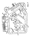
- FIG. 1 an optical system which directs a collimated light beam 21 onto an optic or magneto-optic storage disk 19 is shown.
- the optical system 10 is split into two assemblies, a stationary optical assembly which contains the bulkier, more massive and more electrically complex components and a moving optical assembly of minimum mass and maximum ruggedness which focuses a spot of light on the recording medium and moves this spot radially and axially as required.
- both assemblies may be combined in a single moving optical assembly.
- the stationary optical assembly 11 which provides the collimated light beam 21 is mounted on the storage system frame or base (not shown).
- the moving optical assembly or actuator 13 which carries an objective lens 25 and a mirror 23 focuses the light beam spot 27 on the recording disk 19.
- the actuator 13 moves transversely along rail 15 on rollers 17 moving the spot 27 across the disk 19 in a radial path.
- Fig. 1 shows an optical system including a linear actuator 13
- the optical system 10 may alternately employ a rotary actuator rather than the linear actuator 13.
- the recording disk 19 is typically fixed to a spindle which is driven by an external motor (not shown) to rotate the disk.
- the stationary optical assembly 11 typically includes the light source and the necessary detectors.
- the actuator assembly 13, objective lens 25, mirror 23 and appropriate electronic circuitry for controlling the electrical and mechanical components do not form part of the present invention and will not be further described here.
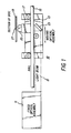
- the wedge prism assembly 9 comprises an optically transparent wedge 31, a 45 degree right isosceles triangular prism 33 bonded to the surface B of the transparent wedge 31, a rhomboidal prism 43 which is bonded to the exit surface 42 of prism 33, a smaller 45 degree right isosceles triangular prism 44 bonded to prism 43 at surface 46 and two planoconvex lenses 45 and 47 which are bonded to the exit surfaces of prism 43 and 44, respectively.
- the planoconvex lenses 45, 47 may or may not have optical coatings on their convex surfaces 48.
- Each of the optical components in the wedge prism assembly 9 is bonded or cemented to its adjacent optical component utilizing a transparent optical cement (a transparent refractive index matching cement such as that manufactured by the Norland Company is suitable for this purpose).
- a light source 37 such as a semiconductor laser, emits a divergent elliptical light beam which is gathered and converted to a parallel or collimated beam 22 in collimating lens 35.
- Light beam 22 is incident on surface A of wedge 31 where a portion 22 of the beam is reflected and lost to the system and a portion 21 of the beam is transmitted through surface A.
- An entrance window is defined at that portion of surface A where the light beam 22 is incident and transmitted through surface A into the wedge 31.
- Surface A provides anamorphic expansion of light beam 22 to form the circular collimated beam 21 which passes through prism 33 to the objective lens 25 and hence is focused onto the disk 19 (as shown in Fig. 1).
- Light beam 21 is reflected by disk 19 back to prism 33 which in combination with surface B of wedge 31 and multilayer thin film optical coatings form a polarizing beamsplitter where the reflected light beam 21 is split into a data beam 34 and a tracking/focusing or servo beam 32.
- the servo beam 32 passes through surface B of wedge 31 and is incident on the internal side of surface A of wedge 31 to be reflected out of exit window 36 and through servo lens 39 to servo detector 49.
- the exit window 36 is defined as that portion of surface B through which the servo beam 32 exits the wedge 31.
- the data beam 34 passes through the exit window formed by the top surface 42 of prism 33 into prisms 43 and 44.
- Prisms 43 and 44 together with multilayer thin film optical coatings at surface 46 form a second polarising beamsplitter splitting the data beam 34 into two complementary data beams 34a and 34b and guide the complementary beams through the planoconvex lenses 45 and 47 to the data detector assembly 51.
- wedge 31 is a six-sided, wedge-shaped optically transparent prism of optical grade glass (Grade A fine annealed BK-7 is suitable for this purpose) formed by two plane surfaces denoted A and B.
- Surface A provides anamorphic expansion of light beam 22 incident on surface A and a changing of the direction of beam 22 after transmission through wedge 31 and surface B.
- Control of the direction of beam 21 after transmission through surface B is achieved by attachment of an additional component such as prism 33 to surface B.
- a polarization beamsplitter is formed and partial reflection at surface B splits the reflected beam 21 into two components, the data beam 34 and the servo beam 32. Reflection of beam 32 at the interior surface of surface A separates the servo beam 32 from the incident beam 21. A portion of surface B also serves as an exit window for the servo beam 32 and is formed such that the servo beam 32 exits surface B at substantially Brewster's angle.
- the dihedral angle, indicated by reference numeral 53, formed by the extensions of surfaces A and B of wedge 31 controls (1) the anamorphic expansion ratio of surface A, (2) the reflectance R at surface A, (3) the angle of incidence of the servo beam 32 on the exit window portion 36 of surface B such that the servo beam 32 is transmitted through exit window 36 at substantially Brewster's angle and (4) the angle that the data beam 34 is reflected from surface B at the interface between the wedge 31 and prism 33.
- the dihedral angle 53 is optimized to provide a circular light beam 22 from the elliptical light beam 21 and to provide an angle of incidence at surface B for the servo beam 32 at substantially Brewster's angle. (At Brewster's angle reflection for P-polarized light vanishes and the need for an antireflective coating on surface B is eliminated.)
- Fig. 4b an analysis of the servo beam portion 32 of the return light beam 21 utilizing Snell's law provides an expression to calculate and optimize the dihedral angle ⁇ (53). To simplify the geometry, the angle of incidence of the return beam 21 with surface B is taken at 45 degrees.
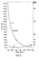
- Fig. 5 is a graph showing the relationship between the wedge dihedral angle ⁇ (reference numeral 53 as shown in Fig. 3b) for example at an angle of 6.08 degrees, and the reflectances R A , R B at surface A and B, respectively, as defined by equations (5) and (6) above.
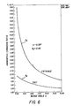
- Fig. 6 is a graph showing the relationship between the wedge dihedral angle ⁇ and the anamorphic expansion and compression factors A A , A B at surfaces A and B, respectively, as defined by equations (7) and (8).
- the wedge prism assembly 9 (as shown in Fig. 2) is comprised of a six-sided, wedge-shaped optically transparent prism 31 and a 45 degree right isosceles triangular prism 33 cemented to the lower portion of surface B.
- the prism 33 has an antireflective coated exit window 42 to prevent light losses and spurious reflections into the servo detector 49.
- the hypotenuse of prism 33 is coated to form a low-extinction polarizing beamsplitter.
- the low-extinction coating reflects appropriate quantities of the reflected light beam 21 in the S- and P- states of polarization to provide a data beam 34 to the data detector assembly 51.
- Both of the thin-film optical coatings utilized on the exit window and hypotenuse surfaces of prism 33 are selected to control the phase shift between the S- and P- states of polarization to eliminate the necessity of a compensating birefringent element (phase compensating element)in the optical head.
- the rhomboidal prism 43 and a second 45 degree right isosceles triangular prism 44 are cemented together at interface surface 46.
- Prism 44 and prism 43 adjacent the interface surface 46 together with a multilayer thin film coating form a high-extinction beamsplitter which splits the data beam 34 into two complementary beams 34a and 34b (as shown in Fig. 2) which are detected by the data detector assembly 51.
- the remaining portion of the prism 43 forms a trapezoidal prism which folds the reflected data beam 34b back to the plane of the transmitted data beam 34.
- Optical coatings at the fold mirror 40 are not required because of total internal light reflection at this surface.
- the beamsplitter assembly 43,44 is mounted on and cemented to the exit window (upper surface 42) of the prism 33 at 45 degrees to the orthogonal axes of the wedge assembly 31,33 to provide for proper separation of the two data signals 34a, 34b thus generated.
- the 45 degree rotated mounting of the beamsplitter 8,44 eliminates the necessity for a 1/2 wave compensator plate to rotate the plane of polarization of the data beam 34 thus reducing cost and complexity and improving performance margins.
- a pair of planoconvex lens 45,47 are mounted on the exit surfaces of the prism assembly 43,44 to focus and direct the complementary data beams 34a, 34b to the data detector assembly 51.
- the wedge prism assembly 9 is mounted on and cemented to an internal surface 57 of an enclosure or housing 50.
- the housing 50 is a conventional cast or molded metal or plastic part which maintains all of the optical and other components of the optical head in alignment and in the proper relationship to each other. Since the components of the wedge assembly are cemented or otherwise bonded together, the structural requirements on the housing 50 are substantially reduced relative to a design in which the housing also is required to maintain alignment of and positional relationships between the central optical components.
- the housing 50 also provides a mounting site for the collimating lens 35 and mounting brackets 41 for the servo lens 39.
- the collimating lens 35 is a commercially available component and converts the diverging elliptical light beam emitted by the light source 37 into a collimated beam.
- the light source 37 comprises a standard, commercially available diode laser and is mounted on an external surface 55 of the housing 50 opposite the collimating lens 35.
- An aperture is provided through the housing wall to allow the laser beam to pass through to the collimating lens 35.
- the aspect ratio of the laser's divergent far-field radiation pattern is matched to the expansion ratio of the anamorphic surface (surface A) of the wedge 31, so that the light beam 21 exiting the wedge 31 is nominally round or circular.
- the housing 50 has an aperture 28 formed in a wall or corner opposite the wedge assembly prism 33 face 26 to allow the transmitted and reflected light beam 21 to exit and enter the housing 50.
- the servo lens 39 is a commercially available component and is internally mounted in housing 50 in brackets 41 and focuses and directs the servo beam 32 to the servo detector 49.
- the servo detector 49 is mounted on an external surface 59 of the housing 50 opposite the servo lens 39.
- An aperture (not shown) is provided through the housing wall to allow the servo beam to be incident on the servo detector.
- the servo detector assembly 49 generates both tracking and focus error signals. Any of several well-known servo detection techniques may be used for this application.
- the data detector assembly 51 is mounted on an external surface 59 of the housing 50 opposite the pair of planoconvex lens 45 and 47.
- the data detector assembly 51 is conventional in nature and includes two detectors which generate a data signal derived from the changing polarization state of the data beams.
Landscapes
- Physics & Mathematics (AREA)
- Optics & Photonics (AREA)
- Optical Head (AREA)
- Optical Elements Other Than Lenses (AREA)
Applications Claiming Priority (2)
| Application Number | Priority Date | Filing Date | Title |
|---|---|---|---|
| US07/355,738 US5070493A (en) | 1989-05-22 | 1989-05-22 | Wedge prism assembly for optical information storage |
| US355738 | 1994-12-14 |
Publications (3)
| Publication Number | Publication Date |
|---|---|
| EP0399650A2 true EP0399650A2 (de) | 1990-11-28 |
| EP0399650A3 EP0399650A3 (de) | 1991-02-27 |
| EP0399650B1 EP0399650B1 (de) | 1995-03-01 |
Family
ID=23398643
Family Applications (1)
| Application Number | Title | Priority Date | Filing Date |
|---|---|---|---|
| EP90304136A Expired - Lifetime EP0399650B1 (de) | 1989-05-22 | 1990-04-18 | Keilförmige prismatische Anordnung zur optischen Informatonsspeicherung |
Country Status (6)
| Country | Link |
|---|---|
| US (1) | US5070493A (de) |
| EP (1) | EP0399650B1 (de) |
| JP (1) | JP3069117B2 (de) |
| KR (1) | KR100190739B1 (de) |
| CA (1) | CA2001038C (de) |
| DE (1) | DE69017261T2 (de) |
Cited By (2)
| Publication number | Priority date | Publication date | Assignee | Title |
|---|---|---|---|---|
| WO1993007616A1 (en) * | 1991-10-02 | 1993-04-15 | Honeywell Inc. | Optical head for magneto-optical system |
| EP1255134A1 (de) * | 2001-04-30 | 2002-11-06 | Samsung Electronics Co., Ltd. | Reflektierendes zusammengesetzes Prisma und optisches Aufnahmegerät mit diesem Prisma |
Families Citing this family (12)
| Publication number | Priority date | Publication date | Assignee | Title |
|---|---|---|---|---|
| US5223970A (en) * | 1989-03-16 | 1993-06-29 | Asahi Kogaku Kogyo Kabushiki Kaisha | Optical axis adjusting mechanism and method for optical information recording and reproducing device, and jig therefor |
| JPH03116567A (ja) * | 1989-09-29 | 1991-05-17 | Canon Inc | 光磁気情報再生装置 |
| US5835472A (en) * | 1990-07-31 | 1998-11-10 | Omron Corporation | Optical pickup device with substantially mutually orthogonal reflection surfaces |
| US5420848A (en) * | 1990-08-02 | 1995-05-30 | Canon Kabushiki Kaisha | Optical system for optical information recording/reproducing apparatus having a galvano mirror |
| JPH04364231A (ja) * | 1991-01-07 | 1992-12-16 | Toshiba Corp | 光学ヘッド装置 |
| JP3159746B2 (ja) * | 1991-01-11 | 2001-04-23 | 旭光学工業株式会社 | 光磁気ディスク装置の信号検出系 |
| JPH05210005A (ja) * | 1992-01-30 | 1993-08-20 | Canon Inc | ビーム・スプリッター |
| US5432763A (en) * | 1993-03-15 | 1995-07-11 | Hewlett-Packard Company | Subminiature rotary actuator optical head |
| JP3167066B2 (ja) * | 1993-10-06 | 2001-05-14 | キヤノン株式会社 | 光記録再生装置 |
| US5548443A (en) * | 1995-05-31 | 1996-08-20 | Texas Instruments Incorporated | Light separator for testing DMD performance |
| JP2001201615A (ja) * | 2000-01-21 | 2001-07-27 | Sony Corp | 光学素子および光ピックアップ |
| US8381685B2 (en) | 2009-05-29 | 2013-02-26 | Pioneer Pet Products, Llc | Pet fountain |
Citations (3)
| Publication number | Priority date | Publication date | Assignee | Title |
|---|---|---|---|---|
| EP0138026A2 (de) * | 1983-10-13 | 1985-04-24 | International Business Machines Corporation | Phase verzögerndes Element und Prisma für ein optisches Datenspeichersystem |
| JPS63166031A (ja) * | 1986-12-26 | 1988-07-09 | Brother Ind Ltd | 光ピツクアツプ |
| EP0323320A2 (de) * | 1987-12-25 | 1989-07-05 | Copal Company Limited | Optischer Kopf und Spurführungsmethode unter Benutzung desselben |
Family Cites Families (8)
| Publication number | Priority date | Publication date | Assignee | Title |
|---|---|---|---|---|
| DE3683833D1 (de) * | 1985-11-30 | 1992-03-19 | Toshiba Kawasaki Kk | Optischer kopf. |
| EP0225564A3 (en) * | 1985-11-30 | 1988-07-06 | Kabushiki Kaisha Toshiba | Optical head |
| JPS63121540A (ja) * | 1986-11-12 | 1988-05-25 | Hitachi Ltd | 電気鉄道用回生変電所システム |
| JP2547575B2 (ja) * | 1987-06-19 | 1996-10-23 | ハウス食品株式会社 | 固液混合物の供給装置 |
| US4959824A (en) * | 1987-07-31 | 1990-09-25 | Minolta Camera Kabushiki Kaisha | Optical information record/pickup head assembly |
| JPH02185726A (ja) * | 1989-01-10 | 1990-07-20 | Alps Electric Co Ltd | 光ピックアップにおける光学系の調整方法ならびに調整装置 |
| JP2956905B2 (ja) * | 1989-03-20 | 1999-10-04 | 富士通株式会社 | 光ディスク装置 |
| JPH02260143A (ja) * | 1989-03-30 | 1990-10-22 | Alps Electric Co Ltd | 光ピックアップ用光学装置 |
-
1989
- 1989-05-22 US US07/355,738 patent/US5070493A/en not_active Expired - Lifetime
- 1989-10-19 CA CA002001038A patent/CA2001038C/en not_active Expired - Fee Related
-
1990
- 1990-04-18 EP EP90304136A patent/EP0399650B1/de not_active Expired - Lifetime
- 1990-04-18 DE DE69017261T patent/DE69017261T2/de not_active Expired - Fee Related
- 1990-05-21 KR KR1019900007241A patent/KR100190739B1/ko not_active IP Right Cessation
- 1990-05-22 JP JP2132402A patent/JP3069117B2/ja not_active Expired - Fee Related
Patent Citations (3)
| Publication number | Priority date | Publication date | Assignee | Title |
|---|---|---|---|---|
| EP0138026A2 (de) * | 1983-10-13 | 1985-04-24 | International Business Machines Corporation | Phase verzögerndes Element und Prisma für ein optisches Datenspeichersystem |
| JPS63166031A (ja) * | 1986-12-26 | 1988-07-09 | Brother Ind Ltd | 光ピツクアツプ |
| EP0323320A2 (de) * | 1987-12-25 | 1989-07-05 | Copal Company Limited | Optischer Kopf und Spurführungsmethode unter Benutzung desselben |
Non-Patent Citations (3)
| Title |
|---|
| IBM TECHNICAL DISCLOSURE BULLETIN vol. 31, no. 9, February 1989, pages 161,162, Armonk, NY, US; "Compact Beam Bender" * |
| PATENT ABSTRACTS OF JAPAN vol. 12, no. 278 (P-738)(3125), 1 August 1988; & JP-A-6356823 (MATSUSHITA ELECTRIC) 11.03.1988 * |
| PATENT ABSTRACTS OF JAPAN vol. 12, no. 436 (P-787)(3283), 17 November 1988; & JP-A-63166031 (BROTHER IND. LTD.) 09.07.1988 * |
Cited By (3)
| Publication number | Priority date | Publication date | Assignee | Title |
|---|---|---|---|---|
| WO1993007616A1 (en) * | 1991-10-02 | 1993-04-15 | Honeywell Inc. | Optical head for magneto-optical system |
| EP1255134A1 (de) * | 2001-04-30 | 2002-11-06 | Samsung Electronics Co., Ltd. | Reflektierendes zusammengesetzes Prisma und optisches Aufnahmegerät mit diesem Prisma |
| US7088664B2 (en) | 2001-04-30 | 2006-08-08 | Samsung Electronics Co., Ltd. | Reflection type compound prism and optical pickup apparatus employing the same |
Also Published As
| Publication number | Publication date |
|---|---|
| EP0399650B1 (de) | 1995-03-01 |
| JP3069117B2 (ja) | 2000-07-24 |
| KR100190739B1 (ko) | 1999-06-01 |
| KR900018925A (ko) | 1990-12-22 |
| CA2001038A1 (en) | 1990-11-22 |
| US5070493A (en) | 1991-12-03 |
| JPH0316040A (ja) | 1991-01-24 |
| DE69017261D1 (de) | 1995-04-06 |
| DE69017261T2 (de) | 1995-06-22 |
| EP0399650A3 (de) | 1991-02-27 |
| CA2001038C (en) | 1995-04-11 |
Similar Documents
| Publication | Publication Date | Title |
|---|---|---|
| US5432763A (en) | Subminiature rotary actuator optical head | |
| US6781927B1 (en) | Data storage system having an optical processing flying head | |
| CA1159149A (en) | Optical device for recording and reading on a data carrier | |
| US6081499A (en) | Magneto-optical data storage system having an optical-processing flying head | |
| US4387452A (en) | Optical device for the recording and reading of data media and optical memory system incorporating such a device | |
| US4733065A (en) | Optical head device with diffraction grating for separating a light beam incident on an optical recording medium from a light beam reflected therefrom | |
| EP0399650B1 (de) | Keilförmige prismatische Anordnung zur optischen Informatonsspeicherung | |
| JP3167066B2 (ja) | 光記録再生装置 | |
| JPH06101156B2 (ja) | 磁気光学ヘッド | |
| EP0288230A2 (de) | Fokusdetektor | |
| EP0558184B1 (de) | Optischer Kopf mit einem Strahlenteiler | |
| EP0606389B1 (de) | Optischer kopf für magneto-optisches system | |
| US5119352A (en) | Magneto optic data storage read out apparatus and method | |
| US5444677A (en) | Optical read/write head low angle beamsplitter and coplanar detectors | |
| JPH0513339B2 (de) | ||
| US5379286A (en) | Optical information recording-reproducing apparatus having a prism | |
| US5101393A (en) | Optical position error detection using complementary steep angle reflections/transmissions | |
| US5400306A (en) | Differential detection assembly for data retrieval from a data storage disk | |
| JPH0721580A (ja) | 光ヘッド並びにこれを用いた光ディスク装置およびこれに用いる伝搬型プリズム | |
| JP2862254B2 (ja) | マルチ・ビーム光ヘッド用アクチュエータ | |
| JP2647151B2 (ja) | 光ヘッド装置 | |
| EP0559452A2 (de) | Optischer Schreib/Lesekopf und optische Vorrichtung für dessen Gebrauch | |
| JPH04181525A (ja) | 光情報記録再生装置 | |
| JPH08306064A (ja) | 光学的情報記録再生装置 | |
| JPH0746440B2 (ja) | 光記録/再生装置 |
Legal Events
| Date | Code | Title | Description |
|---|---|---|---|
| PUAI | Public reference made under article 153(3) epc to a published international application that has entered the european phase |
Free format text: ORIGINAL CODE: 0009012 |
|
| AK | Designated contracting states |
Kind code of ref document: A2 Designated state(s): DE FR GB IT |
|
| PUAL | Search report despatched |
Free format text: ORIGINAL CODE: 0009013 |
|
| AK | Designated contracting states |
Kind code of ref document: A3 Designated state(s): DE FR GB IT |
|
| 17P | Request for examination filed |
Effective date: 19910618 |
|
| 17Q | First examination report despatched |
Effective date: 19931011 |
|
| GRAA | (expected) grant |
Free format text: ORIGINAL CODE: 0009210 |
|
| AK | Designated contracting states |
Kind code of ref document: B1 Designated state(s): DE FR GB IT |
|
| ITF | It: translation for a ep patent filed |
Owner name: SOCIETA' ITALIANA BREVETTI S.P.A. |
|
| REF | Corresponds to: |
Ref document number: 69017261 Country of ref document: DE Date of ref document: 19950406 |
|
| ET | Fr: translation filed | ||
| PLBE | No opposition filed within time limit |
Free format text: ORIGINAL CODE: 0009261 |
|
| STAA | Information on the status of an ep patent application or granted ep patent |
Free format text: STATUS: NO OPPOSITION FILED WITHIN TIME LIMIT |
|
| 26N | No opposition filed | ||
| REG | Reference to a national code |
Ref country code: GB Ref legal event code: 732E |
|
| REG | Reference to a national code |
Ref country code: FR Ref legal event code: TP |
|
| REG | Reference to a national code |
Ref country code: GB Ref legal event code: IF02 |
|
| PGFP | Annual fee paid to national office [announced via postgrant information from national office to epo] |
Ref country code: GB Payment date: 20050413 Year of fee payment: 16 |
|
| PGFP | Annual fee paid to national office [announced via postgrant information from national office to epo] |
Ref country code: FR Payment date: 20050418 Year of fee payment: 16 |
|
| PGFP | Annual fee paid to national office [announced via postgrant information from national office to epo] |
Ref country code: DE Payment date: 20050531 Year of fee payment: 16 |
|
| PG25 | Lapsed in a contracting state [announced via postgrant information from national office to epo] |
Ref country code: GB Free format text: LAPSE BECAUSE OF NON-PAYMENT OF DUE FEES Effective date: 20060418 |
|
| PGFP | Annual fee paid to national office [announced via postgrant information from national office to epo] |
Ref country code: IT Payment date: 20060430 Year of fee payment: 17 |
|
| PG25 | Lapsed in a contracting state [announced via postgrant information from national office to epo] |
Ref country code: DE Free format text: LAPSE BECAUSE OF NON-PAYMENT OF DUE FEES Effective date: 20061101 |
|
| GBPC | Gb: european patent ceased through non-payment of renewal fee |
Effective date: 20060418 |
|
| REG | Reference to a national code |
Ref country code: FR Ref legal event code: ST Effective date: 20061230 |
|
| PG25 | Lapsed in a contracting state [announced via postgrant information from national office to epo] |
Ref country code: FR Free format text: LAPSE BECAUSE OF NON-PAYMENT OF DUE FEES Effective date: 20060502 |
|
| PG25 | Lapsed in a contracting state [announced via postgrant information from national office to epo] |
Ref country code: IT Free format text: LAPSE BECAUSE OF NON-PAYMENT OF DUE FEES Effective date: 20070418 |