EP0323320A2 - Optischer Kopf und Spurführungsmethode unter Benutzung desselben - Google Patents
Optischer Kopf und Spurführungsmethode unter Benutzung desselben Download PDFInfo
- Publication number
- EP0323320A2 EP0323320A2 EP88403276A EP88403276A EP0323320A2 EP 0323320 A2 EP0323320 A2 EP 0323320A2 EP 88403276 A EP88403276 A EP 88403276A EP 88403276 A EP88403276 A EP 88403276A EP 0323320 A2 EP0323320 A2 EP 0323320A2
- Authority
- EP
- European Patent Office
- Prior art keywords
- light beams
- diffracted light
- light beam
- optical disk
- optical
- Prior art date
- Legal status (The legal status is an assumption and is not a legal conclusion. Google has not performed a legal analysis and makes no representation as to the accuracy of the status listed.)
- Granted
Links
Images


Classifications
-
- G—PHYSICS
- G11—INFORMATION STORAGE
- G11B—INFORMATION STORAGE BASED ON RELATIVE MOVEMENT BETWEEN RECORD CARRIER AND TRANSDUCER
- G11B7/00—Recording or reproducing by optical means, e.g. recording using a thermal beam of optical radiation by modifying optical properties or the physical structure, reproducing using an optical beam at lower power by sensing optical properties; Record carriers therefor
- G11B7/12—Heads, e.g. forming of the optical beam spot or modulation of the optical beam
- G11B7/135—Means for guiding the beam from the source to the record carrier or from the record carrier to the detector
- G11B7/1353—Diffractive elements, e.g. holograms or gratings
-
- G—PHYSICS
- G11—INFORMATION STORAGE
- G11B—INFORMATION STORAGE BASED ON RELATIVE MOVEMENT BETWEEN RECORD CARRIER AND TRANSDUCER
- G11B7/00—Recording or reproducing by optical means, e.g. recording using a thermal beam of optical radiation by modifying optical properties or the physical structure, reproducing using an optical beam at lower power by sensing optical properties; Record carriers therefor
- G11B7/08—Disposition or mounting of heads or light sources relatively to record carriers
- G11B7/09—Disposition or mounting of heads or light sources relatively to record carriers with provision for moving the light beam or focus plane for the purpose of maintaining alignment of the light beam relative to the record carrier during transducing operation, e.g. to compensate for surface irregularities of the latter or for track following
Definitions
- the present invention relates to an optical head used for writable-type optical disks, and to a tracking method which employs the optical head. More particularly, the invention relates to improvements in a conventional so-called tri-beam method.
- Optical disks from which data can be read owing to a change in reflection factor and on which data can be written are referred to as WORM (WRITE-ONCE READ-ONLY MEMORY)- or DRAW-type optical disks.
- a recording material such as Te (tellurium) is vaporized by irradiation with a laser beam, thereby to form pits in the surface of the disk.
- Data is read from the disk on the basis of the difference between the reflection factors (the reflection intensities) of the pitted parts and unpitted parts of the disk surface.
- a phase change-type optical disk has recently been developed as an erasable optical disk.
- the phase state of a recording material is changed by the difference between the power levels of an irradiating laser beam.
- changes in the reflection factors of the unchanged and changed parts of the recording material are read as data. Since the changes in the phase state are reversible, the optical disk of the phase change-type possesses an erasability property.
- the triple-beam method (1) is chiefly adopted for the tracking of a playback-only optical disk as stated in, for example, Japanese Patent Publication (KOKOKU) No. 58-56164.
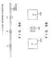
- the principle of the tri-beam method is illustrated in Fig. 9A.
- secondary light (corresponding to light of orders ⁇ 1 in Fig. 9A) is produced from a laser beam by the use of, for example, a diffraction grating, the reflected light of the secondary light from the surface of the optical disk is received by photodetectors 200, 202 shown in Fig. 9B, an a tracking servo signal is generated on the basis of the difference between the output signals of the detectors and is utilized for tracking.
- the servo tracking is performed so as to equalize the received quantities of light of order -1 and order +1.
- the push-pull method (hereinafter referred to as the "PP method") (2) performs servo tracking in such a manner that, as stated in U.S.P. 3,913,076 (Japanese Patent Publication No. 55-26529), etc., a tracking servo signal is formed from an interference wave between reflected light from a pre-groove formed in the surface of the optical disk beforehand and reflected light from outside the pre-groove, whereupon an objective for focusing a laser beam on the disk is shifted in accordance with the signal.
- This PP method is chiefly adopted for the servo tracking of the writable optical disk.
- the above deviation can be cancelled by applying a gain ratio (an offset value ⁇ ) between the outputs (signals E and F) of the detectors 200 and 202 and then setting the tracking signal to E - ⁇ F
- the method of applying the offset cannot produce stable tracking signals unless the deviations are compensated for by changing the offset values as, for example, ⁇ 1, ⁇ 2, ... for the respective different materials of the optical disks. In actual practice, however, it is impossible to change the offset value for every material in this manner. That is, the application of the tri-beam method to the writing operation of the optical disk involves a first problem in which compensation cannot be made for fluctuations in the reflection factors corresponding to the materials of the optical disks.
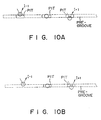
- the tri-beam method is applied to playback of the optical disk already written on, the reflection intensities of the light of the orders +1 and -1 from areas before and behind a data reading pit are equal (I ⁇ 1 ⁇ I+1) in the course of reading the pit, as illustrated in Fig. 10A. It is therefore unnecessary to provide the photodetection signals with the offset as in the writing operation.
- the tri-beam method is disadvantageous in that it is necessary to contrive circuitry which distinguishes between the writing mode and the reading mode and then applies the aforementioned offset only in the former. This is the second problem encountered in the tri-beam method.
- the PP method since the PP method utilizes the interference between the reflected light from the pre-groove and from outside this pre-groove as stated before, it does not cause the offset ascribable to the difference in the reflected light intensities in the writing operation as in the case of the triple-beam method.
- the objective since the objective is displaced for tracking as explained above, the reflected light beams from the disk shift transversely and it is eventually required to provide the servo signal with an offset magnitude.
- the control of this offset is complicated and is unsuited to inexpensive playback-only optical disks such as CD's.
- the PP method is mainly adopted for optical disks requiring high precision.
- both the tri-beam method and the PP method which are the typical tracking methods, involve some disadvantages.
- the former is unsuitable especially for the writable (WORM type) optical disk, while the latter is suitable for the writable optical disk but leaves the problem of the lens shift unsolved.
- the present has been devised in order to eliminate the disadvantages of the prior art, and its object is to provide a tracking method based on a novel tri-beam method capable of stable tracking in both the modes of writing data onto an optical disk and reading data from the optical disk and independently of the optical disk material, as well as an optical head to which the tracking method is applied.
- an optical head having light beam generating means for generating a light beam, and being usable for WORM type and phase change-type optical disk devices, comprising diffraction means located on an optical path of the light beam for diffracting the light beam into a plurality of diffracted light beams, the plurality of diffracted light beams being generated in a number of at least three so as to establish a positional relationship in which they do not lie on a single line in a cross-sectional distribution thereof (here a reflected light beam from an optical disk, which reflected light beam is one of the three diffracted light beams that lies at a foremost or rearmost position in a forward rotating direction of the optical disk, is employed for reading or writing data), and two first light-receiving means disposed on an optical path of reflected light of the remaining two diffracted light beams from the optical disk, and arranged at different positions so as to receive the reflected light beams in order to produce a tracking serv
- a tracking method for an optical head usable for WORM-type and phase change-type optical devices comprises the steps of: producing three diffracted light beams from a single light beam so as not to lie on a single straight line in a cross-sectional distribution thereof; employing as a beam, for reading or writing data, a reflected light beam from an optical disk, of one of the three diffracted light beams which lies at a foremost or rearmost position in a forward rotating direction of the optical disk; and employing reflected light beams of the remaining two diffracted light beams from the optical disk as beams for tracking.
- the plurality of diffracted light beams fall into a positional relationship in which they do not lie on a single straight line in the cross-sectional distribution thereof, so that two of them can be employed for tracking.
- the data reading or writing diffracted light beam is projected on the foremost (or rearmost) position in the forward rotating direction of the optical disk, namely on a position lying ahead of (or to the rear of) the two diffracted light beams for producing the tracking signal.
- the two diffracted light beams for producing the tracking signal are projected on areas in which data items has already been written (or areas in which data has not yet been written), in both a writing mode and a reading mode, so that both the reflected light beams of the two diffracted light beams are obtained under the same condition.
- stable and precise tracking signals can be obtained in both the writing mode and reading mode.
- the diffraction means comprises diffraction grating located perpendicular to an optical axis of the light beam from the light beam generating means, and a prism so disposed that the diffracted light beams from the diffraction grating enter it obliquely.
- the refracted light beams of the at least three diffracted light beams from the prism are projected perpendicularly to a surface of the optical disk.
- Beam shaping can be realized simultaneously with the function of obtaining the plurality of diffracted light beams in the positional relationship in which they do not lie on the single straight line in the cross-sectional distribution thereof, so that the optical head can be reduced in size and lowered in cost.
- the diffracted light beam lying at the foremost or rearmost position is a light beam of order 0, and the remaining two diffracted light beams are light beams of orders 1 and 2.
- the light spectrum of the order 0 has the largest quantity of light.
- the optical head further comprises second light-receiving means for receiving the reflected light beam from a surface of the disk, the reflected light being the diffracted light beam which lies at the foremost or rearmost position, a signal from the second light-receiving means being used for playing back the read data or for a focusing servo control operation.
- the diffracted light beam (of the order 0 lying at the foremost or rearmost position lies at the foremost position)
- the remaining light beams are projected on written areas of a surface of the optical disk in the writing mode and playback mode.
- the remaining diffracted light beams are projected on areas to-be-erased in an erasing mode.
- the remaining two diffracted light beams are reflected under the same condition, so that the ratio between the light quantities of the two reflected light beams does not fluctuate in the writing, erasing and reading mode.
- the remaining diffracted light beams are projected on unwritten areas of a surface of the optical disk in a writing mode. Moreover, they are projected on written areas in the playback mode and erasing mode. Thus, the remaining two diffracted light beams are reflected under the same condition, so that the light quantities of the two reflected light beams and the ratio between these light quantities do not fluctuate in the writing, erasing and reading modes.
- a further aspect of the present invention is characterized in that the diffraction means comprises a first diffraction grating, and a second diffraction grating which has a grating pattern extending in a direction different from that of a grating pattern of the first diffraction grating. Planes of the first and second diffraction gratings intersect at right angles to the incident light beam.
- a still furhter aspect of the present invention is characterized in that the diffracted light beam lying at the foremost or rearmost position is projected on a pre-groove provided on the optical disk, and the remaining two diffracted light beams are projected on positions which are substantially equidistant from the pre-groove in a direction normal to the pre-groove.
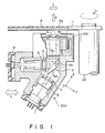
- Fig. 1 is a partially sectional side view showing the essential portions of an optical disk device to which an actuator for an optical head according to one embodiment of the invention is applied.
- an optical disk 9 is formed of a disk provided with a pre-groove 9g in the shape of concentric circles.
- the optical disk 9 rotates in such a manner that a predetermined turning force in the direction of arrow D is transmitted thereto from a rotary shaft 20 driven by rotation means (not shown), while it is detachably attached to the rotary shaft 20 by attaching means, not shown.
- An optical head assembly 200 is fixed to parallel direction drive means, not shown, and is accessible to any desired track of the pre-groove 9g of the aforementioned optical disk 9 through movement in the direction of arrow L, which is the radial direction of the optical disk 9.
- numeral 1 denotes a semiconductor laser which emits a laser beam
- numeral 4 denotes an objective lens which serves to condense the light beam on the pre-groove 9g.
- An optical block 8 comprises a beam shaping prism 8a, a polarizing beam splitter (hereinafter abbreviated to "PBS") 8b which passes the incident light from the laser 1 and reflects reflected light from the optical disk 9.
- PBS polarizing beam splitter
- Shown at numeral 2 is a detector comprising, for example, photodiodes for receiving the reflected light from the PBS 8b. It is well known that a focusing signal and a tracking signal are obtained from the received light signals.
- the assembly 200 includes a collimating lens 3 by which the laser beam emitted from the semiconductor laser 1 is converted into a collimated beam and which is disposed at a predetermined distance from the semiconductor laser 1, and a diffraction grating 7 disposed on the exit side of the collimating lens 3 for the collimated beam.
- the objective lens 4 is mounted on the upper surface 11 of the actuator 100 through a lens holder 4a.
- the collimated light beam reflected from the PBS 8b passes through a condenser 5 as well as a cylindrical lens 6 and is condensed on the detecting surface of the detector 2.
- This block 8 has the following constituents arrayed successively from its side nearest the laser 1:
- the optical head 200 thus constructed is required to condense the oscillated light, which is emitted by the semiconductor laser 1, on the pre-groove 9g of the optical disk 9 through the objective lens 4 at all times.
- the actuator 100 referred to above is servo-driven in a focusing direction indicated by arrow F in the figure and in a tracking direction indicated by arrow T.
- Fig. 2 is a plan view of the actuator 100 for the optical head stated above
- Fig. 3 is an exploded view of the optical head actuator 100.
- the optical head actuator 11 includes a movable member 100a and a yoke member 100b and is assembled and constructed so that the movable member 100a may be loosely fitted around the supporting shaft 112 of the yoke member 100b slidably and turnably.
- the upper surface of the optical head actuator 100 is substantially elliptical, and an outer peripheral wall 111b depends from the outer edge of the upper surface 111.
- the contour of the upper surface 111b is substantially in the shape of an ellipse having a minor axis of 2 x R1 and a major axis of l1 + l2 + R2 + R3, but is is accurately formed of two circular arcs of radius R1, one circular arc of radius R2, one circular arc of radius R3 and segmental parts connecting these circular arcs.
- a focusing coil 125 is wound round the outer peripheral wall 111b without any clearance therebetween.
- two pairs of tracking coils 126 are provided by bonding them to the outer surface of the focusing coil 125. The positions of bonding are determined so that the individual tracking coils 126 may be centered near the ends of the magnetic flux ranges K of the yoke member 100b.
- a bearing member 111a is formed so as to depend from the central part of the upper surface 111 to the same side as that of the outer peripheral wall 111b.
- the objective lens 4 is disposed at one end of the major axis side of the upper surface 111, a weight balance for the supporting shaft 112 to be described below is held in such a manner that a weight corresponding to the objective lens 4 is provided on the other end of the major axis side.
- the weight balance is maintained by increasing the thickness of the upper surface 111.
- the supporting shaft 112 is provided centrally of the yoke member 100b so as to support the aforementioned bearing member 111a in a loosely fit manner.
- Yoke pieces 114 are erected at both end parts of the yoke member 100b and establish magnetic field in the ranges indicated by K in Figs. 2 and 3, in cooperation with magnets 113 which are disposed at positions confronting the yoke pieces 114.
- a focusing coil-driver circuit 150 is connected to the focusing coil 125, while a tracking coil-driver circuit 160 is connected to the tracking coils 126.
- Each of the driver circuits is controlled by a servo circuit, not shown.
- the optical head actuator 100 When a predetermined current is caused to flow through the focusing coil 125 of the movable member 100a by the focusing coil-driver circuit 150, the movable member 100a slides in the axial direction of the supporting shaft 112 of the yoke member 100b in accordance with Fleming's law. Further, when predetermined currents are caused to flow through the tracking coils 126 by the tracking coil-driver circuit 160, the movable member 100a turns about the supporting shaft 112 of the yoke member 100b in accordance with Fleming's law.
- the closed magnetic fields within the ranges illustrated at K act upon the tracking coils 126 which lie within ranges indicated by the radii R1 in Fig. 2, so that sufficient torques are attained for both turning and sliding.
- the construction of the actuator 100 has been chiefly described from the viewpoint of obtaining a sufficient torque when moving the actuator in the focusing direction and a sufficient torque when moving the actuator in the tracking direction.
- the tracking method employing the optical head will be described next. Although this will become obvious from the ensuing description, it is clearly stated here that the tracking method of the embodiment is not realized only when the actuator shown in Figs. 2 and 3 is adopted, but that it can also be applied to any actuator of conventional construction merely by fulfilling certain conditions.
- FIG. 5 A part (a) in Fig. 5 is a diagram of the optical path viewed in the direction of the Y axis, a part (b) is a diagram of the optical path viewed in the direction of the Z axis, and a part (c) is a diagram of the spots of light beams on an optical disk as viewed in a normal direction to the surface of the optical disk.
- the laser beam emitted from the semiconductor laser 1 is the P polarized light parallel to the plane of Fig. 1, and is converted into the collimated beam by the collimating lens 3.
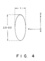
- the cross-sectional emission distribution of the collimated beam on this occasion is in the shape of an ellipse whose major axis extends in a direction perpendicular to the direction of polarization (in the Z direction in Fig. 1) and in which the ratio between the major axis and the minor axis is about 2.5:1 - 3:1.
- This shape is due in large part to the shape of the light emission face of the semiconductor laser 1.
- the elliptical shape is corrected into a circle by the prism 8a.
- the diffraction grating 7 When the collimated beam is incident upon the diffraction grating 7, the latter generates secondary light (light of orders ⁇ 1, ⁇ 2 and ⁇ 3 in the example of Fig. 5) in the direction of the Z axis, as illustrated in Fig. 5.
- the illustration of PBS 8b is omitted in order to avoid complicating the drawing. Since the incident beams entering the PBS 8b are the P polarized light, they pass through the PBS 8b without any change and are corrected into circularly polarized light by the quarter-wave plate 8c. The beams of the circularly polarized light are focused on the surface of the optical disk 9 by the objective lens 4, and are reflected therefrom.
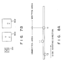
- the reflected light from the disk 9 is converted into a collimated beam by the objective lens 4. Thereafter, the beam is polarized into the S polarized light this time by the quarter-wave plate 8c, and the polarized light enters the PBS 8b again. Since the S polarized light is reflected by the PBS 8b, it is condensed on the six-sector detector 2 by the condenser 5 as well as the cylindrical lens 6. The shape of the light-receiving face of the detector 2 is a shown in Fig. 7B.
- the six-sector detector 2 is such that a four-sector detector 301 for producing signals for focusing and for reading data and two detectors 300 and 302 for tracking are arrayed as shown in Fig. 7B, and it is basically different in arrangement from the prior-art detector shown in Fig. 9B. The reason for the difference will be described below.
- the control (focusing servo control) in which the objective lens 4 is controlled so as to condense the beam on the optical disk is based on what is referred to as the "astigmatism method". More specifically, aberration is provided by the condenser 5 and the cylindrical lens 6, and the combined output: (A + D) - (B + C) of the light-receiving elements 301 of the six-sector detector 2 is used as a focusing error signal. This principle is well known and does not require explanation.
- This tracking method should be referred to as an "improved tri-beam method", in which the light beam of order 0 and the light beam of orders +1 and +2 (or orders -1 and -2) are generated by optical elements skillfully arranged on the optical path, so as to utilize the light beam of order 0 for data reading and for focusing servo control and the light beams of orders +1 and +2 (or the orders of -1 and -2) for tracking.
- Fig. 5(a) illustrates a situation in which the single collimated laser beam is diffracted into the plurality of diffracted light beams by the diffraction grating 17, with the Y axis taken in a direction perpendicular to the plane of the drawing.
- the light beam of order 0 and the secondary light beams enter the shaping prism 8a.
- This prisms 8a has two important functions. The first is to shape the substantially elliptical laser beam (refer to Fig. 4) so as to become substantially circular, and the second is to distribute the secondary light beams in the shape of a circular arc, as shown in Fig. 6, on a plane normal to the optical axis of the light beam of order 0.
- the shape of the spot on the beam from the laser diode 1 is elliptical and does not change even when the beam is diffracted by the diffraction grating 7. Accordingly, the shape of the spot of each of the secondary light beams from the diffraction grating 7 is substantially elliptical, as shown in Fig. 4, and the elliptical shape is made circular by the prism 8a.
- the spots of the respective secondary light beams are shaped into circles, but they are distributed on an imaginary circular arc 50 as shown in Fig. 6. That is, when the prism 8a for the first function, namely the circularizing function, is situated at the stage succeeding the diffraction grating 7, it simultaneously performs the second function.
- the first function is performed to effectively utilize the light beam of the semiconductor laser of low power and has long been performed in the art.
- the shaping prism is located ahead of the diffraction grating, and there is no optical head available in which the diffraction grating 7 is located at the stage preceding the shaping prism 8a as in this embodiment.
- the reason is that, in the prior art, the single beam of elliptical cross-section is first shaped into the single beam of circular cross-section, whereupon the aligned light beams of orders 0, +1 and -1, as shown in Fig. 9A, are obtained from the single circular beam. Therefore, it has not been possible to situate the shaping prism behind the diffraction grating.
- the light beam of order 0 is magnified times in the direction of the Y axis (in the direction of the minor axis in Fig. 4).
- the cross-sectional shape of the laser beam is the ellipse in which the ratio between the major axis and the minor axis is about 2.5:1 - 3:1, as shown in Fig. 4.
- the angle of incidence ⁇ of the light beam of order 0 on the prism 8a becomes 72°.
- the beam refracted by the shaping prism 8a is shaped to have an axial ratio of about 1:1 in cross section. Owing to the shaping, the output from the semiconductor laser 1 is utilized for reading/writing data and for tracking without being wasted.
- the secondary light beams from the shaping prism 8a are respectively shaped to be circular, but their distribution is curved, as illustrated in Fig. 6.
- the refractive index of the glass (BK7) of the prism 8a is 1.51
- the angle of incidence ⁇ of the zero-order light beam on the shaping prism 8a is 72°
- the angle of separation between the light beams of the orders 0 and 1 is 0.5°
- the angle of separation between the light beams of the orders 0 and 2 is 1°
- the focal distance of the objective lens 4 is 4 mm.
- the shifts of the first-order and second order light beams relative to the zero- order light beam in the tracking direction become about 0.1 um and 0.5 um, respectively.
- the pre-groove of the disk and the plurality of beams spots are brought into a positional relationship in which the light beam of order 0 is centered on the pre-groove and in which this pre-groove is held between the light beams of the orders +1 and +2.
- Such a positional relationship is established by rotating the entire optical head about the optical axis of the objective lens thereby to correct the positional relationship between the optical head and the disk surface.
- numeral 60 indicates the pre-groove after the correction of the positional relationship stated above, and numeral 61 the pre-groove before correction.
- Such a correction can also be made by changing the orientation of the diffraction grating 7 and the orientation of pre-groove in Fig. 1 so as to establish the positional relationship of the beams and the pre-grooves as illustrated in Fig. 7A.
- the zero-order light beam is projected on the pre-groove, and the +1-, +2-order light beams are projected on positions which are equally distant from the pre-groove.
- the reflected light of the light beams of the orders 0, +1, +2 is received by the six-sector detector 2, as shown in Fig. 7B.
- E and F denote signals from the respective light-receiving elements 300 and 302, tracking servo control may be performed so as to null the error signal E - ⁇ 12F where ⁇ 12 indicates the ratio between the light quantities of the first- and second-order light beams.
- E and F denote signals from the respective light-receiving elements 300 and 302
- the coefficient ⁇ is not "1"
- the coefficient is not changed by the tracking operation because it is the ratio between the light quantities of the first-order and second-order light beams. Therefore, the coefficient does not form the variable factor of an offset.
- the light-receiving elements 300 - 302 may be exactly the same as those of the prior art.
- Fig. 7A illustrates an aspect in which a writing diffracted beam lies at the rearmost position in the rotating direction of the optical disk.
- the rotating direction of the optical disk is rightward as view in the drawing, and the zero-order light beam generated by the optical head of the embodiment in Fig. 1 is employed as the writing beam, while the diffracted light beams of orders +1 and +2 are employed for tracking. Both the light beams of orders +1 and +2 are projected on the written areas of the optical disk in a writing mode and a playback mode.
- the diffracted light beam of order -1 is projected on the unwritten area and the diffracted light of order +1 is projected on the written area, so that the offset magnitude must be altered for every material in order to compensate for the difference in material.
- the two tracking beams are similarly projected on the written areas, and the reflection intensities thereof fluctuate similarly in spite of a change in the disk material, so that the change in the reflection intensity attributed to the difference is material is cancelled.
- the optical head and the tracking method according to the embodiment overcome the disadvantage of the prior art.
- the difference between the light quantities of the diffracted beams of orders 1 and 2 is compensated for by the gain ratio ⁇ 12. Since both the first-order and second-order light beams and second-order light beams are projected on similar areas, the difference between the light quantities of the diffracted beams does not give rise to an offset in the writing mode and reading mode. Therefore, once the gain ratio has been set at a prescribed value, stable tracking is realized in both the writing and reading modes. In the prior art, as explained in relation to Figs.
- the I ⁇ 1/I+1 ratio in the writing mode differs from that in the playback mode, so that the writing mode is required to be distinguished from the playback mode so as to form a different tracking signal (E - ⁇ F in contrast to E - F). Also in this respect, the tracking method of the embodiment overcomes the disadvantage of the prior art.
- the tracking method according to the above embodiment is realized by altering the arrangement of the optical elements in the optical head; hence, the specifications of the conventional optical disk media need not be subjected to any correction.
- the embodiment is advantageous in point of cost.
- the optical head can be reduced in size and is less susceptible to the adverse influence of environmental changes, such as changes in temperature and vibration, owing to the simplification of the optical system.
- the foregoing embodiment is arranged so that the writing or reading diffracted beam is the diffracted light beam at the rearmost position in the rotating direction of the optical disk, while the two tracking secondary light beams at foremost positions in the same direction are projected on the written areas.
- two tracking beams are collectively projected on unwritten areas, while a diffracted light beam at the foremost position in the rotating direction of the optical disk is employed as the writing or reading diffracted beam.
- the diffracted light beams of orders -1 and -2 projected on the unwritten areas are utilized for tracking.
- both beams are projected on the areas of the same reflecting condition, so that all the aforementioned features and effects of the foregoing embodiment are also achieved by the modification.
- the intensities of the reflected beams of the two secondary light beams in the writing mode become different from those in the reading mode, but the ratio between the light quantities of the two reflected beams is pertinent to the signal of servo tracking control.
- the light quantity ratio does not change even with the arrangement of Fig. 8A, no problem arises.
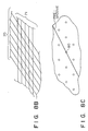
- the beam shaping prism 8a is utilized so as to attain the curved secondary light distribution as shown in Fig. 7A. Even with a different method, however, it is possible to generate secondary light beams the cross-sectional distribution of which is curved. That is, the secondary light beams in the distribution as shown in Fig. 7A can also be obtained by combining several diffraction gratings and prisms.
- the diffraction gratings can be replaced with a "wedge"-shaped prism which performs multiple reflection.
- a secondary light distribution as shown in Fig. 8C can be attained without the shaping prism 8a by combining two diffraction gratings 70 and 71 of different grating patterns as illustrated in Fig. 8B. More specifically, secondary light diverging laterally is generated by the diffraction grating 71 the grating pattern of which is set parallel to the plane of Fig. 8B. Then, when the zero-order light and secondary light from the diffraction grating 71 is caused to enter the diffraction grating 70 located at an inclination with respect to the diffraction grating 71, the large number of secondary light beams shown in Fig. 8C are obtained. Assuming that a light beam 80 is the zero-order light in Fig. 8C, light beams between which the pre-groove is held as shown in Fig. 7A are selected from among the other secondary light beams.
- a light beam of order 0 and at least two secondary light beams are produced from a single laser beam by an optical system, the zero-order light beam is used as a main beam for reading or writing data, and from among the secondary light beams, two light beams in a positional relationship in which they are not aligned with the zero-order light beam in the cross-sectional distribution thereof are selected so as to be used as beams for detecting a tracking signal.
- This measure eliminates the necessity to provide servo signals with unequal magnitudes in a writing mode and playback mode as in the prior-art tri-beam method.
- the offset magnitudes are also unstable.
- the zero-order light beam and the first-order and second-order light beams are respectively employed as the beam for data and the beams for tracking in the above embodiment, this is not always restrictive. The reason is that beams of desired powers can be generated by controlling numerical apertures, as stated earlier.
- the ratio between the light quantities of the first-order and second-order beams can also be set at "1" by changing the numerical aperture of the diffraction grating or changing the sectional shape of the grating.
Applications Claiming Priority (2)
| Application Number | Priority Date | Filing Date | Title |
|---|---|---|---|
| JP327444/87 | 1987-12-25 | ||
| JP62327444A JPH01171129A (ja) | 1987-12-25 | 1987-12-25 | 光学ヘッド及びトラッキング方法 |
Publications (3)
| Publication Number | Publication Date |
|---|---|
| EP0323320A2 true EP0323320A2 (de) | 1989-07-05 |
| EP0323320A3 EP0323320A3 (en) | 1990-05-30 |
| EP0323320B1 EP0323320B1 (de) | 1994-03-02 |
Family
ID=18199237
Family Applications (1)
| Application Number | Title | Priority Date | Filing Date |
|---|---|---|---|
| EP88403276A Expired - Lifetime EP0323320B1 (de) | 1987-12-25 | 1988-12-21 | Optischer Kopf und Spurführungsmethode unter Benutzung desselben |
Country Status (4)
| Country | Link |
|---|---|
| US (1) | US5062096A (de) |
| EP (1) | EP0323320B1 (de) |
| JP (1) | JPH01171129A (de) |
| DE (1) | DE3888157T2 (de) |
Cited By (3)
| Publication number | Priority date | Publication date | Assignee | Title |
|---|---|---|---|---|
| EP0399650A2 (de) * | 1989-05-22 | 1990-11-28 | Hewlett-Packard Company | Keilförmige prismatische Anordnung zur optischen Informatonsspeicherung |
| EP0865036A2 (de) * | 1997-03-12 | 1998-09-16 | Ricoh Company, Ltd | Optisches Abtastgerät |
| EP1093119A2 (de) * | 1999-10-12 | 2001-04-18 | Pioneer Corporation | Informationsaufzeichnungsgerät und Informationswiedergabegerät |
Families Citing this family (4)
| Publication number | Priority date | Publication date | Assignee | Title |
|---|---|---|---|---|
| US5694385A (en) * | 1993-09-24 | 1997-12-02 | Ricoh Comany, Ltd. | Optical pickup apparatus |
| KR0167462B1 (ko) * | 1995-10-31 | 1999-04-15 | 이형도 | 레이저 스캔닝 유니트의 콜리메이트 렌즈 조립구조 |
| JPH10199005A (ja) * | 1996-12-26 | 1998-07-31 | Sony Corp | 光学ピックアップ装置 |
| KR100452293B1 (ko) * | 2002-01-07 | 2004-10-08 | 삼성전기주식회사 | 광 픽업장치 |
Citations (3)
| Publication number | Priority date | Publication date | Assignee | Title |
|---|---|---|---|---|
| US3913076A (en) * | 1973-03-02 | 1975-10-14 | Thomson Brandt | Reading out and tracking a recorded diffractive trace with an elongated read out spot |
| FR2533732A1 (fr) * | 1982-09-28 | 1984-03-30 | Sony Corp | Appareil de reproduction optique |
| EP0241942A2 (de) * | 1986-04-18 | 1987-10-21 | Mitsubishi Denki Kabushiki Kaisha | Optischer Kopf |
Family Cites Families (4)
| Publication number | Priority date | Publication date | Assignee | Title |
|---|---|---|---|---|
| JPH0675297B2 (ja) * | 1981-08-28 | 1994-09-21 | 株式会社日立製作所 | 光学的情報記録再生装置 |
| JPS58147823A (ja) * | 1982-02-25 | 1983-09-02 | Mitsubishi Electric Corp | トラツクずれ検出装置 |
| US4720825A (en) * | 1984-02-06 | 1988-01-19 | Asahi Kogaku Kogyo Kabushiki Kaisha | Optical data reproducing devices having improved trick play capability |
| KR900008380B1 (ko) * | 1986-07-01 | 1990-11-17 | 미쓰비시덴기 가부시기 가이샤 | 광학식 헤드장치 |
-
1987
- 1987-12-25 JP JP62327444A patent/JPH01171129A/ja active Pending
-
1988
- 1988-12-20 US US07/287,291 patent/US5062096A/en not_active Expired - Fee Related
- 1988-12-21 DE DE3888157T patent/DE3888157T2/de not_active Expired - Fee Related
- 1988-12-21 EP EP88403276A patent/EP0323320B1/de not_active Expired - Lifetime
Patent Citations (3)
| Publication number | Priority date | Publication date | Assignee | Title |
|---|---|---|---|---|
| US3913076A (en) * | 1973-03-02 | 1975-10-14 | Thomson Brandt | Reading out and tracking a recorded diffractive trace with an elongated read out spot |
| FR2533732A1 (fr) * | 1982-09-28 | 1984-03-30 | Sony Corp | Appareil de reproduction optique |
| EP0241942A2 (de) * | 1986-04-18 | 1987-10-21 | Mitsubishi Denki Kabushiki Kaisha | Optischer Kopf |
Non-Patent Citations (4)
| Title |
|---|
| PATENT ABSTRACTS OF JAPAN * |
| PATENT ABSTRACTS OF JAPAN, vol. 11, no. 45 (P-546)(2492), 10 February 1987 * |
| PATENT ABSTRACTS OF JAPAN, vol. 7, no. 286 (P-244)(1431), 21 December 1983 * |
| PATENT ABSTRACTS OF JAPAN, vol. 8, no. 72 (P-265)(1509), 4 April 1984 * |
Cited By (7)
| Publication number | Priority date | Publication date | Assignee | Title |
|---|---|---|---|---|
| EP0399650A2 (de) * | 1989-05-22 | 1990-11-28 | Hewlett-Packard Company | Keilförmige prismatische Anordnung zur optischen Informatonsspeicherung |
| EP0399650A3 (de) * | 1989-05-22 | 1991-02-27 | Hewlett-Packard Company | Keilförmige prismatische Anordnung zur optischen Informatonsspeicherung |
| EP0865036A2 (de) * | 1997-03-12 | 1998-09-16 | Ricoh Company, Ltd | Optisches Abtastgerät |
| EP0865036A3 (de) * | 1997-03-12 | 1999-08-18 | Ricoh Company, Ltd | Optisches Abtastgerät |
| EP1093119A2 (de) * | 1999-10-12 | 2001-04-18 | Pioneer Corporation | Informationsaufzeichnungsgerät und Informationswiedergabegerät |
| EP1093119A3 (de) * | 1999-10-12 | 2003-12-10 | Pioneer Corporation | Informationsaufzeichnungsgerät und Informationswiedergabegerät |
| US6894955B1 (en) | 1999-10-12 | 2005-05-17 | Pioneer Corporation | Quick access information read and write devices |
Also Published As
| Publication number | Publication date |
|---|---|
| JPH01171129A (ja) | 1989-07-06 |
| EP0323320B1 (de) | 1994-03-02 |
| EP0323320A3 (en) | 1990-05-30 |
| DE3888157T2 (de) | 1994-06-01 |
| US5062096A (en) | 1991-10-29 |
| DE3888157D1 (de) | 1994-04-07 |
Similar Documents
| Publication | Publication Date | Title |
|---|---|---|
| US20030080274A1 (en) | Optical detector, optical pickup and optical information reproducing apparatus using optical pickup | |
| US6314068B1 (en) | Optical head device, inclination detection apparatus using the same, and optical information processing apparatus using the same | |
| US6392977B2 (en) | Optical pickup with a hologram to limit the aperture of two light beams with different wavelengths | |
| US5815473A (en) | Optical pickup device for detecting tracking error of optical disks with different track pitches | |
| KR100674731B1 (ko) | 수광유니트와 그 수광유니트를 구비한 광픽업 및 광학식재생장치, 광학식 기록장치 | |
| KR20010112289A (ko) | 광 헤드, 수발광 소자 및 광 기록 매체 기록 재생 장치 | |
| US7164632B2 (en) | Optical pickup tracking error detecting method and optical pickup device | |
| EP0536718A2 (de) | Optisches Wiedergabegerät | |
| US5754503A (en) | Optical device with improved focused error detection and tracing error detection for optical disk drive | |
| US7315502B2 (en) | Light integration unit, optical pickup device using the unit, and optical disk device | |
| EP0323320B1 (de) | Optischer Kopf und Spurführungsmethode unter Benutzung desselben | |
| US6327231B1 (en) | Optical head device with zero-cross point correction | |
| US7064900B2 (en) | Optical pickup device and optical disk device and optical device and composite optical element | |
| JP2002109778A (ja) | 光ピックアップ装置 | |
| US6181666B1 (en) | Optical pickup | |
| US6665257B2 (en) | Optical head device, inclination detection apparatus using the same, and optical information processing apparatus using the same | |
| US6064637A (en) | Focusing and tracking method and system for the read/write head of an optical drive | |
| US6744707B1 (en) | Optical head device, inclination detection apparatus using the same, and optical information processing apparatus using the same | |
| US7298676B2 (en) | Optical pickup apparatus having optical detection area for compensating for tracking error offset | |
| US7345982B2 (en) | Optical pickup device, optical disk drive, optical device and composite optical element | |
| US7203138B2 (en) | Optical head device, inclination detection apparatus using the same, and optical information processing apparatus using the same | |
| JPH1097753A (ja) | 光ヘッド装置および傾き検出装置および光情報処理装置 | |
| JP3044667B2 (ja) | 光学式読取り装置 | |
| JP2886353B2 (ja) | 光情報記録再生装置 | |
| KR20020081437A (ko) | 광 픽업 장치 및 광 디스크 장치 |
Legal Events
| Date | Code | Title | Description |
|---|---|---|---|
| PUAI | Public reference made under article 153(3) epc to a published international application that has entered the european phase |
Free format text: ORIGINAL CODE: 0009012 |
|
| 17P | Request for examination filed |
Effective date: 19881224 |
|
| AK | Designated contracting states |
Kind code of ref document: A2 Designated state(s): DE FR GB NL |
|
| PUAL | Search report despatched |
Free format text: ORIGINAL CODE: 0009013 |
|
| AK | Designated contracting states |
Kind code of ref document: A3 Designated state(s): DE FR GB NL |
|
| 17Q | First examination report despatched |
Effective date: 19920610 |
|
| GRAA | (expected) grant |
Free format text: ORIGINAL CODE: 0009210 |
|
| AK | Designated contracting states |
Kind code of ref document: B1 Designated state(s): DE FR GB NL |
|
| REF | Corresponds to: |
Ref document number: 3888157 Country of ref document: DE Date of ref document: 19940407 |
|
| ET | Fr: translation filed | ||
| PG25 | Lapsed in a contracting state [announced via postgrant information from national office to epo] |
Ref country code: GB Effective date: 19941221 |
|
| PLBE | No opposition filed within time limit |
Free format text: ORIGINAL CODE: 0009261 |
|
| STAA | Information on the status of an ep patent application or granted ep patent |
Free format text: STATUS: NO OPPOSITION FILED WITHIN TIME LIMIT |
|
| 26N | No opposition filed | ||
| PG25 | Lapsed in a contracting state [announced via postgrant information from national office to epo] |
Ref country code: NL Effective date: 19950701 |
|
| GBPC | Gb: european patent ceased through non-payment of renewal fee |
Effective date: 19941221 |
|
| PG25 | Lapsed in a contracting state [announced via postgrant information from national office to epo] |
Ref country code: FR Effective date: 19950831 |
|
| NLV4 | Nl: lapsed or anulled due to non-payment of the annual fee |
Effective date: 19950701 |
|
| PG25 | Lapsed in a contracting state [announced via postgrant information from national office to epo] |
Ref country code: DE Effective date: 19950901 |
|
| REG | Reference to a national code |
Ref country code: FR Ref legal event code: ST |