EP0399497A2 - Magnetisches Aufzeichnungs-/Wiedergabegerät, in welches Bandkassetten verschiedener Grössen geladen werden können - Google Patents
Magnetisches Aufzeichnungs-/Wiedergabegerät, in welches Bandkassetten verschiedener Grössen geladen werden können Download PDFInfo
- Publication number
- EP0399497A2 EP0399497A2 EP90109805A EP90109805A EP0399497A2 EP 0399497 A2 EP0399497 A2 EP 0399497A2 EP 90109805 A EP90109805 A EP 90109805A EP 90109805 A EP90109805 A EP 90109805A EP 0399497 A2 EP0399497 A2 EP 0399497A2
- Authority
- EP
- European Patent Office
- Prior art keywords
- tape
- cassette
- reel
- take
- feed reel
- Prior art date
- Legal status (The legal status is an assumption and is not a legal conclusion. Google has not performed a legal analysis and makes no representation as to the accuracy of the status listed.)
- Granted
Links
- 230000007246 mechanism Effects 0.000 claims abstract description 29
- 230000005540 biological transmission Effects 0.000 claims 1
- 238000003780 insertion Methods 0.000 description 2
- 230000037431 insertion Effects 0.000 description 2
- 238000000034 method Methods 0.000 description 1
Images

Classifications
-
- G—PHYSICS
- G11—INFORMATION STORAGE
- G11B—INFORMATION STORAGE BASED ON RELATIVE MOVEMENT BETWEEN RECORD CARRIER AND TRANSDUCER
- G11B25/00—Apparatus characterised by the shape of record carrier employed but not specific to the method of recording or reproducing, e.g. dictating apparatus; Combinations of such apparatus
- G11B25/06—Apparatus characterised by the shape of record carrier employed but not specific to the method of recording or reproducing, e.g. dictating apparatus; Combinations of such apparatus using web-form record carriers, e.g. tape
- G11B25/066—Apparatus characterised by the shape of record carrier employed but not specific to the method of recording or reproducing, e.g. dictating apparatus; Combinations of such apparatus using web-form record carriers, e.g. tape adapted for use with containers of different sizes or configurations; adaptor devices therefor
-
- G—PHYSICS
- G11—INFORMATION STORAGE
- G11B—INFORMATION STORAGE BASED ON RELATIVE MOVEMENT BETWEEN RECORD CARRIER AND TRANSDUCER
- G11B15/00—Driving, starting or stopping record carriers of filamentary or web form; Driving both such record carriers and heads; Guiding such record carriers or containers therefor; Control thereof; Control of operating function
- G11B15/60—Guiding record carrier
- G11B15/66—Threading; Loading; Automatic self-loading
-
- G—PHYSICS
- G11—INFORMATION STORAGE
- G11B—INFORMATION STORAGE BASED ON RELATIVE MOVEMENT BETWEEN RECORD CARRIER AND TRANSDUCER
- G11B15/00—Driving, starting or stopping record carriers of filamentary or web form; Driving both such record carriers and heads; Guiding such record carriers or containers therefor; Control thereof; Control of operating function
- G11B15/18—Driving; Starting; Stopping; Arrangements for control or regulation thereof
- G11B15/26—Driving record carriers by members acting directly or indirectly thereon
- G11B15/32—Driving record carriers by members acting directly or indirectly thereon through the reels or cores on to which the record carrier is wound
-
- G—PHYSICS
- G11—INFORMATION STORAGE
- G11B—INFORMATION STORAGE BASED ON RELATIVE MOVEMENT BETWEEN RECORD CARRIER AND TRANSDUCER
- G11B15/00—Driving, starting or stopping record carriers of filamentary or web form; Driving both such record carriers and heads; Guiding such record carriers or containers therefor; Control thereof; Control of operating function
- G11B15/60—Guiding record carrier
- G11B15/66—Threading; Loading; Automatic self-loading
- G11B15/665—Threading; Loading; Automatic self-loading by extracting loop of record carrier from container
- G11B15/6653—Threading; Loading; Automatic self-loading by extracting loop of record carrier from container to pull the record carrier against drum
-
- G—PHYSICS
- G11—INFORMATION STORAGE
- G11B—INFORMATION STORAGE BASED ON RELATIVE MOVEMENT BETWEEN RECORD CARRIER AND TRANSDUCER
- G11B25/00—Apparatus characterised by the shape of record carrier employed but not specific to the method of recording or reproducing, e.g. dictating apparatus; Combinations of such apparatus
- G11B25/10—Apparatus capable of using record carriers defined in more than one of the sub-groups G11B25/02 - G11B25/08; Adaptor devices therefor
Definitions
- the present invention relates generally to a magnetic recording/reproducing apparatus, such as a VHS-type video tape recorder (VTR), and more particularly to a magnetic recording/reproducing apparatus in which tape cassettes of different sizes, e.g. a VHS full-size cassette size a VHS compact cassette (C-cassette), can be loaded.
- VTR VHS-type video tape recorder
- C-cassette VHS compact cassette
- VTRs which are designed such that recording mediums of different sizes, i.e. a full-size cassette and a C-cassette having different sizes, can be loaded.
- a magnetic tape in these cassettes is passed between a feed reel and a take-up reel.
- the full-size cassette is loaded, the full-size cassette is first inserted into a cabinet.
- a cassette loading mechanism is operated, and the cassette is moved by a holder of the cassette loading mechanism to the location of a take drive unit.
- the full-size cassette is loaded.
- the C-cassette When the C-cassette, in place of the full-size cassette, is loaded, the C-cassette is first contained in a separate C-cassette adapter and then the adapter is inserted into the cabinet. Upon the insertion, the C-cassette adapter is moved by the holder of the cassette loading mechanism to the tape drive unit. Thus, the C-cassette is loaded in the tape drive unit.
- the object of the present invention is to provide a magnetic recording/reproducing apparatus wherein tapes in tape cassettes having different sizes can be loaded with a simple structure and with high operability.
- a magnetic recording/reproducing apparatus wherein one of first and second tape cassettes having different sizes is loaded and a magnetic tape in said one of tape cassettes is passed between a feed reel and a take-up reel of said one of the tape cassettes
- said apparatus comprising: a pair of a feed reel table and a take up reel table, both being rotatable, a feed reel of one of first and second tape cassettes being mounted on said feed reel table, and a take-up reel of said first tape cassette having a greater size than the second tape cassette being mounted on said take-up reel table; a torque transmitting mechanism for transmitting a torque of said take-up reel table to a take-up reel of said second tape cassette, in the state wherein the feed reel of said second tape cassette is mounted on said feed reel table; and a tape loading member, driven in the state wherein one of said first and second tape cassettes is loaded, for pulling the tape of said one of tape cassettes and passing the tape over a tape drive unit.
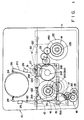
- FIG. 1 shows a magnetic recording/reproducing apparatus according to an embodiment of this invention.
- a main chassis 10 has a cassette container 11 on one side thereof.
- a feed reel table 13 and a take-up reel table 14 of a tape run system are arranged with a predetermined distance therebetween in the cassette container 11.
- a feed reel 12a and a take-up reel 12b of a first tape cassette 12 are mounted on the tables 13 and 14.
- the feed reel table 13 is brought into contact with a distal end portion of a movable arm 15.
- a base part of the feed reel table 13 is attached to a drive shaft of a direct-coupled motor 16.
- a shaft 15a is rotatably supported by a proximal end portion of the movable arm 15.
- a gear portion section 17 is arranged in the vicinity of the shaft 15a.
- One end portion of a gear motion transmitting mechanism 18 or a torque transmitting mechanism is meshed with the gear portion 17, and the other end portion of the mechanism 18 is meshed with a drive gear 20.
- the drive gear 20 is engaged with a drive shaft of a drive motor 19.
- the movable arm 15 is driven by means of the motor 19 via the drive gear 20 and the gear motion transmitting mechanism 18.
- the feed reel table 13 is moved between a first position (indicated by a broken line in Fig.
- a feed reel 21a of a second tape cassette 21 (e.g. a VHSC-cassette, indicated by a solid line) is to be located.
- a base part of the take-up reel table 14 is coupled to a direct-coupled motor 22.
- a gear portion 14a is formed on the periphery of the take-up reel table 14.
- One end portion of a gear motion transmitting mechanism 23 or a torque transmitting mechanism is meshed with the gear portion 14a.
- the other end portion of the mechanism 23 is removably meshed with a take-up gear 21b attached to a take-up reel 21d of the C-cassette 21. Consequently, the torque of the take-up reel table 14 is transmitted, alternatively, to the take-up gear 21b of the C-cassette 21, thereby rotating the take-up reel 21d.
- the main chassis 10 has a cylinder 24 functioning as a tape drive mechanism.
- An erase head 25, a voice control head 26, and a capstan 27 are arranged to face the cylinder 24.
- the main chassis 10 is also provided with an entrance-side post member 28 and an exit side post member 29 which constitute a tape loading mechanism.
- the post members 28 and 29 are movable between a loading start position and a loading end position. In the loading start position, the post members 28 and 29 are situated in recesses 21e of each of the full-size cassette 12 and the C-cassette 21. In the loading end position, the post members 28 and 29 are situated on both sides of the cylinder 24.
- a guide member 30 is movably arranged on the chassis 10 so as to face the take-up reel 12b of the full-size cassette 12.
- the entrance-side post member 28 and exit-side post member 29 are driven by a tape loading drive unit (not shown) to the loading end position in which a tape 12c (21c) of the full-size cassette 12 (or C-cassette 21) is pulled and set onto the cylinder 24.
- the tape loading drive unit is operated in the reverse direction, the tape 12c (21c) is restored to the loading start position in which the tape 12c (21c) is contained in the cassette 22 (21).
- the guide member 30 is driven, along with the entrance-side post member 28 and the exit-side post member 29, by means of the tape loading drive unit.
- the guide member 30 sets the tape 12c of the full-size cassette 12 to a predetermined position.
- a pinch roller 31 is rotatably attached to the chassis 10.
- the pinch roller 31 is moved in interlock with a pinch lever (not shown) driven by the tape loading drive unit, thereby clamping the tape 12c (21c) between itself and the capstan 27.
- a tension applying post 32 is moved in interlock with the tape loading drive unit, thereby applying a suitable tension to the tape 12c (21c).
- Fig. 2 shows the state wherein the full-size cassette 12 has been loaded in the cassette container 11.
- the motor 19 is first actuated to shift the feed reel table 13 to the first position in the clockwise direction via the gear motion transmitting mechanism 18 and the movable arm 15.
- the cassette container 11 is set in the state for loading the full-size cassette.
- the full-size cassette 12 is mounted on the feed reel table 13 and the take-up reel table 14
- its recesses 12d contain the capstan 27, entrance-side post member 28, exit-side post member 29, and tension applying post 32.
- the post members 28 and 29, the pinch roller 31, and the tension applying post 32 are moved by the tape loading drive unit so as to pull the cape 12c and pass it over the cylinder 24.
- the motors 16 and 22 coupled to the feed reel table 13 and take-up reel table 14 are driven in accordance with a selected operation mode, and the tape in the full-size cassette 12c is run.
- the tape loading drive unit When the tape loading drive unit is actuated in the reverse direction, the post members 28 and 29, the pinch roller 31, and the tension applying post 32 are shifted to the loading start position. Also, the reel tables 13 and 14 are rotated by the motors 16 and 22. Thus, the tape 12c passed over the cylinder 24 is restored in the cassette 12.
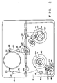
- Fig. 3 shows the state wherein the C-cassette 21 has been loaded in the cassette container 11.
- the motor 19 is first driven to shift the feed reel table 13 to the second position in the counterclockwise direction via the gear motion transmitting mechanism 18 and the movable arm 15.
- the cassette container 11 is set in the state for loading the C-cassette.
- the feed reel 21a of the C-cassette 21 is mounted on the freed reel table 13.
- the take-up gear 21b of C-cassette 21 is meshed with the gear 14a of the take-up reel table 14 via the gear motion transmitting mechanism 23.
- the recesses 21e of the C-cassette 21 contain the capstan 26, entrance-side post member 28, exit-side post member 29, and tension applying post 32.
- the post members 28 and 29, the pinch roller 31, and the tension applying post 32 are moved by the tape loading drive unit so as to pull the cape 21c and pass it over the cylinder 24.
- the motors 16 and 22 coupled to the feed reel table 13 and take-up reel table 14 are driven in accordance with a selected operation mode, and the tape in the C-cassette 21 is run.
- the feed reel 21a is driven directly by the feed reel table 13, while the take-up reel 21d is driven via the gear motion transmitting mechanism 23.
- the torque of the take-up reel table 14 is transmitted to the take-up gear 21b of the take-up reel 21d via the gear motion transmitting mechanism 23.
- the tape loading drive unit When the tape loading drive unit is actuated in the reverse direction, the post members 28 and 29, the pinch roller 31, and the tension applying post 32 are shifted to the loading start position. Also, the reel tables 13 and 14 are rotated by the motors 16 and 22. The feed reel 21a of the C-cassette 21 is driven directly by the feed reel table 13, while the take-up reel 21d is driven via the gear motion transmitting mechanism 23. The torque of the take-up reel table 14 is transmitted to the take-up gear 21b of the take-up reel 21d via the gear motion transmitting mechanism 28. Thus, the tape 12c passed over the cylinder 24 is restored in the cassette 12.
- the feed reel 12a and take-up reel 12b of the full-size cassette 12 are mounted on the feed reel table 13 and take-up reel table 14, and the tape of the the full-size cassette 12 is run.
- the feed reel 21a of the C-cassette 21 is mounted on the feed reel table 13, and the torque of the take-up reel table 14 is transmitted to the take-up reel 21d via the gear motion transmitting mechanism 23.
- the tape of the C-cassette 21 is run.
- the tape of the C-cassette 21 can be run without any adapter, by using the feed reel table 13 and the take-up reel table 14 which are used to run the tape of the full-size cassette 12. Namely, both the full-size cassette 12 and the C-cassette 21 can be set in the VTR without using the C-cassette adapter, and the troublesome procedure of setting the C-cassette can be avoided.
- the feed reel table 13 is movable between the first position where the feed reel 12a of the full-size cassette 12 is mounted and the second position where the feed reel 21a of the C-cassette 21 is mounted. Further, the gear motion transmitting mechanism 23 is provided for transmitting the torque of the take-up reel table 14 to the take-up reel 21d of the C-cassette 21.
- the full-size cassette 12 In the state wherein the feed reel table 13 is situated in the first position, the full-size cassette 12 can be mounted.
- the feed reel 21a of the C-cassette 21 is rotated along with the table 13, and the take-up gear 21b of the take-up reel 21d is rotated by means of the gear motion transmitting mechanism 23.
Landscapes
- Replacement Of Web Rolls (AREA)
- Automatic Tape Cassette Changers (AREA)
- Unwinding Webs (AREA)
Applications Claiming Priority (2)
| Application Number | Priority Date | Filing Date | Title |
|---|---|---|---|
| JP131851/89 | 1989-05-25 | ||
| JP1131851A JPH02310850A (ja) | 1989-05-25 | 1989-05-25 | 磁気記録再生装置 |
Publications (3)
| Publication Number | Publication Date |
|---|---|
| EP0399497A2 true EP0399497A2 (de) | 1990-11-28 |
| EP0399497A3 EP0399497A3 (de) | 1991-01-02 |
| EP0399497B1 EP0399497B1 (de) | 1995-02-15 |
Family
ID=15067601
Family Applications (1)
| Application Number | Title | Priority Date | Filing Date |
|---|---|---|---|
| EP90109805A Expired - Lifetime EP0399497B1 (de) | 1989-05-25 | 1990-05-23 | Magnetisches Aufzeichnungs-/Wiedergabegerät, in welches Bandkassetten verschiedener Grössen geladen werden können |
Country Status (5)
| Country | Link |
|---|---|
| US (1) | US5105319A (de) |
| EP (1) | EP0399497B1 (de) |
| JP (1) | JPH02310850A (de) |
| KR (1) | KR940001240B1 (de) |
| DE (1) | DE69016830T2 (de) |
Cited By (3)
| Publication number | Priority date | Publication date | Assignee | Title |
|---|---|---|---|---|
| GB2413684A (en) * | 2004-04-30 | 2005-11-02 | Hewlett Packard Development Co | Tape guide assembly for different cartridge formats |
| EP1821077A1 (de) | 2006-02-21 | 2007-08-22 | Metrohm Ag | Volumenmess- und Dosiereinrichtung |
| US9702793B2 (en) | 2015-03-16 | 2017-07-11 | Todd A Balisky | Variable volume sample capture device |
Families Citing this family (5)
| Publication number | Priority date | Publication date | Assignee | Title |
|---|---|---|---|---|
| JPH03295064A (ja) * | 1990-04-13 | 1991-12-26 | Sony Corp | 記録再生装置 |
| JP3208621B2 (ja) * | 1993-07-12 | 2001-09-17 | ソニー株式会社 | 記録再生装置 |
| KR970008618B1 (ko) * | 1994-06-13 | 1997-05-27 | 엘지전자 주식회사 | 릴 시프트 데크 메카니즘에서의 텐션 조절장치 |
| US5519550A (en) * | 1994-11-03 | 1996-05-21 | Yeh; Tsun-Wan | Tape cassette adapter for converting a compact tape cassette to a standard size tape cassette for application in a general video-tape player |
| DE19610006A1 (de) * | 1996-03-14 | 1997-09-18 | Thomson Brandt Gmbh | Vorrichtung zum Laden und Entladen eines Rekorders zur wahlweisen Aufnahme verschiedener Kassettentypen |
Family Cites Families (12)
| Publication number | Priority date | Publication date | Assignee | Title |
|---|---|---|---|---|
| JPS6044740B2 (ja) * | 1980-11-25 | 1985-10-05 | 日本ビクター株式会社 | テ−プカセツト |
| JPS57123573A (en) * | 1981-01-20 | 1982-08-02 | Victor Co Of Japan Ltd | Adapter for tape cassette |
| NL8200181A (nl) * | 1981-01-31 | 1982-08-16 | Victor Company Of Japan | Registreer- en /of reproduceerinrichting. |
| JPS58141481U (ja) * | 1982-03-16 | 1983-09-22 | 日本ビクター株式会社 | テ−プカセツト用アダプタ |
| US4567536A (en) * | 1982-05-31 | 1986-01-28 | Victor Company Of Japan, Ltd. | Adapter for a miniature type tape cassette |
| US4490757A (en) * | 1982-09-09 | 1984-12-25 | Kabushiki Kaisha Welwod | Tape recorder |
| JPS6040545A (ja) * | 1983-08-12 | 1985-03-02 | Sony Corp | カセツト式記録再生装置 |
| CH665195A5 (de) * | 1984-03-30 | 1988-04-29 | Walter Suter | Verfahren und vorrichtung zum aufeinanderfolgenden transport von dokumenten aus einem zweibahnigen ausdruck. |
| JPS6442051A (en) * | 1987-08-07 | 1989-02-14 | Sharp Kk | Magnetic recording and reproducing device |
| JPS63191348A (ja) * | 1987-02-02 | 1988-08-08 | Matsushita Electric Ind Co Ltd | 記録再生装置 |
| JPH077538B2 (ja) * | 1987-02-02 | 1995-01-30 | 松下電器産業株式会社 | 記録再生装置 |
| JPS63214959A (ja) * | 1987-03-03 | 1988-09-07 | Sony Corp | 磁気記録再生装置のカセツト装着機構 |
-
1989
- 1989-05-25 JP JP1131851A patent/JPH02310850A/ja active Pending
-
1990
- 1990-05-23 EP EP90109805A patent/EP0399497B1/de not_active Expired - Lifetime
- 1990-05-23 DE DE69016830T patent/DE69016830T2/de not_active Expired - Fee Related
- 1990-05-23 KR KR1019900007392A patent/KR940001240B1/ko not_active Expired - Fee Related
- 1990-05-24 US US07/528,100 patent/US5105319A/en not_active Expired - Fee Related
Cited By (4)
| Publication number | Priority date | Publication date | Assignee | Title |
|---|---|---|---|---|
| GB2413684A (en) * | 2004-04-30 | 2005-11-02 | Hewlett Packard Development Co | Tape guide assembly for different cartridge formats |
| EP1821077A1 (de) | 2006-02-21 | 2007-08-22 | Metrohm Ag | Volumenmess- und Dosiereinrichtung |
| US7753238B2 (en) | 2006-02-21 | 2010-07-13 | Metrohm Ag | Volume measurement and/or metering device and method for operating a volume measurement and/or metering device |
| US9702793B2 (en) | 2015-03-16 | 2017-07-11 | Todd A Balisky | Variable volume sample capture device |
Also Published As
| Publication number | Publication date |
|---|---|
| EP0399497A3 (de) | 1991-01-02 |
| DE69016830D1 (de) | 1995-03-23 |
| KR940001240B1 (ko) | 1994-02-18 |
| EP0399497B1 (de) | 1995-02-15 |
| JPH02310850A (ja) | 1990-12-26 |
| US5105319A (en) | 1992-04-14 |
| DE69016830T2 (de) | 1995-07-27 |
| KR900019000A (ko) | 1990-12-22 |
Similar Documents
| Publication | Publication Date | Title |
|---|---|---|
| EP0302176B1 (de) | Magnetisches Aufzeichnungs- und Wiedergabegerät | |
| EP0381081B1 (de) | Vorrichtung zum Verhindern der Lockerung eines Kassettenbandes zum Einsatz in einem magnetischen Aufnahme- und Wiedergabegerät | |
| EP0399497A2 (de) | Magnetisches Aufzeichnungs-/Wiedergabegerät, in welches Bandkassetten verschiedener Grössen geladen werden können | |
| JPH061584B2 (ja) | 磁気記録再生装置 | |
| JPH0695418B2 (ja) | カセツト式記録再生装置 | |
| JP3348588B2 (ja) | 記録再生装置 | |
| JP2584071B2 (ja) | 磁気記録再生装置 | |
| JP2954739B2 (ja) | 磁気記録再生装置のカム操作機構 | |
| JPH079728B2 (ja) | 磁気記録再生装置 | |
| KR0139756B1 (ko) | 자기기록재생기의 릴 브레이크장치 | |
| JP3057288B2 (ja) | テープローディング機構 | |
| JPH035007Y2 (de) | ||
| JP2603906B2 (ja) | 記録再生装置 | |
| JPH02260270A (ja) | 磁気記録再生装置 | |
| JPH071580B2 (ja) | テ−プロ−デイング装置 | |
| JPH03162761A (ja) | 磁気記録再生装置 | |
| JPS62120651A (ja) | 磁気記録再生装置 | |
| JPH09237451A (ja) | 記録再生装置 | |
| JPS61188769A (ja) | 磁気記録再生装置 | |
| JPS5880161A (ja) | 磁気記録再生装置 | |
| JPS5968866A (ja) | Vtrのテ−プ装着装置 | |
| JPS5911568A (ja) | 磁気記録再生装置 | |
| JPH02260262A (ja) | テープレコーダ装置 | |
| JPH11306618A (ja) | テープレコーダ | |
| JPS62200568A (ja) | 磁気テ−プ引出機構 |
Legal Events
| Date | Code | Title | Description |
|---|---|---|---|
| PUAI | Public reference made under article 153(3) epc to a published international application that has entered the european phase |
Free format text: ORIGINAL CODE: 0009012 |
|
| PUAL | Search report despatched |
Free format text: ORIGINAL CODE: 0009013 |
|
| 17P | Request for examination filed |
Effective date: 19900620 |
|
| AK | Designated contracting states |
Kind code of ref document: A2 Designated state(s): DE FR GB |
|
| AK | Designated contracting states |
Kind code of ref document: A3 Designated state(s): DE FR GB |
|
| 17Q | First examination report despatched |
Effective date: 19931027 |
|
| GRAA | (expected) grant |
Free format text: ORIGINAL CODE: 0009210 |
|
| AK | Designated contracting states |
Kind code of ref document: B1 Designated state(s): DE FR GB |
|
| REF | Corresponds to: |
Ref document number: 69016830 Country of ref document: DE Date of ref document: 19950323 |
|
| ET | Fr: translation filed | ||
| PLBE | No opposition filed within time limit |
Free format text: ORIGINAL CODE: 0009261 |
|
| STAA | Information on the status of an ep patent application or granted ep patent |
Free format text: STATUS: NO OPPOSITION FILED WITHIN TIME LIMIT |
|
| 26N | No opposition filed | ||
| PGFP | Annual fee paid to national office [announced via postgrant information from national office to epo] |
Ref country code: FR Payment date: 19970513 Year of fee payment: 8 |
|
| PGFP | Annual fee paid to national office [announced via postgrant information from national office to epo] |
Ref country code: GB Payment date: 19970514 Year of fee payment: 8 |
|
| PGFP | Annual fee paid to national office [announced via postgrant information from national office to epo] |
Ref country code: DE Payment date: 19970530 Year of fee payment: 8 |
|
| PG25 | Lapsed in a contracting state [announced via postgrant information from national office to epo] |
Ref country code: GB Free format text: LAPSE BECAUSE OF NON-PAYMENT OF DUE FEES Effective date: 19980523 |
|
| PG25 | Lapsed in a contracting state [announced via postgrant information from national office to epo] |
Ref country code: FR Free format text: LAPSE BECAUSE OF NON-PAYMENT OF DUE FEES Effective date: 19980531 |
|
| GBPC | Gb: european patent ceased through non-payment of renewal fee |
Effective date: 19980523 |
|
| PG25 | Lapsed in a contracting state [announced via postgrant information from national office to epo] |
Ref country code: DE Free format text: LAPSE BECAUSE OF NON-PAYMENT OF DUE FEES Effective date: 19990302 |
|
| REG | Reference to a national code |
Ref country code: FR Ref legal event code: ST |