EP0399080A1 - Silo pour matières pulvérulentes en vrac et procédé pour l'exploitation de tels silos - Google Patents
Silo pour matières pulvérulentes en vrac et procédé pour l'exploitation de tels silos Download PDFInfo
- Publication number
- EP0399080A1 EP0399080A1 EP89109504A EP89109504A EP0399080A1 EP 0399080 A1 EP0399080 A1 EP 0399080A1 EP 89109504 A EP89109504 A EP 89109504A EP 89109504 A EP89109504 A EP 89109504A EP 0399080 A1 EP0399080 A1 EP 0399080A1
- Authority
- EP
- European Patent Office
- Prior art keywords
- silo
- emptying
- channels
- central cone
- outlet
- Prior art date
- Legal status (The legal status is an assumption and is not a legal conclusion. Google has not performed a legal analysis and makes no representation as to the accuracy of the status listed.)
- Withdrawn
Links
- 238000000034 method Methods 0.000 title claims description 13
- 239000000463 material Substances 0.000 claims description 10
- 238000011144 upstream manufacturing Methods 0.000 claims 1
- 238000005516 engineering process Methods 0.000 abstract description 3
- 239000013590 bulk material Substances 0.000 description 17
- 238000009423 ventilation Methods 0.000 description 10
- 235000012054 meals Nutrition 0.000 description 8
- 239000004568 cement Substances 0.000 description 7
- 230000008569 process Effects 0.000 description 7
- 230000000694 effects Effects 0.000 description 5
- VTYYLEPIZMXCLO-UHFFFAOYSA-L Calcium carbonate Chemical compound [Ca+2].[O-]C([O-])=O VTYYLEPIZMXCLO-UHFFFAOYSA-L 0.000 description 4
- 238000004519 manufacturing process Methods 0.000 description 4
- 230000005484 gravity Effects 0.000 description 3
- 230000008901 benefit Effects 0.000 description 2
- 230000015572 biosynthetic process Effects 0.000 description 2
- 229910000019 calcium carbonate Inorganic materials 0.000 description 2
- 235000010216 calcium carbonate Nutrition 0.000 description 2
- 230000008859 change Effects 0.000 description 2
- 235000013312 flour Nutrition 0.000 description 2
- 238000005755 formation reaction Methods 0.000 description 2
- 238000000227 grinding Methods 0.000 description 2
- 238000009434 installation Methods 0.000 description 2
- 239000000203 mixture Substances 0.000 description 2
- 230000008439 repair process Effects 0.000 description 2
- 235000008733 Citrus aurantifolia Nutrition 0.000 description 1
- 235000011941 Tilia x europaea Nutrition 0.000 description 1
- 241000722921 Tulipa gesneriana Species 0.000 description 1
- 238000009825 accumulation Methods 0.000 description 1
- 238000005273 aeration Methods 0.000 description 1
- 239000011230 binding agent Substances 0.000 description 1
- 238000007906 compression Methods 0.000 description 1
- 239000012141 concentrate Substances 0.000 description 1
- 238000013016 damping Methods 0.000 description 1
- 238000009826 distribution Methods 0.000 description 1
- 230000005611 electricity Effects 0.000 description 1
- 238000011156 evaluation Methods 0.000 description 1
- 239000004744 fabric Substances 0.000 description 1
- 230000002349 favourable effect Effects 0.000 description 1
- 238000010304 firing Methods 0.000 description 1
- 239000010881 fly ash Substances 0.000 description 1
- 230000006872 improvement Effects 0.000 description 1
- 238000007689 inspection Methods 0.000 description 1
- 239000004571 lime Substances 0.000 description 1
- 239000011148 porous material Substances 0.000 description 1
- 239000002994 raw material Substances 0.000 description 1
- 230000001105 regulatory effect Effects 0.000 description 1
- 238000005204 segregation Methods 0.000 description 1
- 238000003860 storage Methods 0.000 description 1
- 239000011232 storage material Substances 0.000 description 1
- 238000013517 stratification Methods 0.000 description 1
- 239000000126 substance Substances 0.000 description 1
Images


Classifications
-
- B—PERFORMING OPERATIONS; TRANSPORTING
- B65—CONVEYING; PACKING; STORING; HANDLING THIN OR FILAMENTARY MATERIAL
- B65D—CONTAINERS FOR STORAGE OR TRANSPORT OF ARTICLES OR MATERIALS, e.g. BAGS, BARRELS, BOTTLES, BOXES, CANS, CARTONS, CRATES, DRUMS, JARS, TANKS, HOPPERS, FORWARDING CONTAINERS; ACCESSORIES, CLOSURES, OR FITTINGS THEREFOR; PACKAGING ELEMENTS; PACKAGES
- B65D88/00—Large containers
- B65D88/54—Large containers characterised by means facilitating filling or emptying
- B65D88/72—Fluidising devices
Definitions
- the invention relates to a silo according to the preamble of claim 1 and a method for operating such a silo.
- a silo according to the preamble of claim 1 is known from DE-A-23 52 455.
- EP-A 123 031 also belongs to the prior art.
- Silos of this type are used for the storage and equalization of, for example, cement, cement raw meal, ground lime, fly ash and various other binders.
- the silos have several outlet openings, which are arranged at the same angle to each other at the level of the loosening base on the central cone. Such silos are manufactured with and without a ring embankment and are given different loosening areas with a correspondingly variable number of silo outlet connections.
- the loosening units usually consist of air troughs.
- Each outlet nozzle is equipped with a shut-off and dosing device.
- a comparatively low-compressed air is blown in in a limited amount, so that the emptying and mixing process is carried out with substantial use of the gravity and flowability of the bulk material.
- the invention has for its object to provide a silo according to the preamble of claim 1 and a corresponding method for its operation, in which the mixing function is improved without thereby incurring higher costs in the creation and operation.
- the number of conveyor troughs leading to the collector and the outlet housing does not increase, it is even possible to reduce the number of these components.
- the mixing is significantly improved, since the number of so-called "emptying and mixing drums" is increased and these drums are distributed in a particularly effective manner in the silo space and arranged with respect to one another.
- the trumpets When emptying and changing the ventilation of the individual stages, the trumpets are inevitably constantly changed in their base position by rotating on two ring base lines, an inner and an outer one.
- the radial discharge lines are used as double-level emptying channels educated.
- the troughs on the ring base which are closer to the central cone, are assigned to the overhead air troughs (without step). They are ventilated together with the associated discharge trough in alternation of the individual sections and, when the silo outlet is open, generate a corresponding emptying flow that starts from the cross section of the upper housing outlet at the central cone.
- the overhead air channel with the channels assigned to it remains unvented in the frictional engagement on the ring silo floor, so that no bulk material can flow out of this level.
- the bulk material loosened from the lower level accumulates in front of the common metering slide and, due to its liquid-like state, naturally rises into the upper short delivery channel.
- the metering slide is controlled in a known manner in order to remove the desired flow of material in a controlled manner.
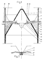
- the silo interior is designated by 1 in FIG.
- This silo interior is delimited by the silo wall 2, the central cone 3, an annular slope 4 and an annular base 5.
- the ring base 5 is covered with air conveyor troughs 6, which have an inclination up to the air conveyor troughs 7 of the upper stage of the double-level emptying channel 8.
- the lower stage is formed by air conveyor channels 9.
- the upper and lower stages of each emptying channel 8 open into an outlet housing 10.
- Conveyor troughs 11 lead into a collector 21.
- Metering slides 12 are arranged behind the upper inlet in each conveyor trough 11.
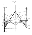
- Fig. 2 is clearly the two-story design of the drainage channel 8 with the air troughs 7 of the upper Stage and the air troughs 9 of the lower stage recognizable.
- the ring base 5 is also covered with air troughs 6.
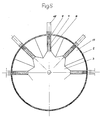
- FIG. 3 the air channels 7 and 9 of the upper and lower stage can be seen.
- the ring base 5, which is occupied by the air conveying channels 6, is delimited by a ring embankment 5 and the central cone 3. Additional slides 15 serve to close the material inlet openings 16.
- FIGS. 1 and 2 it is clear that the upper air feed channels 7 are shorter in the longitudinal direction than the lower air feed channels 9, so that the material inlet opening 16 is formed through which the material enters the lower one Stage reached.
- raw meal for cement production is selected as bulk material.
- Silos of the type described have the function of ensuring a sufficient supply of flour and of mixing the bulk material, which is subject to chemical and physical fluctuations in composition, that is to say raw meal.
- the raw material is continuously milled by the raw meal mill and only fed into the silo.
- the flour flow is divided above the silo ceiling and fed to the silo in partial flows via star-shaped air conveying troughs. This measure avoids segregation tendencies during the free fall in the silo space and achieves an approximately uniform horizontal stratification of the compositional fluctuations which naturally still exist in the bulk material. Layers are alternately built up with higher and lower concentration measures.
- the calcium carbonate content, CaCO3 content is preferably analyzed as a measure of concentration for homogeneity and used as an evaluation or control variable. Both for the after the silo Firing process to be carried out in the rotary kiln as well as for the cement quality are essential to a minimum reduced composition fluctuations.
- the silo feed is only interrupted when the furnace is at a standstill or there is excess grinding capacity, for example in order to bridge repairs or to be able to take advantage of favorable electricity tariffs for day or night grinding operations.
- Level differences in the silo can also occur if only the continuous emptying process is operated temporarily and not the silo loading.
- the silo emptying should now be operated in such a way that the layer formations described above flow into one another as intensively as possible, so that the fluctuations around the mean value to be calculated are as small as possible, i.e. are only recognizable in the range of the measuring error limits.
- the ring silo floor 5, which is covered with air conveying channels 6, is divided into several sections, of which only one is ventilated at a time. Aeration with a low-compression air is based on a rotary lobe blower. The air penetrates the porous medium, a special fabric with which the conveyor troughs are covered, and, finely divided, reaches the lower bed layer. The frictional engagement is released, the pore volume in the raw meal of this lower bed layer increases and only for the relatively small controlled section area is raw meal converted into a liquid-like state, which lasts as long as the controlled section is blown with loosening air.
- each silo outlet has a front ventilation section located on the cone and a rear ventilation section located on the silo wall.
- the opening program of the metering slide 12 is also controlled in parallel.
- the channels 6 adjacent to the central cone 3 belong to the ventilation of the upper step 7 of the emptying channel 8, the channels 6 closer to the silo wall 2 and the ring embankment 4 belong to the lower step 9.
- the two ventilation sections 7 and 6 or 9 and 6 belonging to each silo outlet 10 are aerated one after the other.
- the bulk material above is now inevitably conveyed into the outlet housing when the associated metering slide 12 is open, either directly via the front and top outlet cross-section of the outlet housing 10 or via the rear inlet cross-section 16.
- the bulk material is dosed from the silo according to the furnace capacity with volume flows of ⁇ 50 to ⁇ 300m3 / h and removed continuously.
- the internal ventilation change has no influence on the continuous drain flow.
- the intensity of the mass exchange is decisive for the mixing effect in the layer formations. Since it is a matter of gravity mixing in the emptying streams also referred to as mixing drums, the inevitably guided and constantly changing drum base according to the invention is of particular importance.
- the device shape of the silo bottom in alternation of the sections, causes the bulk material to flow off over two circular base lines, an inner one at the central cone 3 and an outer one at the silo wall 2. Dead or passive bulk goods zones cannot arise. Flow profiles are actually created that cover the entire silo content. The mass exchange is expanded and the mixing effect is increased.
- the outlet housing 10 work due to sufficient length of coverage as a friction lock for the upper stage of the drainage channel with the air troughs 7, provided that there is no ventilation for this area. There will therefore be no short-circuit currents.
- the lower stage of the emptying channels with the air conveyor channels 9 work with an open inlet cross section 16 for the bulk material in the non-ventilated state as a friction lock, so that it is prevented that at the same time the bulk material loosening by the air conveyor channel 7 of the upper stage with the adjacent air conveyor channels 6 also unventilated bulk material from the rear Silo wall area reaches the discharge housing 10 via the air conveyor channel 9 of the lower stage.
Landscapes
- Engineering & Computer Science (AREA)
- Mechanical Engineering (AREA)
- Filling Or Emptying Of Bunkers, Hoppers, And Tanks (AREA)
Priority Applications (1)
| Application Number | Priority Date | Filing Date | Title |
|---|---|---|---|
| EP89109504A EP0399080A1 (fr) | 1989-05-26 | 1989-05-26 | Silo pour matières pulvérulentes en vrac et procédé pour l'exploitation de tels silos |
Applications Claiming Priority (1)
| Application Number | Priority Date | Filing Date | Title |
|---|---|---|---|
| EP89109504A EP0399080A1 (fr) | 1989-05-26 | 1989-05-26 | Silo pour matières pulvérulentes en vrac et procédé pour l'exploitation de tels silos |
Publications (1)
| Publication Number | Publication Date |
|---|---|
| EP0399080A1 true EP0399080A1 (fr) | 1990-11-28 |
Family
ID=8201410
Family Applications (1)
| Application Number | Title | Priority Date | Filing Date |
|---|---|---|---|
| EP89109504A Withdrawn EP0399080A1 (fr) | 1989-05-26 | 1989-05-26 | Silo pour matières pulvérulentes en vrac et procédé pour l'exploitation de tels silos |
Country Status (1)
| Country | Link |
|---|---|
| EP (1) | EP0399080A1 (fr) |
Cited By (5)
| Publication number | Priority date | Publication date | Assignee | Title |
|---|---|---|---|---|
| EP0550778A1 (fr) * | 1992-01-08 | 1993-07-14 | Werner Krauss | Silo pour le stockage et mélange de matières en vrac pulvérulentes, à grains fins, et fluidisables |
| CN105536627A (zh) * | 2015-12-02 | 2016-05-04 | 常熟浦发第二热电能源有限公司 | 一种飞灰均化库及其使用方法 |
| CN111470198A (zh) * | 2020-03-20 | 2020-07-31 | 靖江市亚泰物流装备有限公司 | 一种粉料罐式集装箱的流化装置 |
| CN112978293A (zh) * | 2021-04-27 | 2021-06-18 | 成都光华科技发展有限公司 | 一种可实现计量均匀送粉的超细高纯微粉体送粉器 |
| CN113548424A (zh) * | 2021-08-12 | 2021-10-26 | 珀挺机械工业(厦门)有限公司 | 一种可实现料打料的耐磨料道结构、分料机构 |
Citations (4)
| Publication number | Priority date | Publication date | Assignee | Title |
|---|---|---|---|---|
| CH399324A (de) * | 1963-03-05 | 1965-09-15 | Buehler Ag Geb | Silo für Schüttgüter |
| DE2121616B2 (de) * | 1971-05-03 | 1974-11-14 | Claudius Peters Ag, 2000 Hamburg | Vorrichtung zum Mischen von Schüttgut und Verfahren zu ihrem Betrieb |
| DE3033270A1 (de) * | 1980-09-04 | 1982-04-01 | Ibau Hamburg Ingenieurgesellschaft Industriebau Mbh, 2000 Hamburg | Silo fuer mehlfoermige schuettgueter, insbesondere zement |
| DE3243222A1 (de) * | 1982-11-23 | 1984-05-24 | Ibau Barcelona S.A., Barcelona | Grossraumsilo fuer schuettgut, insbesondere zementrohmehl |
-
1989
- 1989-05-26 EP EP89109504A patent/EP0399080A1/fr not_active Withdrawn
Patent Citations (4)
| Publication number | Priority date | Publication date | Assignee | Title |
|---|---|---|---|---|
| CH399324A (de) * | 1963-03-05 | 1965-09-15 | Buehler Ag Geb | Silo für Schüttgüter |
| DE2121616B2 (de) * | 1971-05-03 | 1974-11-14 | Claudius Peters Ag, 2000 Hamburg | Vorrichtung zum Mischen von Schüttgut und Verfahren zu ihrem Betrieb |
| DE3033270A1 (de) * | 1980-09-04 | 1982-04-01 | Ibau Hamburg Ingenieurgesellschaft Industriebau Mbh, 2000 Hamburg | Silo fuer mehlfoermige schuettgueter, insbesondere zement |
| DE3243222A1 (de) * | 1982-11-23 | 1984-05-24 | Ibau Barcelona S.A., Barcelona | Grossraumsilo fuer schuettgut, insbesondere zementrohmehl |
Cited By (6)
| Publication number | Priority date | Publication date | Assignee | Title |
|---|---|---|---|---|
| EP0550778A1 (fr) * | 1992-01-08 | 1993-07-14 | Werner Krauss | Silo pour le stockage et mélange de matières en vrac pulvérulentes, à grains fins, et fluidisables |
| CN105536627A (zh) * | 2015-12-02 | 2016-05-04 | 常熟浦发第二热电能源有限公司 | 一种飞灰均化库及其使用方法 |
| CN111470198A (zh) * | 2020-03-20 | 2020-07-31 | 靖江市亚泰物流装备有限公司 | 一种粉料罐式集装箱的流化装置 |
| CN112978293A (zh) * | 2021-04-27 | 2021-06-18 | 成都光华科技发展有限公司 | 一种可实现计量均匀送粉的超细高纯微粉体送粉器 |
| CN112978293B (zh) * | 2021-04-27 | 2023-09-15 | 成都光华科技发展有限公司 | 一种可实现计量均匀送粉的超细高纯微粉体送粉器 |
| CN113548424A (zh) * | 2021-08-12 | 2021-10-26 | 珀挺机械工业(厦门)有限公司 | 一种可实现料打料的耐磨料道结构、分料机构 |
Similar Documents
| Publication | Publication Date | Title |
|---|---|---|
| DE2205716A1 (de) | Aufgabevorrichtung für Schüttgut | |
| DE2121616C3 (de) | Vorrichtung zum Mischen von Schüttgut und Verfahren zu Ihrem Betrieb | |
| EP0294428B1 (fr) | Deversement par cylindres | |
| DE60015391T2 (de) | Vorrichtung zur gleichmässigen zufuhr von pulver zu einem konzentratbrenner eines suspensionsschmelzofens | |
| DE3626053C2 (fr) | ||
| EP0399080A1 (fr) | Silo pour matières pulvérulentes en vrac et procédé pour l'exploitation de tels silos | |
| DE2724928C2 (de) | Großraumsilo für mehlförmiges Schüttgut | |
| EP0144507A2 (fr) | Silo avec deux chambres à mélange | |
| EP0592368B1 (fr) | Installation de compostage | |
| DE3117313C2 (de) | Auslauftrichter für Silozellen | |
| DE2727499A1 (de) | Silo fuer schuettgut | |
| EP0303864B1 (fr) | Silo pour matières en vrac pulvérulentes et à grains serrés | |
| DE2657596C2 (de) | Mischkammersilo für Schüttgut | |
| EP0550778B1 (fr) | Silo pour le stockage et mélange de matières en vrac pulvérulentes, à grains fins, et fluidisables | |
| DE3404804A1 (de) | Vertikaldarre | |
| DE4138912A1 (de) | Vorrichtung zur herstellung von vorgemischten baustoffen | |
| DE4328314A1 (de) | Misch- und Vorratssilo für staubförmige Schüttgüter | |
| DE2827991A1 (de) | Schuettgutsilo mit mischkammer | |
| DE2208247C2 (de) | Verfahren und Vorrichtung für die Wärmeübertragung zwischen pulverförmigem Material und Gas | |
| DE3515976C2 (de) | Wendelrutscheneinbau für Zwischenbunker des Untertagebergbaus | |
| AT303625B (de) | Verfahren zum Mischen von Schüttgut in einem Mischsilo | |
| DE3224196A1 (de) | Verfahren zum mischen von feingut | |
| DE3626120C2 (fr) | ||
| AT219632B (de) | Drehbare Begichtungseinrichtung eines Schachtes, insbesondere eines Schachtofens | |
| DE8222989U1 (de) | Siebkasten zur sortierung bzw. reinigung von getreide, saemereien und aehnlichem nutzgut |
Legal Events
| Date | Code | Title | Description |
|---|---|---|---|
| PUAI | Public reference made under article 153(3) epc to a published international application that has entered the european phase |
Free format text: ORIGINAL CODE: 0009012 |
|
| AK | Designated contracting states |
Kind code of ref document: A1 Designated state(s): AT BE CH DE ES FR GB GR IT LI LU NL SE |
|
| 17P | Request for examination filed |
Effective date: 19901127 |
|
| STAA | Information on the status of an ep patent application or granted ep patent |
Free format text: STATUS: THE APPLICATION HAS BEEN WITHDRAWN |
|
| 17Q | First examination report despatched |
Effective date: 19920511 |
|
| 18W | Application withdrawn |
Withdrawal date: 19920609 |