EP0397193A2 - Outil de coupe rotatif - Google Patents
Outil de coupe rotatif Download PDFInfo
- Publication number
- EP0397193A2 EP0397193A2 EP90108911A EP90108911A EP0397193A2 EP 0397193 A2 EP0397193 A2 EP 0397193A2 EP 90108911 A EP90108911 A EP 90108911A EP 90108911 A EP90108911 A EP 90108911A EP 0397193 A2 EP0397193 A2 EP 0397193A2
- Authority
- EP
- European Patent Office
- Prior art keywords
- cutter body
- forward end
- face
- chip
- cutting tool
- Prior art date
- Legal status (The legal status is an assumption and is not a legal conclusion. Google has not performed a legal analysis and makes no representation as to the accuracy of the status listed.)
- Granted
Links
- 230000002093 peripheral effect Effects 0.000 claims abstract description 182
- 230000033001 locomotion Effects 0.000 claims description 9
- 238000003825 pressing Methods 0.000 claims description 3
- 238000003801 milling Methods 0.000 description 55
- 230000007246 mechanism Effects 0.000 description 34
- 238000012545 processing Methods 0.000 description 33
- 230000004048 modification Effects 0.000 description 21
- 238000012986 modification Methods 0.000 description 21
- 230000008901 benefit Effects 0.000 description 18
- 230000006866 deterioration Effects 0.000 description 7
- 239000000463 material Substances 0.000 description 6
- 238000000034 method Methods 0.000 description 5
- 230000009467 reduction Effects 0.000 description 5
- 230000008859 change Effects 0.000 description 4
- 230000009471 action Effects 0.000 description 3
- 238000005452 bending Methods 0.000 description 3
- 239000010730 cutting oil Substances 0.000 description 3
- 238000007599 discharging Methods 0.000 description 3
- 230000000694 effects Effects 0.000 description 3
- 230000008569 process Effects 0.000 description 3
- 238000007667 floating Methods 0.000 description 2
- 238000003780 insertion Methods 0.000 description 2
- 230000037431 insertion Effects 0.000 description 2
- 230000000717 retained effect Effects 0.000 description 2
- 229910001209 Low-carbon steel Inorganic materials 0.000 description 1
- 238000009825 accumulation Methods 0.000 description 1
- 230000004075 alteration Effects 0.000 description 1
- 238000013459 approach Methods 0.000 description 1
- 238000010276 construction Methods 0.000 description 1
- 230000000994 depressogenic effect Effects 0.000 description 1
- 239000000428 dust Substances 0.000 description 1
- 231100001261 hazardous Toxicity 0.000 description 1
- 230000001771 impaired effect Effects 0.000 description 1
- 230000009545 invasion Effects 0.000 description 1
- 238000012423 maintenance Methods 0.000 description 1
- 239000003921 oil Substances 0.000 description 1
- 238000007789 sealing Methods 0.000 description 1
Images


Classifications
-
- B—PERFORMING OPERATIONS; TRANSPORTING
- B23—MACHINE TOOLS; METAL-WORKING NOT OTHERWISE PROVIDED FOR
- B23Q—DETAILS, COMPONENTS, OR ACCESSORIES FOR MACHINE TOOLS, e.g. ARRANGEMENTS FOR COPYING OR CONTROLLING; MACHINE TOOLS IN GENERAL CHARACTERISED BY THE CONSTRUCTION OF PARTICULAR DETAILS OR COMPONENTS; COMBINATIONS OR ASSOCIATIONS OF METAL-WORKING MACHINES, NOT DIRECTED TO A PARTICULAR RESULT
- B23Q11/00—Accessories fitted to machine tools for keeping tools or parts of the machine in good working condition or for cooling work; Safety devices specially combined with or arranged in, or specially adapted for use in connection with, machine tools
- B23Q11/0042—Devices for removing chips
- B23Q11/0046—Devices for removing chips by sucking
-
- B—PERFORMING OPERATIONS; TRANSPORTING
- B23—MACHINE TOOLS; METAL-WORKING NOT OTHERWISE PROVIDED FOR
- B23Q—DETAILS, COMPONENTS, OR ACCESSORIES FOR MACHINE TOOLS, e.g. ARRANGEMENTS FOR COPYING OR CONTROLLING; MACHINE TOOLS IN GENERAL CHARACTERISED BY THE CONSTRUCTION OF PARTICULAR DETAILS OR COMPONENTS; COMBINATIONS OR ASSOCIATIONS OF METAL-WORKING MACHINES, NOT DIRECTED TO A PARTICULAR RESULT
- B23Q11/00—Accessories fitted to machine tools for keeping tools or parts of the machine in good working condition or for cooling work; Safety devices specially combined with or arranged in, or specially adapted for use in connection with, machine tools
- B23Q11/08—Protective coverings for parts of machine tools; Splash guards
-
- B—PERFORMING OPERATIONS; TRANSPORTING
- B23—MACHINE TOOLS; METAL-WORKING NOT OTHERWISE PROVIDED FOR
- B23Q—DETAILS, COMPONENTS, OR ACCESSORIES FOR MACHINE TOOLS, e.g. ARRANGEMENTS FOR COPYING OR CONTROLLING; MACHINE TOOLS IN GENERAL CHARACTERISED BY THE CONSTRUCTION OF PARTICULAR DETAILS OR COMPONENTS; COMBINATIONS OR ASSOCIATIONS OF METAL-WORKING MACHINES, NOT DIRECTED TO A PARTICULAR RESULT
- B23Q3/00—Devices holding, supporting, or positioning work or tools, of a kind normally removable from the machine
- B23Q3/02—Devices holding, supporting, or positioning work or tools, of a kind normally removable from the machine for mounting on a work-table, tool-slide, or analogous part
- B23Q3/06—Work-clamping means
- B23Q3/069—Work-clamping means for pressing workpieces against a work-table
-
- B—PERFORMING OPERATIONS; TRANSPORTING
- B23—MACHINE TOOLS; METAL-WORKING NOT OTHERWISE PROVIDED FOR
- B23Q—DETAILS, COMPONENTS, OR ACCESSORIES FOR MACHINE TOOLS, e.g. ARRANGEMENTS FOR COPYING OR CONTROLLING; MACHINE TOOLS IN GENERAL CHARACTERISED BY THE CONSTRUCTION OF PARTICULAR DETAILS OR COMPONENTS; COMBINATIONS OR ASSOCIATIONS OF METAL-WORKING MACHINES, NOT DIRECTED TO A PARTICULAR RESULT
- B23Q2220/00—Machine tool components
- B23Q2220/008—Rotatable tool holders coupled in parallel to a non rotating accessory
-
- Y—GENERAL TAGGING OF NEW TECHNOLOGICAL DEVELOPMENTS; GENERAL TAGGING OF CROSS-SECTIONAL TECHNOLOGIES SPANNING OVER SEVERAL SECTIONS OF THE IPC; TECHNICAL SUBJECTS COVERED BY FORMER USPC CROSS-REFERENCE ART COLLECTIONS [XRACs] AND DIGESTS
- Y10—TECHNICAL SUBJECTS COVERED BY FORMER USPC
- Y10T—TECHNICAL SUBJECTS COVERED BY FORMER US CLASSIFICATION
- Y10T407/00—Cutters, for shaping
- Y10T407/19—Rotary cutting tool
- Y10T407/1906—Rotary cutting tool including holder [i.e., head] having seat for inserted tool
- Y10T407/1942—Peripherally spaced tools
-
- Y—GENERAL TAGGING OF NEW TECHNOLOGICAL DEVELOPMENTS; GENERAL TAGGING OF CROSS-SECTIONAL TECHNOLOGIES SPANNING OVER SEVERAL SECTIONS OF THE IPC; TECHNICAL SUBJECTS COVERED BY FORMER USPC CROSS-REFERENCE ART COLLECTIONS [XRACs] AND DIGESTS
- Y10—TECHNICAL SUBJECTS COVERED BY FORMER USPC
- Y10T—TECHNICAL SUBJECTS COVERED BY FORMER US CLASSIFICATION
- Y10T407/00—Cutters, for shaping
- Y10T407/24—Cutters, for shaping with chip breaker, guide or deflector
-
- Y—GENERAL TAGGING OF NEW TECHNOLOGICAL DEVELOPMENTS; GENERAL TAGGING OF CROSS-SECTIONAL TECHNOLOGIES SPANNING OVER SEVERAL SECTIONS OF THE IPC; TECHNICAL SUBJECTS COVERED BY FORMER USPC CROSS-REFERENCE ART COLLECTIONS [XRACs] AND DIGESTS
- Y10—TECHNICAL SUBJECTS COVERED BY FORMER USPC
- Y10T—TECHNICAL SUBJECTS COVERED BY FORMER US CLASSIFICATION
- Y10T409/00—Gear cutting, milling, or planing
- Y10T409/30—Milling
- Y10T409/30392—Milling with means to protect operative or machine [e.g., guard, safety device, etc.]
-
- Y—GENERAL TAGGING OF NEW TECHNOLOGICAL DEVELOPMENTS; GENERAL TAGGING OF CROSS-SECTIONAL TECHNOLOGIES SPANNING OVER SEVERAL SECTIONS OF THE IPC; TECHNICAL SUBJECTS COVERED BY FORMER USPC CROSS-REFERENCE ART COLLECTIONS [XRACs] AND DIGESTS
- Y10—TECHNICAL SUBJECTS COVERED BY FORMER USPC
- Y10T—TECHNICAL SUBJECTS COVERED BY FORMER US CLASSIFICATION
- Y10T409/00—Gear cutting, milling, or planing
- Y10T409/30—Milling
- Y10T409/304088—Milling with means to remove chip
Definitions
- the present invention relates to rotary cutting tools chiefly for use in surface cutting such as, for example, a face milling cutter or the like and, more particularly, to a rotary cutting tool capable of successively processing chips generated during cutting.
- Tools of various configurations have conventionally been proposed as rotatable cutting tools which are used to apply surface processing to a workpiece.
- a tool for use in a face milling cutter is small in cutting resistance and is suitable for strong cutting. Accordingly, the tool for use in the face milling cutter has widely been utilized at present.
- the tool for the face milling cutter comprises a cutter body rotatable about its rotational axis, a plurality of face cutting edges provided at the forward end face of the cutter body, and a plurality of outer peripheral cutting edges provided at a forward end of an outer peripheral surface of the cutter body.
- these edges are made of cemented carbide.
- Almost all mounting methods of the cutting edges use throw-away methods in which at least one carbide tip having the cutting edges is fixedly mounted to the cutting body in a detachable manner.
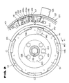
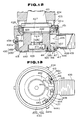
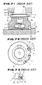
- a cutter body 1 is generally cylindrical in shape and has, at its proximal end, a diameter-reduced section.
- the cutter body 1 has a forward end whose outer periphery is formed with a plurality of recesses or tip mounting grooves 2.
- the tip mounting grooves 2 open toward the forward end of the cutter body 1 and toward a location radially outwardly thereof.
- the tip mounting grooves 2 are equidistantly spaced from each other along the peripheral direction of the cutter body 1.
- a plurality of throw-away tips (hereinafter referred simply to as "tips”) 3 are mounted respectively within the tip mounting grooves 2 by their respective clamp mechanisms 6.
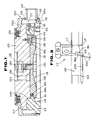
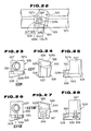
- Each of the clamp mechanisms 6 comprises a wedge element 4 and a clamp screw 5 as shown in Fig. 73.
- the tip 3 is urged against one of a pair of opposed wall surfaces of the tip clamp groove 2, whereby the tip 3 is fixedly mounted in position to the cutter body 1 in a detachable manner.
- the tip 3 is in the form of a plate element made of cemented carbide and is in plan generally square in shape.
- the tip 3 is fixedly mounted in position to the tip mounting groove 2, one end of the tip 3, which projects from the forward end face of the cutter body 1, is formed into a face cutting edge 3a, and one side of the tip 3, which projects from the forward end of the outer peripheral surface of the cutter body 1, is formed into an cutting edge 3b.
- a plurality of tip pockets 7 are provided respectively in front of the tips 3 in the rotational direction of the cutter body 1.
- Each of the tip pockets 7 opens toward the forward end of the cutter body 1 and toward the radially outward location thereof, and has an arcuate wall surface.
- the tip pocket 7 has such a function as to successively guide and discharge chips generated by the cutting edges 3a and 3b, to the outside of the cutter body 1. Further, when a workpiece W is made of material which tends to generate continuous streamline chips such as low carbon steel or the like, the tip pocket 7 has also such a function of continuously rounding off the chips generated, and to divide and to break the chips.
- the diameter-reduced section of the cutter body 1 is fixedly mounted to an arbor 8 through a detent key 9.
- the arbor 8 has a shaft section 8a which is fitted in a mounting bore 10 which is formed at the center of the diameter-reduced section of the cutter body 1.
- a fastening bolt 11 is screwed into the end face of the shaft section 8a from an end face of the diameter-reduced section of the cutter body 1, which is located adjacent a larger-diameter section of the cutter body 1. In this manner, the cutter body 1 is fixedly mounted to the arbor 8 in concentric or coaxial relation thereto.
- the arbor 8 has a tapered shank 8b which is fitted in a tapered bore 12a in a main spindle 12 of a machine tool (hereinafter referred to as "main spindle").
- the tapered shank 8b has its forward end which is formed with a female thread section (not shown).
- the female thread section is provided for drawing or pulling up the arbor 8 axially of the main spindle 12 by means of a drawing bolt (not shown) within the main spindle 12, to firmly connect the face milling cutter and the main spindle 12 to each other.
- Face processing of the workpiece W by the use of the tool for the face milling cutter constructed as above is conducted as follows.
- the taper shank 8b of the arbor 8 is first fitted in the tapered bore 12a of the main spindle 12.
- the arbor 8 is drawn axially of the main spindle 12 by the drawing bolt.
- the arbor 8 is fixedly mounted to the main spindle 12 through a pair of main spindle keys 13.
- the face milling cutter is mounted to the main spindle 12.
- the workpiece W is fixedly mounted to a machine table (not shown) such that a work surface of the workpiece W extends perpendicularly to the axis of the main spindle 12.
- the main spindle 12 is rotated about its axis.
- the main spindle 12 or the machine table is moved axially of the main spindle 12 to give a predetermined depth of cut to the surface of the workpiece W .
- the main spindle 12 or the machine table is moved in a direction perpendicular to the axis of the main spindle 12. By doing so, surface parts of the workpiece W are successively cut by the face cutting edge 3a and the outer peripheral cutting edge 3b of each of the tips 3, so that the workpiece W is subject to surface processing.
- the face milling cutter described above has the following drawback or disadvantage. That is, since the face milling cutter merely guides and discharges the chips generated, peripherally outwardly of the face milling cutter, the chips are widely dispersed or scattered to the circumference of the face milling cutter, accompanied with rotation of the cutter body 1. As a result, not only is the operational environment deteriorated, but also hazardous operating conditions sometimes occur. Further, a considerable time is taken to process the chips after completion of the cutting.
- the conventional face milling cutter has also the following disadvantage. That is, since the chips are gradually accumulated on the workpiece W , the table of the machine or the like, as the cutting continues, thermal deformation occurs in the workpiece W or the machine due to heat of the chips. Thus, working or processing accuracy is deteriorated, and the chips bit into the tip 3 so that the quality of the cut surface is damaged.
- the conventional face milling cutter described above is used to process a joint surface of a box-type workpiece having a relatively thin wall thickness, or to process a workpiece such as an opposite or reverse boss in which portions relatively small in processing area are dotted
- the width of the processing surface extending along the rotational direction of the tool becomes narrower than the peripheral pitch of the tips 3.
- the cutting force fluctuates violently so that sheaves or shakes and vibration are induced.
- intermittent contact between the tips 3 and the workpiece also causes periodical fluctuation in the dynamic rigidity of the main spindle system of the machine to which the tool is mounted.
- the sheaves or shakes and vibration induced by the cutting are amplified to cause breakage of the cutting edges and to reduce the service life thereof and, further, to cause a reduction in the processing accuracy of the workpiece.
- a rotary cutting tool for use with at least one cutting tip having a face
- the rotary cutting tool comprising a cutter body rotatable about a rotational axis and having a forward end and a proximal end, the cutting tip being mounted to an outer periphery of the forward end of the cutter body, and chip suction means arranged outwardly of an outer peripheral surface of the cutter body for drawing chips generated by the cutting tip
- the chip suction means including; generally cylindrical cover means having a wall for covering the cutter body, the cover means being supported by the cutter body for rotation relative thereto; a chip accommodating chamber defined between an inner peripheral surface of the cover means and the outer peripheral surface of the cutter body; suction port means provided in the wall of the cover means and communicating with the chip accommodating chamber; and chip guide means arranged at the forward end of the cutter body in facing relation to the face of the cutting tip for guiding the chips generated by the cutting tip to the chip accommodating chamber.
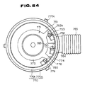
- FIGs. 1 through 3 there is shown a rotary cutting tool according to a first embodiment of the invention.
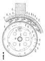
- the rotary cutting tool comprises a cutter body 113 which is formed, at its center, with a central bore 114 extending axially through the cutter body 113.
- the cutter body 113 is generally in the form of a cylinder whose forward end is enlarged in diameter.
- a plurality of recesses or grooves 115 are formed at an outer periphery of the forward end of the cutter body 113 in equidistantly spaced relation to one another in a peripheral direction.
- the grooves 115 open toward a forward end face and an outer peripheral surface of the cutter body 113.
- At least one or a plurality of throw-away tips (hereinafter referred simply to as "tips") 116 are mounted respectively to the grooves 115 through respective cartridges 117 in a detachable manner.
- Each of the tips 116 is in the form of a regular octagon in plan.
- the tip 116 has a face 116a whose ridgelines are formed respectively into cutting edges 118.
- One of the cutting edges 118 of each of the tips 116 slightly projects from the forward end face of the cutter body 113. Further, as shown in Figs.
- outer peripheral surface portions of the cutter body 113 which are contiguous respectively to the grooves 115, are formed respectively into inclined surfaces each of which is gradually inclined radially inwardly of the cutter body 113 toward the face 116a of the tip 116.
- a plurality of tip pockets 119 are formed respectively in front of the faces 116a of the tips 116.
- a chip suction mechanism 120 for removing chips generated by the tips 116 is arranged outwardly of the peripheral surface of the cutter body 113.
- a cutter fastening mechanism 121 for mounting the cutter body 113 to a main spindle (not shown) of a machine body is arranged at a location extending from the central bore 114 to the proximal end of the cutter body 113.
- the chip suction mechanism 120 generally comprises a chip accommodating element or a cover assembly 122 generally in the form of a cylinder for covering the outer peripheral surface of the cutter body 113, a suction port element 123 inserted into a peripheral wall of the cover assembly 122, and a plurality of chip guide members or elements 124 mounted to the forward end face of the cutter body 113.
- the cover assembly 122 is formed, at its proximal end, with a fitting section 122a whose inner periphery is arranged adjacent the proximal end of the cutter body 113.
- the cover assembly 122 is fitted, through a radial bearing 126, about an adapter 125 which forms a part of the cutter fastening mechanism 121.
- the cover assembly 122 is so arranged as to be rotatable relatively to the cutter body 113.
- the cover assembly 122 has its forward end which extends to a location completely covering the cutting edges 118 of the respective tips 116 projecting radially outwardly of the cutter body 113.
- the cover assembly 122 has its inner diameter which is so determined as to be slightly larger than a rotational locus of the above-described cutting edges 118 about the axis of the cutter body 113.
- the cover assembly 122 has an intermediate section contiguous to its forward end, whose inner diameter is so determined as to be identical with that of the forward end of the cover assembly 122.
- the intermediate section has its inner peripheral surface which cooperates with the outer peripheral surface of the cutter body 113 adjacent the proximal end thereof, to define therebetween a chip accommodating chamber 127.
- the suction port element 123 is cylindrical in shape, and has one end thereof which is fitted in the intermediate section of the cover assembly 122.
- the one end of the suction port element 123 has its interior portion which communicates with the chip accommodating chamber 127.
- a suction hose of a suction machine (not shown) is fitted about an outer peripheral surface of the other end of the suction port element 123.
- each of the chip guide elements 124 is in the form of a planar plate, and is fixedly mounted to the cutter body 113 by two mounting screws 128 and 128 at a location facing toward the face 116a of a corresponding one of the tips 116 which are located at the peripheral edge of the forward end of the cutter body 113.
- the chip guide element 124 covers the corresponding tip pocket 119.
- each of the chip guide elements 124 is positioned axially such that its surface is moved rearwardly toward the proximal end of the cutter body 113 with respect to the cutting edge 118 of the tip 116 which projects forwardly of the forward end of the cutter body 113. Further, the chip guide element 124 is positioned peripherally such that a gap t1 occurs between the face 116a of the tip 116 and an end face 124a of the chip guide element 124 facing toward the face 116a of the tip 116. In this manner, the chip guide element 124 guides the chips generated along the face 116a of the tip 116 from the cutting edge 118 thereof, to the tip pocket 119.
- a groove 124b is formed at a portion of the rear face of the chip guide element 124, which faces toward the tip pocket 119, and extends toward the wall surface of the tip pocket 119.
- the cutter fastening mechanism 121 generally comprises the adapter 125 arranged adjacent the proximal end of the cutter body 113, a drive key 130 mounted to the adapter 125, an intermediate element 131 inserted in the central bore 114 of the cutter body 113, and a connecting bolt 132 inserted in the center of the intermediate element 131.
- the adapter 125 is formed, adjacent its proximal end, with a fitting bore 133 in which is inserted a forward end of an arbor (not shown) inserted in a tapered bore in a main spindle of a machine body (not shown).
- a key 134 which is engaged with a key groove (not shown) in a forward end of the main spindle, is formed in a fitting bore 135.
- the adapter 125 is connected to the main spindle in an integral manner by a plurality of connecting bolts (not shown) which are inserted respectively through a plurality of bolt bores 136. Further, the adapter 125 has its outer periphery which is formed with a flange 137.
- the flange 137 has its one end face which faces toward the fitting section 122a of the cover assembly 122 with a slight gap left therebetween, to prevent dirt, dust or the like floating within the chip accommodating chamber 127 from invading the radial bearing 126.
- the adapter 125 is formed, adjacent its forward end, with an annular projection 138 which is fitted in a fitting section 114a of the central bore 114 in the cutter body 113.
- the drive key 130 is fixedly mounted to the annular projection 138 through a bolt 139.
- the drive key 130 is provided for transmitting rotation of the adapter 125 to the cutter body 113.
- the drive key 130 is mounted to the adapter 125 at a location which faces toward inner peripheral surfaces of respective projections or smaller-diameter sections 114b which are formed at the central bore 114 in the cutter body 113.
- the drive key 130 has its forward end which is fitted, in a loose or floating manner, in one of a plurality of cut-outs 140 formed respectively between the smaller-diameter sections 114b in equidistantly spaced relation to each other.
- the drive key 130 is engaged with one of a pair of opposed wall surfaces of one of the cut-outs 140, accompanied with rotation of the cutter body 113.
- the intermediate element 131 is inserted in an inner periphery of the smaller-diameter sections 114b of the cutter body 113.
- the intermediate element 131 is connected to the adapter 125 through the connecting bolt 132 which is inserted through the center of the intermediate element 131.
- the intermediate element 131 has its end face which faces toward the forward end of the cutter body 113, and the end face of the intermediate element 131 has its peripheral edge which is formed with a plurality of projections 141.
- the projections 141 are the same in number as the cut-outs 140 formed respectively between the smaller-diameter sections 114b, and are equidistantly spaced from each other in the peripheral direction of the cutting tool.
- the projections 141 are engaged with the axial end faces of the respective smaller-diameter sections 114b to restrict axial movement of the cutter body 113.
- the intermediate element 131 has its axial end face which is directed toward the adapter 125, and the axial end face of the intermediate element 131 is formed with a key groove 142 at a location different from the projections 141.
- the drive key 130 is engaged with the key groove 142.
- the rotation of the adapter 125 is transmitted also to the intermediate element 131.
- a spring 143 is inserted in the axial end face of the intermediate element 131. By the spring 143, the intermediate element 131 is always biased toward the head of the connecting bolt 132.
- the cutter body 113 is first mounted to the machine body by the cutter fastening mechanism 121. Subsequently, the cutter body 113 is rotated about its rotational axis to cut a workpiece. Chips generated at the cutting of the workpiece are successively processed by the chip suction mechanism 120.
- the operations of the respective mechanisms 121 and 120 will be described below in order. It will first be described to mount the cutter body 113 to the main spindle of the machine body.
- the adapter 125 is mounted to the main spindle by the connecting bolts which are inserted respectively through the bolt bores 136.
- the drive key 130 is engaged with the key groove 142 in the intermediate element 131.
- the connecting bolt 132 is inserted into the intermediate element 131 and is screwed into the adapter 125.
- the depth of insertion or the number of the connecting bolts 132 is limited to such a degree that the gaps between the projections 141 of the intermediate element 131 and the adapter 125 do not become smaller than the thickness of the smaller-diameter sections 114b of the cutter body 113.
- the projections 141 of the intermediate element 131 and the drive key 130 are made in agreement respectively with the cut-outs 140, and the cutter body 113 is pushed toward the adapter 125 to fit the fitting section 114a about the annular projection 138 of the adapter 125.
- the cutter body 113 is rotated in the direction Y1 in Fig. 2 until one of the pair of opposed wall surfaces of one of the cut-outs 140 corresponding to the drive key 130 is engaged with the latter.
- the projections 141 of the intermediate element 131 are engaged with the smaller-diameter sections 141b of the cutter body 113 so that movement of the cutter body 113 in the axial direction is restricted.
- the connecting bolt 132 is further tightened, whereby the cutter body 113 is firmly clamped between the adapter 125 and the intermediate element 131 and is connected to the main spindle of the machine body.
- the suction hose of the suction machine (not shown) is fitted about the the suction port element 123 which is arranged at the cover assembly 122.
- the cover assembly 122 is prevented from being rotated about its rotational axis.
- the chips generated along the cutting edge 118 to the face 116a of the tip 116 pass through the gap t1 between the chip guide element 124 and the face 116a and are guided to the tip pocket 119.
- the chips are rounded off and divided into pieces by the tip pocket 119, and are discharged into the chip accommodating chamber 127.
- the chips discharged into the chip accommodating chamber 127 are discharged through the suction port element 123 under the drawing or suction action of the suction machine connected to the suction port element 123, and is collected by the suction machine.
- the connecting bolt 132 of the cutter fastening mechanism 121 is loosened and, subsequently, the cutter body 113 is rotated in the direction opposite to the direction Y1 in Fig. 2 to disengage the intermediate element 131 and the cutter body 113 from each other. In this manner, the cutter body 113 is taken out or removed from the interior of the cover assembly 122. The tips 116 are removed from the cutter body 113, and are replaced by new ones. Subsequently, the cutter body 113 should again be connected to the adapter 125 in accordance with the steps described above.
- the chips generated at cutting are successively guided to the chip accommodating chamber 127 by the chip guide element 124.
- the chips are further discharged through the suction port element 123 and are drawn and collected by the suction machine.
- the chip suction mechanism 120 is arranged at the cutter body 113, but also the cutter fastening mechanism 121 is arranged at the cutter body 113.
- the cutter fastening mechanism 121 is arranged at the cutter body 113.
- the size of the gap between the inner peripheral surface of the forward end of the cover assembly 122 and the cutting edges 118 of the respective tips 16, which project radially outwardly of the peripheral surface of the cutter body 113, is not specified in the first embodiment. If the gap size is too small, however, there is a fear that eccentricity of the cover assembly 122 or the like causes the above-mentioned cutting edges 118 to bite into the cover assembly 122. Accordingly, it is desirable to secure the gap size to a value equal to or greater than 0.5 mm. Conversely, if the gap is excessively large, sealing-up of the chip accommodating chamber 127 is considerably impaired so that the suction efficiency is inevitably reduced. Thus, it is required that the gap be restricted to at most 2 mm and, preferably, to 1 mm or less.
- the chip suction mechanism 120 and the cutter fastening mechanism 121 are arranged particularly on the throw-away type face milling cutter.
- the rotary cutting tool according to the invention should not be limited to the application to this face milling cutter.
- the invention is naturally applicable to a face milling cutter having a plurality of soldered tips.
- the drive key 130 should not be limited to one in number. When a larger driving force is required, two or more drive keys may be arranged. Further, in the first embodiment, a key groove to be formed in the cutter body 113 in accordance with the drive key 130 is omitted in the first embodiment, and the cut-outs 140, in which the projections 141 of the intermediate element 131 are fitted respectively, are substituted for the key groove. However, the rotary cutting tool according to the invention should not be limited to these cut-outs 140.
- the key groove, with which the drive key 130 is engaged, may independently be formed in the outer peripheral edge of the cutter body 113 or the like.
- the cover assembly 122 is rotatably supported by the adapter 125.
- the cover assembly 122 may be fixedly mounted to the periphery of the main spindle of the machine body.
- the arrangement may be such that the cover assembly 122 is rotatably arranged relatively to the cutter body 113, and the suction hose is connected to the suction port element 123.
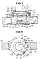
- FIG. 4 through 6 there is shown a rotary cutting tool according to a second embodiment of the invention.
- the rotary cutting tool comprises a cutter body 213 which is generally in the form of a cylinder.
- the cutter body 213 has its forward end which is formed, at its center, with a recess 214.
- the forward end of the cutter body 213 is enlarged in diameter.
- the cuter body 213 has its forward end whose outer periphery is formed with a plurality of grooves 215.
- the grooves 215 open toward the forward end face and the outer peripheral surface of the cutter body 213, and are formed in equidistantly spaced relation to each other in a peripheral direction of the cutting tool.
- a plurality of throw-away tips (hereinafter referred simply to as "tips") 216 are detachably mounted respectively to the grooves 215 by respective wedge elements 218 which are fastened by respective clamp screws 217.
- Each of the tips 216 is in the form of a plate and has its face 216a whose ridgelines are formed respectively into cutting edges 219.
- One of the cutting edges 219 slightly projects from the forward end face of the cutter body 213.
- a plurality of tip pockets 220 are formed in the cutter body 213 at respective locations where the outer peripheral surface of the cutter body 213 is directed toward the faces 216a of the respective tips 216.
- a work clamp mechanism 221 for pressing down a workpiece W2 is arranged at the forward end of the cutter body 213.
- a chip suction mechanism 222 is arranged radially outwardly of the peripheral surface of the cutter body 213 for drawing chips generated by the cutting edges 219 of the tips 216.
- a cutter fastening mechanism 223 is arranged at a location extending from the recess 214 of the cutter body 213 toward the proximal end thereof, for mounting the cutter body 213 to a main spindle of a machine body (not shown).
- the work clamp mechanism 221 is generally arranged such that a support element 224 generally in the form of a cylinder is inserted in the recess 214 of the cutter body 213, and a work clamp element 225 is connected to the support element 224.
- the support element 224 is arranged for movement axially of the cuter body 213.
- a groove 226 formed in the outer peripheral surface of the support element 224 is engaged with a forward end of a screw 227 which is screwed from the peripheral surface of the cutter body 213 to prevent the support element 224 from falling off from the recess 214.
- the support element 224 is always biased toward the forward end of the cutter body 213 by a plurality of springs 228 (refer to Fig. 5) which are arranged adjacent the proximal end of the cutter body 213 in equidistantly spaced relation to each other.
- a plurality of radial bearings 229 are fitted in the inner periphery of the support element 224, and have their respective outer rings which are fastened axially by a fastening nut 230.
- the radial bearings 229 have their respective inner rings which are fitted about a shaft section 225a formed adjacent the proximal end of the work clamp element 225, and which are axially fastened by a fastening nut 231.
- the work clamp element 225 is connected to the support element 224 through the radial bearings 229, and is rotatable about the rotational axis of the cutter body 213.
- the work clamp element 225 has its forward end which is formed into a disc shape.
- the disc-shaped forward end of the work clamp element 225 is formed, at its center, with a through bore 225b through which a connecting bolt 232 is inserted.
- the connecting bolt 232 forms a part of the cutter fastening mechanism 223.
- the work clamp element 225 has a forward end face 225c which is formed into an abutment surface with respect to the workpiece W2.
- the forward end face 225c is processed in finishing into a smooth surface, and has its peripheral edge section which is formed with a tapered section 225d.
- the forward end face 225c of the work clamp element 225 projects from the forward end face of the cutter body 213 under such a condition that the support element 224 biased by the springs 228 is located nearest the forward end of the cutter body 213.
- the biasing force of the springs 228 biasing the support element 224 is adjusted by their respective adjusting screws 228b.
- the chip suction mechanism 222 generally comprises a chip accommodating element or a cover assembly 233 generally in the form of a cylinder for covering an outer peripheral surface of the cutter body 213, a suction port element 234 provided in a peripheral wall of the cover assembly 233, and a plurality of chip guide elements 235 mounted to the peripheral edge of the forward end face of the cutter body 213.
- the cover assembly 233 has its proximal end formed with a fitting bore 233a.
- the fitting bore 233a is arranged adjacent the proximal end of the cutter body 213.
- the cover assembly 233 is connected to an adapter 236 through a radial bearing 237.
- the adapter 236 forms a part of the cutter fastening mechanism 223.
- the cover assembly 233 is rotatable relatively to the cutter body 213.
- the forward end of the cover assembly 233 extends to a location covering upper portions of the respective cutting edges 219 of the tips 216, which project radially outwardly of the cutter body 213.
- the forward end of the cover assembly 233 has its inner diameter which is so determined as to be slightly larger than a rotational locus of the cutting edges 219 about the axis of the cutter body 213.
- the cover assembly 233 has an intermediate section contiguous to its forward end, which is enlarged in diameter more than the forward end.
- the intermediate section has an inner peripheral surface which cooperates with an outer peripheral surface of the cutter body 213 adjacent the proximal end thereof, to define therebetween a chip accommodating chamber 238.
- the suction port element 234 is formed into a cylinder having its one end which is fitted in the intermediate section of the cover assembly 233.
- a suction hose 239 of a suction machine (not shown) is fitted about the outer periphery of the suction port element 234.
- the chip accommodating chamber 238 communicates with the suction machine through the suction hose 239.
- the cover assembly 233 is restricted by the suction hose 239 so that the cover assembly 233 is prevented from being rotated about its axis.
- each of the chip guide elements 235 is in the form of a planar plate, and is fixedly mounted to the cutter body 213 by a bolt 240 at a location which is directed toward the face 216a of the tip 216 at the peripheral edge of the forward end of the cutter body 213, to cover the tip pocket 220.
- each of the chip guide elements 235 is positioned axially such that its surface is substantially flush with the forward end face of the cutter body 213.
- the chip guide element 235 is positioned peripherally such that gap t2 occurs between the face 216a of the tip 216 and an end face 235a of the chip guide element 235, which is directed toward the face 216a.
- the chip guide elements 235 guide chips generated along the faces 216a from the cutting edges 219, into the respective tip pockets 220.
- a groove 235b is formed in a portion of each of the chip guide elements 235, which faces toward the tip pocket 220.
- the groove 235b extends from the end face 235a toward the wall surface of the tip pocket 220.
- the cutter fastening mechanism 223 comprises the adapter 236 whose forward end is fitted in the proximal end of the cutter body 213 and whose proximal end is connected to a main spindle of a machine body (not shown) through a tool holder (not shown), an intermediate element 241 inserted rotatably in the recess 214 of the cutter body 213, a drive key 243 fixedly mounted to the forward end of the adapter 236 and fitted in a key groove 242 provided in the rearward face of the intermediate element 241, and the connecting bolt 232 inserted in a central bore 241b in the intermediate element 241 and screwed into the center of the adapter 236.
- the intermediate element 241 is provided for restricting axial movement of the cutter body 213.
- a plurality of projections 244 are formed at the peripheral edge of the forward end of the intermediate element 241 in equidistantly spaced relation to each other in the peripheral direction of the cutting tool.
- the intermediate element 241 is firmly connected to the adapter 236 through the connecting bolt 232 under such a condition that the projections 244 are engaged respectively with smaller-diameter sections 245 which are formed at the recess 214 of the cutter body 213 in number corresponding to the projections 244. In this manner, the cutter body 213 is clamped between the intermediate element 241 and the adapter 236.
- the drive key 243 is fitted in one of a plurality of cut-outs 246 in the cutter body 213, which are formed in continuous to the smaller-diameter sections 245 thereof in a peripherally movable manner.
- the drive key 243 is engaged with one of a pair of opposed wall surfaces of one of the cut-outs 246 in the cutter body 213, which is located in front of the rotational direction (direction A in Fig. 5) under such a condition that the projections 244 of the intermediate section 241 are engaged respectively with the smaller-diameter sections 245 of the cutter body 213.
- the cutter body 213 is prevented from being rotated in a direction opposite to the cutter rotational direction.
- the proximal end of the adapter 236 is first connected to the main spindle of the machine body. Subsequently, the cut-outs 246 of the cutter body 213 are made in agreement respectively with the projections 244 of the intermediate element 241. The cutter body 213 is pressed down or pushed toward the adapter 236, and the proximal end of the cutter body 213 is fitted about the adapter 236. The cutter body 213 is rotated until the smaller-diameter sections 245 of the cutter body 213 are engaged respectively with the projections 244 of the intermediate element 241. Then, the connecting bolt 232 is tightened.
- the cutter body 213 is clamped between the adapter 236 and the intermediate element 241 so that the cutter body 213 is prevented from being moved axially. Further, the cutter body 213 is prevented from being rotated in a direction opposite to the cutter rotational direction (the direction A in Fig. 5) by the drive key 243 which is engaged with the wall surface of one of the cut-outs 246.
- the cutter body 213 After the cutter body 213 has been mounted to the main spindle, the cutter body 213 is rotated about its axis, and is fed in a direction perpendicular to the axis of the cutter body 213. Thus, the cutter body 213 cuts the workpiece W2 by the cutting edges 219 of the tips 216.
- the work clamp element 225 which projects from the forward end face of the cutter body 213, is gradually abutted against the cutting surface of the workpiece W2 from the tapered section 225b at the peripheral edge of the work clamp element 225, accompanied with feeding of the cutter body 213.
- the biasing load of the springs 228 biasing the support element 224 is transmitted to the work clamp element 225 through the support element 224, and serves as a force for pressing down the workpiece W2.
- the forward end of the cutter body 213 and the workpiece W2 are always maintained abutted against each other, so that fluctuation in the dynamic rigidity of the main-spindle system of the machine body is restricted.
- the biasing load of the springs 228 is beforehand adjusted by the respective adjusting screws 228a.
- the chips generated along the faces 216a of the respective tips 216 from the cutting edges 219 thereof at cutting are passed through the gaps t2 between the chip guide elements 235 and the faces 216a and are guided to the respective tip pockets 220.
- the chips are rounded off by each of the tip pockets 220 and are divided into pieces, and are discharged to the chip accommodating chamber 238.
- the chips discharged into the chip accommodating chamber 238 are drawn from the suction port element 234 by the suction machine through the suction hose 239 under the drawing action of the suction machine connected to the suction port element 234. In this manner, the chips are collected by the suction machine.
- the connecting bolt 232 of the cutter fastening mechanism 223 is loosened. Then, the cutter body 213 is rotated in the direction opposite to the direction A in Fig. 2 to disengage the projections 244 of the intermediate element 241 respectively from the smaller-diameter sections 245 of the cutter body 213. Subsequently, the cutter body 213 is removed from the interior of the cover assembly 233. The tips 216 are detached or demounted from the cutter body 213 and are replaced with new ones. Subsequently, the cutter body 213 is again engaged with the intermediate element 241, and is connected to the adapter 236.
- the dynamic rigidity of the main spindle system of the machine is considerably improved as compared with the case where the forward end of the cutter body 213 is released from the workpiece W2. Furthermore, there is no case where the value of the dynamic rigidity changes. Thus, occurrence of sheaves or shakes and vibration can considerably be restricted even in the case of so-called discontinuous or intermittent cutting in which a cutting force fluctuates due to discontinuous or intermittent contact between the tips 216 and the workpiece W2.
- the chips generated at cutting are successively drawn by the chip suction mechanism 222 without accumulation of the chips on the cutting surface of the workpiece W2. Accordingly, there occurs no case where the chips bite into a location between the workpiece W2 and the forward end face 225c of the work clamp element 225 to damage the cutting surface.
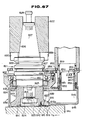
- FIG. 7 there is shown a rotary cutting tool according to a third embodiment of the invention.
- the rotary cutting tool comprises a cutter body 313 which is generally in the form of a cylinder.
- the cutter body 313 is formed, at its center, with a central bore 314 extending axially through the cutter body 313.
- the cutter body 313 has its forward end which is enlarged in diameter.
- the central bore 314 is fitted about a fitting shaft 318 of an arbor 317 which is mounted to a main spindle 315 of a machine body through a plurality of keys 316.
- the cutter body 313 is pressed down axially by a fastening bolt 320 which is screwed into the center of the arbor 317 under such a condition that a key groove 313a formed in the proximal end of the cutter body 313 is engaged with a drive key 319 fixedly mounted to the arbor 317. In this manner, the cutter body 313 is connected to the arbor 317.
- a plurality of grooves 321 are formed in the outer periphery of the forward end of the cutter body 313 in equidistantly spaced relation to one another.
- the grooves 321 open toward the forward end face and the outer peripheral surface of the cutter body 313.
- At least one, that is, a plurality of throw-way tips (hereinafter referred merely to as "tips") 322 are detachably mounted respectively to the grooves 321 by respective wedge elements 324 which are fastened respectively to the cutter body 313 by clamp screws 323.
- Each of the tips 322 has its face 322a whose ridgelines are formed respectively into cutting edges 325.
- One of the cutting edges 325 slightly projects from the forward end face of the cutter body 313.
- a plurality of tip pockets 326 each having an arcuate wall surface are formed in the cutter body 313 at respective locations which are directed respectively to the faces 322a of the respective tips 322.
- a chip accommodating element or a cover assembly 327 generally in the form of a cylinder is arranged at a location radially outwardly of the peripheral surface of the cutter body 313.
- the cover assembly 327 is formed, at its proximal end, with a fitting bore 327a which is fitted about a diameter-enlarged section 317a of the arbor 317, so that the cover assembly 327 is fitted about a radial bearing 329 which is retained by a ring-shaped retainer 328.
- the cover assembly 327 is connected, through a plurality of bolts 331, to a bearing retainer 330 at a location opposite to the ring-shaped retainer 328.
- the cover assembly 327 is supported rotatably with respect to the cutter body 313.
- the cover assembly 327 has its forward end which extends substantially to an intermediate location of the cutting edges 325 of the respective tips 322, which project radially outwardly of the cutter body 313.
- the cover assembly 327 has its inner diameter which is so determined as to be slightly larger than a rotational locus of the above-mentioned cutting edges 325 about the axis of the cutter body 313. Further, the cover assembly 327 has an intermediate section contiguous to its forward end, whose inner diameter is larger than that of the forward end.
- a chip accommodating chamber 332 is defined between an inner peripheral surface of the intermediate section of the cover assembly 327 and an outer peripheral surface of the proximal end of the cutter body 313, which is reduced in diameter radially inwardly of the cutter body 313.
- a pair of suction port elements 333 and 333 are arranged at the peripheral wall of the cover assembly 327.
- the suction port elements 333 and 333 are arranged at their respective locations where the outer peripheral surface of the cover assembly 327 is equally divided into two.
- the suction port elements 333 and 333 have their respective one ends which are fitted respectively in the intermediate section of the cover assembly 327.
- a pair of suction hoses 334 and 334 of a suction machine (not shown) are fitted respectively about the outer peripheries of the suction port elements 333 and 333.
- the chip accommodating chamber 332 communicates with the suction machine through the pair of suction hoses 334 and 334.
- the cover assembly 327 is restricted by the pair of suction hoses 334 and 334 so as to be prevented from being rotated about the rotational axis of the cover assembly 327.
- a chip guide element 335 is mounted to the forward end face of the cutter body 313 by a plurality of flat head screws 336 (only one shown).
- the chip guide element 335 comprises a thin ring-shaped mounting section 337 and a plurality of chip guide sections 338 formed at a peripheral edge of the mounting section 337 in equidistantly spaced relation to each other for covering respectively the tip pockets 326.
- the chip guide element 335 is axially positioned such that its surface is substantially in flush with the forward end face of the cutter body 313.
- the chip guide element 335 is positioned peripherally such that a gap t3 occurs between the face 322a of each of the tips 322 and an end face 338a of each of the chip guide sections 338, which is directed toward the face 322a of the tip 322. In this manner, the chip guide element 335 guides chips generated along the faces 322a of the respective tips 322, into the tip pockets 326 through the gaps t3.
- Each of the chip guide sections 338 has its forward end whose rearward face is formed with a groove 338b which extends from the end face 338a toward the wall surface of the tip pocket 326.
- the chips generated along the face 322a of each of the tips 322 from the cutting edges 325 thereof are passed through the gap t2 between the end face 338a of the chip guide element 335 and the face 322a of the tip 322, and are guided to the tip pocket 326.
- the chips are rounded off by the tip pocket 326 and are divided into pieces, and are discharged to the chip accommodating chamber 332.
- the chips discharged into the chip accommodating chamber 332 are drawn from the suction port elements 333 and 333 through the suction hoses 334 and 334 under the drawing action of the suction machine connected to the suction port elements 333 and 333 through the suction port elements 333 and 333. In this manner, the chips are collected by the suction machine.
- the chips generated at cutting are successively guided into the chip accommodating chamber 332 by the chip guide element 335.
- the chips are further drawn into the suction machine from the suction port elements 333 and 333 through the suction hoses 334 and 334, and are collected to the suction machine.
- the chips are not accumulated on the workpiece, a table of the machine body and the like, no deterioration in processing accuracy due to thermal deformation of the workpiece and the machine, nor deterioration in quality of the cut surface due to the biting of chips occurs. Furthermore, the chips do not enter the sliding surface of the machine body and the like so that the accuracy and the service life of the machine body is not reduced.
- the pair of suction port elements 333 and 333 are arranged respectively at their locations where the peripheral surface of the cover assembly 327 is equally divided into two. Accordingly, there can be provided such a functional advantage that the chip processing ability is improved as compared to a case where, particularly in a larger-diameter tool, the suction port element 333 is provided at a single location.
- the pair of suction port elements 333 and 333 are arranged at their respective locations where the cover assembly 327 is equally divided into two in the peripheral direction, the distance to the location most spaced apart from the vicinity of each of the suction port elements 333 and 333 can considerably be reduced. For this reason, a sufficient suction force acts even at a location most spaced apart from the suction port elements 333 and 333 of the chip accommodating chamber 332 so that the chips are always smoothly collected.
- the rotary cutting tool according to the invention should not be limited to this specific example. That is, the number of the suction port elements is selected in accordance with the tool diameter in an optimum manner. As a standard, two or three suction port elements 333 are sufficient within a range in which the diameter of the tool is less than 500 mm. In the case where the diameter of the tool is equal to or larger than 500 mm, it is preferable that at least four suction port elements are provided.
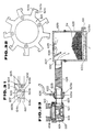
- the three suction port elements 333 are usually arranged in equidistantly spaced relation to each other along the rotational direction C of the cutter body 313.
- the feeding direction D of the cutter body 313 is particularly limited to one, only the tips 322 located in front of the feeding direction D cut the workpiece, while the tips 322 located to the rear of the feeding direction D do not participate in the cutting.
- the suction port elements 333 are arranged in front of the feeding direction D in a concentrated manner, a stronger suction force acts upon a range within which the chips are generated, so that the chip processing ability can further be improved.
- FIG. 12 there is shown a rotary cutting tool according to a fourth embodiment of the invention.
- the rotary cutting tool comprises a cutter body 413 which is generally in the form of a cylinder having a central bore 414.
- the cutter body 413 has its forward end whose outer periphery is formed with a plurality of recesses or grooves 415 in equidistantly spaced relation to each other in a peripheral direction of the cutting tool.
- a plurality of tips 416 each in the form of a planar plate are detachably mounted respectively to the grooves 415 under such a condition that a cutting edge 417 of each of the tips 416 projects from the forward end face and the outer peripheral surface of the cutter body 413.
- a plurality of tip pockets 420 are formed in the cutter body 413 at their respective locations directed toward faces 416a of the respective tips 416 which are arranged at the outer peripheral section of the forward end of the cutter body 413.
- the cutter body 413 is fastened axially by a fastening bolt 423 under such a condition that the central bore 414 in the cutter body 413 is fitted about a fitting shaft 422 of an arbor 421.
- the cutter body 413 is detachably connected to a main spindle 424 of a machine tool through the arbor 421.
- keys 425 and 426 are interposed respectively between the arbor 421 and the main spindle 424 and between the arbor 421 and the cutter body 413, for transmitting rotation of the main spindle 424 to the cutter body 413.
- a radial bearing (hereinafter referred simply to as "bearing") 428 is fitted about a support shaft 427 of the arbor 421, which is formed adjacent the proximal end of the fitting shaft 422.
- the bearing 428 is retained by a ring-shaped retainer 429.
- a cover assembly 430 is fitted about an outer ring of the bearing 428.
- the cover assembly 430 is connected, through a plurality of bolts 431a, to a bearing cap 431 which is fitted about the outer ring of the bearing 428 at a location opposite to the retainer 429.
- the cover assembly 430 is supported rotatably with respect to the cutter body 413.
- the cover assembly 430 comprises a generally cylindrical support cover 432 supported by the arbor 421 through the bearing 428, and a movable cover 433 which, similarly to the support cover 432, is generally in the form of a cylinder and which is fitted in an inner peripheral surface of the support cover 432 adjacent the forward end thereof.
- the forward end of the support cover 432 extends to a location adjacent the forward end of the cutter body 413, and substantially covers the outer peripheral surface of the cutter body 413. Further, the support cover 432 is formed with a plurality of elongated bores 432a at respective locations where the peripheral surface of the support cover 432 is equally divided into three. The elongated bores 432a extend axially of the cutter body 413. As shown in Figs. 12 through 14, the movable cover 433 is connected to the support cover 432 through a plurality of bolts 434 which are inserted respectively through the elongated bores 432a. Thus, the movable cover 433 is movable axially of the cutter body 413.
- a distance from the forward end of the movable cover 433 to the cutting edge 417 of each of the tips 416, which faces toward the forward end of the cutter body 413, is so set as to be larger than the maximum depth of cut of the cutting edge 417 facing radially outwardly of the outer periphery of the cutter body 413, under such a condition that the tip 416 approaches, to the maximum, the proximal end of the cutter body 413.
- the forward end of the movable cover 433 slightly projects from the forward end of the support cover 432 toward the forward end of the cutter body 413.
- a slight gap is left in a radial direction between the inner peripheral surface of the movable cover 433 and the cutting edge 417 of the tip 416, which is directed radially outwardly of the cutter body 413.
- a gap size is suitably set in accordance with material of the workpiece, cutting conditions and so on. It is preferable, however, that the gap size is within a range of from 0.5 mm to 2 mm. In order to do more reliable chip processing, it is desirable that the gap size is so set as to be within a range of from 0.5 mm to 1 mm.
- the gap quantity is less than 0.5 mm, there is a fear that the radially outward cutting edges 417 will bite into the movable cover 433 due to eccentricity of the cover assembly 430 or the like.
- the gap size exceeds 2 mm, there is a fear that chip suction force (subsequently to be described) becomes insufficient due to the amount of chips generated, the cutting conditions, and so on.
- a chip accommodating chamber 435 is defined between the inner peripheral surfaces of the respective covers 431 and 432 and the outer peripheral surface of the cutter body 413.
- the chip accommodating chamber 435 is partitioned from the side of the cover assembly 430 facing toward the bearing 428, by a diameter-reduced section 436 formed on the support cover 431 adjacent the proximal end thereof.
- the outer peripheral surface of the cover assembly 430 is formed with a through bore 437 which extends through the support cover 432 and the movable cover 433.
- a tubular suction port element 438 is fitted in the through bore 437.
- the suction port element 438 has its outer peripheral surface about which a suction hose 439 of a suction machine (not shown) is fitted.
- the chip accommodating chamber 435 communicates with the suction machine, and the cover assembly 430 is restricted by the suction hose 439 and is prevented from being rotated thereby.
- a chip guide element 440 is embedded in the forward end face of the cutter body 413 such that a forward end face of the chip guide element 440 is substantially flush with the forward end face of the cutter body 413.
- the chip guide element 440 is fixedly mounted to the cutter body 413 by a plurality of flat head screws 441 (only one shown).
- the chip guide element 440 comprises a thin ring-shaped mounting section 442, and a plurality of guide sections 443 formed at a peripheral edge of the mounting section 442 in equidistantly spaced relation to each other.
- the guide sections 443 extend radially outwardly of the cutter body 413.
- the guide sections 443 have their outer diameter which is so determined as to be the same as the outer diameter of the cutter body 413.
- each of the guide sections 443 has its forward end which is formed with a projection 444 which is fitted in a corresponding one of the tip pockets 420.
- a gap t4 is defined between the face 416a of the tip 416 and an end face 444a of the projection 444 facing toward the face 416a, for guiding chips generated along the face 416a, into the tip pocket 420.
- the projection 444 is formed with a groove 444c which opens toward the end face 444a and an upper face 444b of the projection 444.
- a distance from the upper surface 444b of the projection 444 to the cutting edge 417 of the tip 416 facing toward the forward end of the cutter body 413 is so determined as to be slightly larger than the maximum depth of cut of the cutting edge 417 which faces radially outwardly of the cutter body 413.
- the position of the movable cover 433 is adjusted such that the cutting edge 417 facing radially outwardly of the cutter body 413 is exposed from the forward end of the movable cover 433 by a quantity slightly longer than the predetermined depth of cut.
- the cutter body 413 is mounted to the main spindle 424 through the arbor 421.
- the cutter body 413 is rotated about its rotational axis while air within the chip accommodating chamber 435 is drawn by the suction machine connected to the suction port element 438.
- the cutter body 413 is also fed in a direction perpendicular to the rotational axis. Accompanied with the rotation and feeding, the cutting edges 417 projecting from the forward end face and the outer peripheral surface of the cutter body 413 cut the workpiece.
- the movable cover 433 is axially positioned such that the forward end of the movable cover 433 is positioned at a location slightly closer to the proximal end of the cutter body 413 than the depth of cut of the cutting edge 417 which faces radially outwardly of the cutter body 413.
- the chips generated along the face 416a of the tip 416 from the cutting edge 417 thereof are strongly drawn toward the chip accommodating chamber 435 while being guided to the gap t4 between the end face 444a of the chip guide element 440 and the face 416a of the tip 416.
- the chips are rounded off and divided into pieces by the tip pocket 420, and are guided to the chip accommodating chamber 435.
- the chips are further drawn and collected to the suction machine from the chip accommodating chamber 435 through the suction hose 439.
- the projecting amount or quantity of the movable cover 433 should change in accordance with the alteration of the depth of cut, to adjust the exposure quantity of the cutting edges 417.
- the face milling cutter of the fourth embodiment there are provided the following functional advantages. That is, since the chips generated at cutting are successively drawn and collected without scattering to the circumference of the machine, the working or operating environment can be considerably improved, and the period of time required for the chip processing can be considerably reduced. Moreover, since the chips are not accumulated on the workpiece, the table of the machine tool and the like, no deterioration in processing accuracy due to thermal deformation of the workpiece and the machine nor deterioration in quality of the cut surface accompanied with biting of the chips occurs. Furthermore, the chips do not enter the sliding surface of the machine tool and the like so that it can be prevented to reduce the accuracy and the service life of the machine tool.
- the movable cover 433 is provided for movement axially of the cutter body 413. Accordingly, even if the depth of cut of the cutting edges 417 changes, the position of the movable cover 433 is adjusted in accordance with the change in the depth of cut of the cutting edges 417, thereby enabling the maximum suction force to be always applied to the circumference of the cutting edges 417. As a result, there is obtained such a functional advantage that chip processing can be done more reliably.
- the movable cover 433 is slidably inserted in the inner peripheral surface of the support cover 432, and the movable cover 433 and the support cover 432 are connected to each other by the bolts 434 which extend respectively through the elongated bores 432a, thereby enabling the forward end of the cover assembly 430 to be adjusted in position.
- the fourth embodiment should not be limited to this specific example. A pair of modifications of the fourth embodiment will be described with reference to Figs. 18 and 19. In this connection, in Figs. 18 and 19, components and parts like or similar to those illustrated in Figs. 12 through 17 are designated by the same reference numerals, and the description of the like or similar components and parts will be omitted to avoid repetition.
- a cover assembly 450 comprises a support ring 451 rotatably mounted to the outer peripheral surface of the arbor 421 through the bearing 428, and a movable cover 452 fitted about the outer periphery of the support ring 451 to cover the cutter body 413.
- the movable cover 452 opens toward the forward end of the cutter body 413.
- the movable cover 452 is connected to the support ring 451 through a plurality of bolts 453 which extend respectively through the elongated bores 452a formed in the peripheral surface of the movable cover 452.
- the movable cover 452 has its forward end which is adjustable in position axially of the cover body 413.
- the movable cover 452 has its peripheral wall which is formed with a through bore 454 in which the suction port element 438 is fitted.
- the position of the forward end of the movable cover 452 is adjusted in accordance with the depth of cut of the cutting edges 417, whereby there can be obtained functional advantages which are similar to those obtained by the fourth embodiment.
- the movable cover 452 is exposed to the outside of the support ring 451, there is also obtained such a functional advantage that the axial position of the movable cover 452 can be adjusted extremely easily.
- a cover assembly 460 comprises a support cover 461 covering the peripheral surface of the cutter body 413 and opening toward the forward end of the cutter body 413, and a movable ring 462 arranged on the inner peripheral surface of the forward end of the support cover 461.
- the movable ring 462 is in the form of a short cylinder.
- the support cover 461 is rotatably supported by the arbor 421 through the bearing 428.
- the suction port element 438 is fitted in a through bore 463 which is formed in the peripheral wall of the support cover 461.
- the movable ring 462 has its outer peripheral surface which is formed with a male threaded section 462a.
- the male threaded section 462a is threadedly engaged with a female threaded section 461a formed in the inner peripheral surface of the forward end of the support cover 461, whereby the movable ring 462 is united together with the support cover 461.
- FIG. 20 there is shown a rotatable cutting tool according to a fifth embodiment of the invention.
- the rotatable cutting tool comprises a cutter body 520 which is generally in the form of a cylinder having a central bore 521.
- a plurality of recesses or grooves 522 are formed in an outer periphery of a forward end of the cutter body 520 in equidistantly spaced relation to each other.
- the grooves 522 open toward the forward end and the outer periphery of the cutter body 520.
- a plurality of tips 523 each in the form of a planar plate are detachably mounted respectively to the grooves 522 by respective clamp elements 526 fastened respectively by clamp screws 525, under such a condition that cutting edges 524 of the respective tips 523 project from the forward end face and the outer peripheral surface of the cutter body 520.
- each of the clamp elements 526 comprises a wedge section 527 inserted into a location between the wall surface of a corresponding one of the grooves 522 and a face 523a of the tip 523 to press down the tip 523 in a peripheral direction of the rotatable cutting tool, and a chip guide section 528 which projects from the forward end of the wedge section 527 toward the outer periphery of the cutting tool radially thereof.
- the wedge section 527 has a wall surface 527a which is formed into a curved surface.
- the curved wall surface 527a is arcuately concave toward the inner peripheral side of the cutting tool from the outer peripheral surface of the forward end of the cutter body 520.
- a space occurring between the wall surface 527a and the outer peripheral surface of the forward end of the cutter body 520 serves as a tip pocket which rounds off chips generated by the cutting edge 524.
- the wedge section 527 has its forward end face which is formed substantially flush with the forward end face of the cutter body 520.
- the chip guide section 528 is formed as follows. Specifically, an end face 528a of the chip guide section 528 on the side of its outer periphery extends to a location moved slightly rearwardly toward the inner periphery of the cutting tool from the cutting edge 524 of the tip 523, which faces radially outwardly of the cutting tool, to substantially close the groove 522 at the forward end of the cutting tool.
- a recession quantity ⁇ 1 of the radially outward end face 528a of the chip guide section 528 with respect to the cutting edge 524 is suitably determined in accordance with material of the workpiece, cutting conditions and so on. It is preferable, however, that the recession quantity is set to a range of from 0.2 mm to 1.0 mm. If the recession quantity ⁇ 1 is less than 0.2 mm, the chip guide section 528 will bite into the workpiece due to an error in mounting of the tip 523 or the like. On the other hand, if the recession quantity ⁇ 1 exceeds 1.0 mm, the gap becomes excessive between the end face 528a and an inner peripheral surface of a forward end of a cover assembly subsequently to be described. In this case, a chip suction force subsequently to be described becomes insufficient so that there is a fear that the insufficient chip suction force interferes with chip processing.
- a cut-out 529 is formed in the end face of the chip guide section 528, which is directed toward the face 523a of the tip 523.
- the cut-out 529 permits passage of the chips which are generated along the face 523a.
- a gap size t5 between the cut-out 529 and the face 523a is suitably determined in accordance with the material of the workpiece, the cutting conditions and so on. It is preferable, however, that the gap size t5 is set to a range of from 0.2 mm to 1 mm. If the gap size t5 is less than 0.2 mm, the chips are clogged in the gap t5 so that there occurs such a fear that the chip processing is stagnated. On the other hand, if the gap size t5 exceeds 1mm, a chip suction force becomes insufficient so that there is such a fear that the insufficient gap size t5 interferes with chip processing.
- a plurality of grooves 530 are formed respectively in the chip guide sections 528, and open respectively toward the grooves 522.
- Each of the grooves 530 opens toward the cut-out 529 and enlarges the gap t5 between the cut-out 529 and the face 523a at the side facing toward the groove 522 to prevent the chips passing through the cut-out 529 from being clogged.
- the cutter body 520 is axially tightened by a fastening bolt 534 and is united together with an arbor 532 under such a condition that the central bore 521 in the cutter body 520 is fitted about a fitting shaft 533 of the arbor 532.
- the arbor 532 is provided for connecting the cutter body 520 to a main spindle 535 of a machine body. Rotation of the main spindle 535 can be transmitted to the cutter body 520 by a key 537 interposed between the cutter body 520 and the arbor 532 and by a plurality of keys 538 interposed between the main spindle 535 and the arbor 532.
- a cover assembly 540 is rotatably mounted to a support shaft 539 formed at the fitting shaft 533 of the arbor 532, through a radial bearing (hereinafter referred simply to as "bearing") 541.
- the cover assembly 540 is formed generally into a cylinder which opens toward the forward end of the cutting tool.
- the cover assembly 540 has its forward end which extends to a location overlapping with the chip guide section 528 of each of the clamp elements 526 in an axial direction of the cutting tool.
- the forward end of the cover assembly 540 has its inner diameter which is so determined as to be slightly larger than a rotational locus of the cutting edges 524.
- a gap size ⁇ 2 between the inner peripheral surface of the forward end of the cover assembly 540 and the cutting edges 524 of the tips 523 in the radial direction of the cutting tool is suitably determined in accordance with material of the workpiece, cutting conditions, and so on. It is desirable, however, that the gap size ⁇ 2 is set to a range of from 0.5 mm to 2 mm. In order to perform more reliable chip processing, it is desirable that the gap size ⁇ 2 is set to a range of from 0.5 mm to 1 mm. If the gap size ⁇ 2 is less than 0.5 mm, there is a fear that the cutting edge 524 bites into the cover assembly 540 due to eccentricity of the cover assembly 540 or the like. On the other hand, if the gap size ⁇ 2 exceeds 2 mm, there occurs a fear that a chip suction force subsequently to be described becomes insufficient due to an amount or quantity of the chips generated, the cutting conditions, and so on.
- a chip accommodating chamber 542 is defined between the inner peripheral surface of the cover assembly 540 and the outer peripheral surface of the cutter body 520.
- the chip accommodating chamber 542 is partitioned from the side of the cover assembly 540 facing toward the bearing 541 by a diameter-reduced section 543 formed on the cover assembly 540 on the side of the proximal end thereof.
- a through bore 544 is formed in the peripheral wall of the cover assembly 540.
- a suction port element 545 is fitted in the through bore 544.
- a suction hose 546 of a suction machine (not shown) is fitted about an outer periphery of the suction port element 545.
- the chip accommodating chamber 542 communicates with the suction machine.
- the cover assembly 540 is restricted by the suction hose 546 so as to be prevented from being rotated from the axis of the cover assembly 540.
- the chips generated along the face 523a of each of the tips 523 from the cutting edges 524 thereof are strongly drawn toward the chip accommodating chamber 542 while being guided through the gap between the cut out 529 of the chip guide section 528 and the face 523a of the tip 523.
- the chips are rounded off and divided into pieces by the wall surface 527a of the clamp element 526, and are guided into the chip accommodating chamber 542.
- the chips are further drawn from the chip accommodating chamber 542 through the suction hose 546 and are collected to the suction machine.
- the chip guide sections 528 are provided respectively at the clamp elements 526, it is not required to remodel the forward end of the cutter body 520 in order to cover the grooves 522. Further, since the cover assembly 540 and the suction port element 545 are mounted to the arbor 532, it is not also required to remodel the cutter body 520 in order to cover the peripheral surface of the cutter body 520. Thus, there can be obtained a superior functional advantage that the cutter body used conventionally is easily diverted to perform chip processing.
- the chip guide sections 528 are particularly formed in an integral manner respectively with the clamp elements 526.
- the invention should not be limited to this specific example.
- the arrangement may be such that the wedge section 527 is formed separately from the chip guide section 528, and the wedge section 527 and the chip guide section 528 are connected to each other through a bolt 549.
- the gap quantity t5 between the cut-out 529 and the face 523a of the tip 523 can easily be adjusted in accordance with the configuration of the chips generated, and the wedge section 527 and the chip guide section 528 can easily be replaced with new ones at breakage thereof.
- the clamp element 526 is particularly pressed or urged against the tip 523 by the wedge effect.
- the invention should not be limited to this specific example. Various modifications can be made to the invention. That is, the arrangement may be such that the tip 523 is directly fastened in its thickness direction.
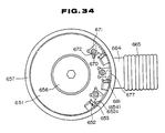
- FIG. 29 through 33 there is shown a rotatable cutting tool according to a sixth embodiment of the invention.
- the rotatable cutting tool comprises a cutter body 601.
- the cuter body 601 is cylindrical in shape and has its forward end which extends forwardly more than the conventional face milling cutter described previously with reference to Figs. 76 through 78.
- a plurality of tip mounting grooves 602 and a plurality of tip pockets 607 are formed in the outer periphery of the forward end of the cutter body 602 in equidistantly spaced relation to each other in a peripheral direction of the cutting tool, similarly to the conventional face milling cutter shown in Figs. 76 through 78.
- Each of the clamp mechanisms 606 comprises a wedge element 604 and a clamp screw 605.
- a chip guide element 614 is embedded in the forward end face of the cutter body 601 such that a surface of the chip guide element 614 is moved slightly rearwardly in the axial direction of the cutting tool with respect to the face cutting edge 603a.
- the chip guide element 614 is provided for guiding and discharging chips generated by the cutting edges 603a and 603b to a chip accommodating space or a chip discharge space 621 subsequently to be described.
- the chip guide element 614 is fixedly mounted to the cutter body 601 by a plurality of flat head screws 615 (only one shown).
- the chip guide element 614 is in the form of a plate which is formed, at its outer periphery, with a plurality of hook-shaped sections 614a in equidistantly spaced relation to each other in the peripheral direction of the cutting tool.
- the hook-shaped sections 614a are the same in number as the tips 603.
- the chip guide element 614 has its outer diameter which is so determined as to be slightly smaller than a rotational locus of the outer peripheral cutting edges 603b.
- each of the hook-shaped sections 614a has their outer peripheral surface which is located at a position slightly moved rearwardly toward the radial inner side of the cutter body 601 from the outer peripheral cutting edges 603b of the respective tips 603. Further, each of the hook-shaped sections 614a is determined in configuration as follows. That is, when the chip guide element 614 is fixedly mounted to the cutter body 601, as shown in Figs. 30 and 31, each of the hook-shaped sections 614a covers a corresponding one of the tip pockets 607 to close the chip discharge space 621 subsequently to be described.
- a slight gap occurs between a forward end face 614b of each of the hook-shaped sections 614a in the bending direction and the face of the corresponding tip 603, so that chips torn off from the surface of the workpiece by the cutting edges 603a and 603b are guided to the tip pocket 607.
- a groove 614c is formed in the forward end portion of the hook-shaped section 614a, and opens in the bending direction of the hook-shaped section 614a and toward the mounting face of the chip guide element 614.
- the gap portion between the face of the tip 603 and the forward end face 614b of the hook-shaped section 614a in the bending direction is enlarged inwardly to prevent the chips passing through the gap portion from being clogged.
- a mounting bore 610 of the cutter body 601 is fitted about a shaft section 608a of an arbor 608, and a fastening bolt 611 is screwed into the end face of the shaft section 608a of the arbor 608 from the end face of the cutter body 601 on the larger diameter side thereof, whereby the cutter body 601 is fixedly mounted in unison to the arbor 608 through a detent key 609 in a coaxial or eccentric manner.
- a taper shank 608b is provided on the arbor 608 at a location opposite to the shaft section 608a, and is fitted in the tapered bore 612a in a main spindle 612.
- a female threaded section is formed at the forward end of the taper shank 608b for firmly connecting the face milling cutter tool and the main spindle 612 to each other by a drawing bolt (not shown)
- a larger-diameter shaft section 608c is formed at the rearward end of the shaft section 608a of the arbor 608.
- a bearing 617 is fixedly mounted to the largerdiameter shaft section 608c by a retainer ring 616.
- a chip accommodating element or a cover assembly 618 is fitted about an outer ring of the bearing 617.
- the cover assembly 618 is connected in unison to a cover 619 fitted about the outer ring of the bearing 617 from the side opposite to the retainer ring 616, through a plurality of bolts 620 (only one shown) so that the cover assembly 618 is rotatable coaxially with respect to the cutter body 601.
- the cover assembly 618 is in the form a thin hollow cylinder for covering the cutter body 601 and the outer peripheral cutting edges 603b of the tips 603.
- the cover assembly 618 has its inner diameter which is so determined as to form the chip discharge space 621 between the inner peripheral surface of the cutter body 601 and the outer peripheral surface of the smaller-diameter section of the cutter body 601.
- the chip discharge space 621 has its dimension sufficient to accommodate the chips divided into pieces by the tip pockets 607.
- the inner peripheral surface of the cover assembly 618 adjacent the bearing 617 is narrowed to such a degree as to be slightly larger than the smaller-diameter section of the cutter body 601.
- the forward end face of the cover assembly 618 is positioned at a location which is slightly moved rearwardly axially from a portion of each of the outer peripheral cutting edges 603b of the tips 603, which is bitten into the workpiece.
- the forward end of the cover assembly 618 has its inner peripheral surface which is narrowed to such a degree as to be slightly larger than a rotational locus of the outer peripheral cutting edges 603b of the tip 603.
- an air jet pump 622 is connected to the outer peripheral surface of the cover assembly 618, for drawing the chips within the chip discharge space 621 together with air to discharge the chips to the outside. That is, a connecting pipe 623 is fitted in a through bore 618a formed in the peripheral wall of the cover assembly 618.
- the air jet pump 622 has its suction port section which is connected to a flange 623a of the connecting pipe 623.
- a duct hose 624 has its one end which is fitted about and connected to a discharge port section of the air jet pump 622.
- the air jet pump 622 has a body 625 which is formed into a cylindrical shape and whose proximal end is formed into the suction port section.
- the air jet pump 622 is connected to the flange 623a of the connecting pipe 623.
- the air jet pump 622 has its other end which is formed into the discharge port section connected to one end of the duct hose 624.
- the body 625 has its peripheral wall which is formed with an air chamber 625a.
- the air chamber 625a is annular in shape and extends around the peripheral wall of the body 625 in the peripheral direction.
- a tapered air jetting passage 625b is formed which extends from the position of the proximal end of the air chamber 625a toward the forward end of the inner peripheral surface of the body 625.
- the body 625 has its inner peripheral surface which is most reduced in diameter at a location adjacent the opening section of the air jetting passage 625b.
- the inner peripheral surface of the body 625 is gradually enlarged in diameter from the opening seotion of the air jetting passage 625b toward the proximal end and the forward end of the body 625.
- an air supply hose 626 is connected to the air chamber 625a and is connected to an air supply source.
- the duct hose 624 has its other end which is connected to a chip receiving box 627 as shown in Fig. 33.
- the chip receiving box 627 is so constructed that a side wall of the chip receiving box 627 is capable of being divided into upper and lower sections.
- the lower section of the chip receiving box 627 is formed into a chip accommodating section 628, and the upper portion is formed into a lid or closure 629.
- a mesh receiving plate 630 is provided at a location adjacent a bottom face 628a of the chip accommodating section 628, for receiving chips S6.
- a discharge pipe 631 is provided at the side wall of the chip accommodating section 628 at a location adjacent the mesh receiving plate 630, for discharging cutting oil F .
- a pipe 632 is provided at the side wall of the closure 629, for causing the duct hose 624 to communicate with the interior of the chip receiving box 627.
- An air-discharge filter 633 is provided at a ceiling wall of the closure 629.
- a shielding plate 634 is provided in an inclined manner in a direction directed downwardly away from the opening of the pipe 632, for shielding a portion on an extension line of the opening of the pipe 632.
- the chips torn off from the surface of the workpiece by the face cutting edges 603a are guided to the gap sections between the faces of the tips 603 and the end faces of the hook-shaped sections 614a of the chip guide element 614 from the surface side thereof, and are discharged and divided into pieces into the tip pockets 607. Further, the chips torn off from the surface of the workpiece by the outer peripheral cutting edges 603b are guided to the gap sections between the faces of the tips 603 and the end faces of the hook-shaped sections 614a of the chip guide element 614 from the outer peripheral surface side thereof, and are discharged and divided into pieces into the tip pockets 607.
- the divided chips are pushed up into the chip discharge space 621.
- the new chips are passed from the through bore 618a through the air jet pump 622 and the duct hose 624, and are collected in the chip receiving box 627.
- the air jet pump 622 the air is jetted at a high speed toward the forward end of the body 625 through the air jetting passage 625b. Since the jetting section of the air is reduced in diameter, the pressure at the jetting section is rendered negative. Further, since the air at the proximal end of the body 625 is pulled due to the inertia force of the jetting air, sufficient air within the chip discharge space 621 is drawn by the air jet pump 622.
- the chips S6 fed into the chip receiving box 627 is abutted against the shielding plate 634 so that the chips S6 are rapidly reduced in speed and are accumulated on the mesh receiving plate 630. Further, the cutting oil F adhering to the chips S6 falls down through the mesh receiving plate 630 and accumulates at the bottom surface 628a of the chip receiving box 627. The oil F is discharged through the discharge pipe 631. The air is discharged through the filter 633.
- the chips generated at cutting by the cutting edges 603a and 603b are passed into the tip pockets 607 by the chip guide elements 614, and are guided to the chip discharge space 621.
- the chips are successively drawn and discharged to the outside of the cover assembly 6I8 by the air jet pump 622.
- the chips are prevented from being accumulated on the surface of the workpiece, and from being scattered onto the machine and to the vicinity thereof.
- the air jet pump 622 since the air is drawn by the air jet pump 622, there is obtained also such a functional advantage that sufficient air within the chip discharge space 621 can be drawn. Since, in the air jet pump 622, mere supply of the air through the air supply hose 626 enables the suction force to be exhibited, there is also such a functional advantage that the air jet pump 622 can be installed simply and at low cost. Further, since the air jet pump 622 has no rotating mechanisms, no accident occurs due to biting of the chips or the like, and maintenance is also simple.
- the chip receiving box 627 is provided with the shielding plate 627, falling chips S6 are separated from the air in a short period of time, so that only air is discharged through the filter 633. Further, there is also such a functional advantage that it is possible to separate the chips S6 from the cutting oil F by the mesh receiving plate 630.
- FIG. 34 through 39 there is shown a rotatable cutting tool according to a seventh embodiment of the invention.
- a face milling cutter in the seventh embodiment is common to the face milling cutters in the previous first through sixth embodiments in the following points. That is, a plurality of cutting tips 652 are mounted to an outer periphery of a forward end of a cutter body 651.
- a cover assembly 657 is rotatably mounted, through a bearing 658, to an arbor 655 connected to a proximal end of the cutter body 651.
- a discharge or suction port element 664 is provided at the outer periphery of the cover assembly 657. The suction port element 664 communicates with a chip accommodating chamber 659.
- the seventh embodiment differs from the previous embodiments in the following points. That is, a plurality of mounting seats 670 are formed at respective locations which are directed toward the cutting tips 652 at the forward end face of the cutter body 651. A plurality of chip guide elements 671 are detachably mounted respectively to the mounting seats 670 by respective bolts 672. The configuration of the chip guide elements 671 per se is also different from that of each of the previously described embodiments.
- each of the chip guide elements 671 comprises a mounting section 673 fitted in a corresponding one of the mounting seats 670 of the cutter body 651, and a chip guide section 675 for covering the opening of a corresponding one of the tip pockets 674 of the cutter body 651 at the forward end thereof.
- the mounting section 673 is formed into a generally square planar plate.
- the mounting section 673 has its center which is formed with a bolt bore 676 through which the bolt 672 extends or is passed.
- the chip guide section 675 is formed into a planar plate which is longer than the mounting section 673 in the tool peripheral direction.
- the chip guide section 675 has an outer peripheral side face 677 which is formed into an arcuate shape.
- the arcuate outer peripheral side surface 677 has its curvature which is the same as that of the outer peripheral surface of the cover body 651.
- a groove 679 is formed in a surface 678 of the chip guide section 675, which faces toward the chip accommodating chamber 659.
- the groove 679 has its one end which opens to an end face 680 directed toward a face 652a of the cutting tip 652.
- a wall surface 681 of the groove 679 facing toward the outer peripheral side surface 677 is formed into a concave face which is arcuate substantially in coaxial relation to the outer peripheral side surface 677.
- a wall surface 682 of the groove 679 adjacent the mounting section 673 is formed into a surface which is concave arcuately toward the mounting section 673.
- the wall surface 682 has its dimension which is substantially the same in curvature as a wall surface 683 of the tip pocket 674 in the cutter body 651.
- These wall surfaces 681 and 682 are smoothly connected to each other through an arcuate surface 684.
- the groove 679 has a bottom surface 685 which is formed into a planar surface extending in parallel relation to the other surface 686 of the chip guide element 671.
- the end face 680 of the chip guide section 675 is formed into an inclined surface which is inclined a predetermined angle with respect to the surface 678.
- An inclined angle ⁇ 7 of the inclined surface is so determined as to be equal to an axial rake angle ⁇ 7 given to the face 652a of the cutting tip 652 mounted to the cutter body 651.
- the mounting section 673 described above is fitted in the mounting seat 670 of the cutter body 651, whereby the chip guide element 671 constructed as above is mounted in position on the forward end face of the cutter body 651.
- the chip guide element 671 is fastened by the bolt 672 and is fixedly mounted to the cutter body 651.
- the outer peripheral side surface 677 of the chip guide section 675 is contiguous to the outer peripheral surface of the cutter body 651, and is so positioned as to describe an arc identical with the outer peripheral surface of the cutter body 651.
- the end face 680 of the chip guide section 675 is so positioned as to form a constant gap t7 between the end face 680 and the face 652a of the cutting tip 652.
- the relationship between the depth of the mounting seat 670 and the wall thickness of the chip guide element 671 is so determined that the surface 686 facing toward the forward end of the cutting tool is moved rearwardly toward the proximal end of the cutting tool from the cutting edge 654 of the cutting tip 652, and the surface 678 of the chip guide element 671 facing toward the chip accommodating chamber 659 is moved rearwardly toward the proximal end of the cutting tool from the forward end of the cover assembly 657.
- a suction hose 665 is connected to the discharge port element 664 connected to the cover assembly 657 to draw air within the chip accommodating chamber 659, whereby the chips generated by the cutting edges 653 and 654 are successively drawn and collected through the gap t7 between the end face 680 of the chip guide element 671 and the face 652a of the cutting tip 652.
- the outer peripheral side surface 677 of the chip guide element 671 is contiguous to the outer peripheral surface of the cutter body 651 and is formed into the arcuate surface describing the arc identical with the outer peripheral surface of the cutter body 651.
- the wall surface 681 of the groove 679, which faces toward the outer peripheral side surface 677, is also formed into the arcuate surface which is substantially coaxial with the outer peripheral side surface 677.
- the wall thickness between the outer peripheral side surface 677 and the groove wall surface 681 is thinned till a range of minimum strength-retention, whereby it is possible to considerably enlarge the groove 679 radially outwardly of the cutting tool more than that of each of the previous embodiments, while the outer peripheral side surface 677 is stored within the rotational locus of the cutting tip 653.
- discharge of the chips within the grooves 679 is improved so that clogging of the chips at the gaps t7 between the end faces 680 of the chip guide elements 671 and the faces 652a of the cutting tips 652 is beforehand avoided, thereby enabling the suction and collection of the chips to be done more reliably.
- the seventh embodiment has been described in which the wedge elements for fixedly mounting the cutting tips and the chip guide elements are particularly provided separately from each other.
- a rotatable cutting tool in which a wedge element 690 is arranged on the side of the face 652a of each of the cutting tips 652, it is possible to divert the wedge element 690 to bring the same into a chip guide element.
- a chip guide section 691 is formed on the one end of the wedge element 690 in an integral manner.
- An outer peripheral side surface 692 of the chip guide section 691 is formed into an arcuate surface contiguous to the outer peripheral surface of the cutter body 651.
- a groove 693 is formed in the chip guide section 691 at a location which is directed toward the chip accommodating chamber 659.
- a wall surface 694 of the groove 693 facing toward the outer peripheral side surface 692 is formed into an arcuate surface which is substantially coaxial with the outer peripheral side surface 692.
- the reference numeral 695 in Figs. 40 through 45 denotes an end face which is directed toward the face 652a of the cutting tip 652.
- the end face 695 is formed into an inclined surface which is inclined at the same angle as the axial rake angle of the face 652a.
- an outer peripheral side surface 696 of the wedge element 690 is formed into an arcuate surface which is contiguous to the wall surface 683 of the tip pocket 674 of the cutter body 651.
- a bolt 697 for mounting the wedge element 690 to the cutter body 651 is inserted through a bolt bore 698.
- FIG. 46 through 51 there is shown a rotatable cutting tool according to an eighth embodiment of the invention.
- a face milling cutter in the eighth embodiment is common to the face milling cutters in the previous embodiments in the following points. That is, a plurality of cutting tips 702 are mounted to an outer periphery of a forward end of a cutter body 701. A cover assembly 707 is rotatably mounted, through a bearing 708, to an arbor 705 connected to a proximal end of the cutter body 701. A discharge or suction port element 714 is provided at the peripheral surface of the cover assembly 707. The suction port element 714 communicates with a chip accommodating chamber 709.
- the eighth embodiment differs from the previous first through sixth embodiments in the following points. That is, a plurality of mounting seats 720 are formed at respective locations which are directed toward the cutting tips 702 at the forward end face of the cutter body 701. A plurality of chip guide elements 721 are detachably mounted respectively to the mounting seats 720 by respective bolts 722. The configuration of the chip guide elements 721 is also different from that of each of the previously described first through seven embodiments.
- each of the chip guide elements 721 comprises a mounting section 723 fitted in the mounting seat 720 of the cutter body 701, and a chip guide section 725 for covering the opening of a tip pocket 724 in the cutter body 701 at the forward end thereof.
- the mounting section 723 is formed into a generally square planar plate.
- the mounting section 723 has its center which is formed with a bolt bore 726 through which the bolt 722 extends or is passed.
- the bolt bore 726 comprises a bolt seat 726a engaged with the head of the bolt 722, and a through bore 726b through which the threaded section of the bolt 722 extends.
- the bolt bore 726 is formed into an elongated configuration extending generally in the peripheral direction of the cutter body 701. Further, a width dimension W8 of the mounting section 723 in the peripheral direction of the cutter body 701 is so determined as to be smaller than a width W28 of the mounting seat 720 of the cutter body 701.
- the chip guide section 725 is formed into a planar plate which is longer than the mounting section 723 in the tool peripheral direction.
- a groove 728 is formed on a surface 727 of the chip guide section 725, which faces toward the chip accommodating chamber 709.
- the groove 728 has its one end which opens to an end face 729 which is directed toward a face 702a of the cutting tip 702.
- the groove 728 has its one wall surface 730 which is formed into a planar surface extending generally in parallel relation to an outer peripheral side surface 731 of the chip guide section 725.
- the other wall surface 732 is formed into an arcuate concave surface which is depressed toward the mounting section 723.
- the other wall surface 732 has its curvature which is substantially the same as that of a wall surface 733 (refer to Fig. 48) of the tip pocket 724 of the cutter body 701.
- These wall surfaces 730 and 732 are smoothly connected to each other through an arcuate surface 734.
- the groove 728 has its bottom surface 735 which is formed into a planar surface extending generally in parallel to the other surface 736 of the chip guide element 721.
- the end face 729 of the chip guide section 725 is formed into an inclined surface which is inclined a predetermined angle with respect to the surface 727.
- An inclined angle ⁇ 8 of the inclined surface is so determined as to be equal to an axial rake angle ⁇ 8 given to the face 702a of the cutting tip 702 mounted to the cutter body 701.
- the mounting section 723 described above is fitted in the mounting seat 720 of the cutter body 701, whereby the chip guide element 721 constructed as above is mounted in position on the forward end face of the cutter body 701. Further, the chip guide element 721 is fastened to the cutter body 701 by the bolt 722 and is fixedly mounted to the cutter body 701. At this time, the outer peripheral side surface 731 of the chip guide section 725 is so positioned as not to protrude from the outer peripheral surface of the cutter body 701. Further, the end face 729 is so positioned as to form a gap t8 between the end face 729 and the face 702a of the cutting tip 702.
- the relationship between the depth of the mounting seat 720 and the wall thickness of the chip guide element 721 is so determined that the surface 736 facing toward the forward end of the cutting tool is moved rearwardly toward the proximal end of the cutting tool from the cutting edge 704 of the cutting tip 702, and the surface 727 of the chip guide element 721 facing toward the chip accommodating chamber 709 is moved rearwardly toward the proximal end of the cutting tool from the forward end of the cover assembly 707.
- a suction hose 715 is connected to the suction port element 714 mounted to the cover assembly 707 to draw air within the chip accommodating chamber 709, whereby the chips generated by the cutting edges 703 and 704 are successively drawn and collected through the gap t8 between the end face 729 of the chip guide element 721 and the face 702a of the cutting tip 702.
- the bolt bore 726 in the chip guide element 721 is formed into the elongated configuration extending in the peripheral direction of the cutter body 701, and the width of the mounting section 723 in the peripheral direction of the cutter body 701 is so determined as to be smaller than that of the mounting seat 720 of the cutter body 701.
- the gap t8 is changed or altered in accordance with the kind or type of the chips generated, making it possible to always obtain maximum suction efficiency.
- the gap t8 can be adjusted at least within a range of from 0.2 mm to 2.0 mm.
- FIG. 52 through 57 there is shown a rotatable cutting tool according to a ninth embodiment of the invention.
- a face milling cutter in the ninth embodiment is generally constructed as follows. That is, a plurality of cutting tips 752 are mounted to an outer periphery of a forward end of a cutter body 751.
- a generally cylindrical cover assembly 770 is rotatably mounted, through a bearing 758, to an arbor 755 connected to a proximal end of the cutter body 751.
- a discharge or suction port element 764 is provided at the peripheral wall of the cover assembly 770. The discharge port element 764 communicates with a chip accommodating chamber 759. Further, a chip guide element 771 is mounted to the forward end of the cutter body 751.
- the cover assembly 770 comprises a stationary cover 770a mounted rotatably relatively to the arbor 755, and a movable cover 770b fitted in the stationary cover 770a and opening toward the forward end of the cutting tool. Under such a condition that a plurality of bolts 770c for fixing the movable cover 770b are loosened, the movable cover 770b is moved in the axial direction of the cutting tool along elongated bores 770d, whereby a position of the forward end of the cover assembly 770 can be adjusted in accordance with a change in depth of cut of cutting edges 753 and 754 of each of the cutting tips 752.
- chip guide element 771 is arranged such that a plurality of chip guide sections 774 extending radially outwardly of the cutting tool are mounted to an outer periphery of a proximal section 773 which is annular in shape.
- a plurality of projections 776 are formed respectively on the sides of the chip guide section 774 facing toward the chip accommodating chamber 759, and are fitted respectively in a plurality of tip pockets 775 of the cutter body 751.
- These projections 776 have their respective inner peripheral side surfaces 777 which are formed respectively into arcuate surfaces which are in close or intimate contact with wall surfaces 775a of the respective tip pockets 775.
- An outer peripheral side surface 778 is formed into an arcuate surface which is contiguous to the outer peripheral surface of the cutter body 751.
- a groove 780 is formed in the projection 776, and is directed toward a face 752a of the cutting tip 752.
- the groove 780 is provided for smoothly discharging chips passing through the gap t9 between an end face 779 and the face 752a, toward the chip accommodating chamber 759.
- the end face 779 of the chip guide element 771 is formed into a planar surface which extends perpendicularly to a surface 781 of the chip guide element 771.
- the chip guide element 771 constructed as above is mounted to the forward end of the cutter body 751 such that the chip guide element 771 is substantially in flush with the forward end face of the cutter body 751, and is tightened by a plurality of bolts 783 so that the chip guide element 751 is united together with the cutter body 751.
- the end face 779 is so formed as to be inclined in a specific direction with respect to the face 752a of the cutting tip 752 which is inclined a predetermined axial rake angle ⁇ 9 with respect to the axial direction of the cutter tool. Accordingly, the gap t9 between the end face 779 and the face 752a is gradually enlarged as a distance increases from the forward end of the cutter tool to the proximal end thereof.
- the inclined angle of the end face 779 is in conformity with the rake angle ⁇ 9 of the face 752a.
- the inclined angle of the end face 779 is set within a range of from 5° to 30° with respect to the axis of the cutting tool as far as possible.
- the gap t9 is set to a range of from 0.5 mm to 2.0 mm at the forward end of the cutting tool, that is, at a location where the gap t9 is smallest.
- a suction hose 765 is connected to the suction port element 764 of the cover assembly 770 to draw air within the chip accommodating chamber 759, whereby chips generated by the cutting edges 753 and 754 are successively drawn and collected through the gap t9 between the end face 779 of the chip guide element 771 and the face 752a of the cutting tip 752.
- the gap t9 between the end face 779 of the chip guide element 771 and the face 752a is enlarged as the distance increases from the forward end of the cutting tool toward the proximal end thereof, discharge of the chips passing through the gap t9 can be improved, and clogging of the chips can be avoided. Further, since the enlarging or increasing side of the gap t9 is almost covered by the forward end of the cover assembly 770 and is not exposed toward the outer periphery of the cutting tool, it is possible to restrain reduction of the chip suction effects to the minimum.
- the ninth embodiment has been described particularly as an example of the throw-away type face milling cutter.
- the invention should not be limited to the specific example.
- the invention is applicable also to a face milling cutter having soldered cutting tips or other various rotatable cutting tools.
- the gap t9 is particularly enlarged uniformly from the forward end of the cutting tool toward the proximal end thereof.
- the arrangement may be such that, of the end face 779 of the chip guide element 771, a planar section 784 extending generally in parallel relation to the face 752a is provided on a portion facing toward the forward end of the cutting tip 752.
- the magnitude of the gap t9 exposed toward the outer periphery of the cutting tool does not change or vary, in so far as the position of the forward end of the cover assembly 770 is adjusted vertically within a range in which the depth of cut of the cutting edges 753 and 754 is relatively small.
- the length of the planar section 784 in this case may suitably be changed in accordance with the depth of cut of the cutting edges 753 and 754. Generally, however, it is suitable that the length of the planar section 784 is on the order of 1 mm to 3 mm.
- the chip guide element 771 has integrally formed therewith the proximal section 773 which is in the form of an annulus.
- the chip guide element 771 may be united together with a wedge element 790 for fixing the cutting tip 752.
- a plurality of chip guide elements 791 should be integrally formed respectively with one ends of respective wedge elements 790, and end faces 792 of the respective chip guide element 791 are brought respectively to inclined surfaces which are inclined with respect to the faces 752a of the respective cutting tips 752.
- each of the chip guide elements 791 is united with a corresponding one of the wedge elements 790, as shown in Figs. 63 through 65, it is of course that the arrangement may be such that the chip guide element 791 is fixedly mounted to the wedge element 790 by a bolt 794.
- the reference numeral 796 in Figs. 59 through 66 denotes a groove for improving discharge of the chips passing through the gap t9.
- the reference numeral 797 designates an outer peripheral side surface which is formed into an arcuate surface contiguous to the wall surface 775a of the tip pocket 775 formed in the cutter body 751.
- the reference numeral 798 denotes a bolt for mounting the wedge element 790 to the cutter body 751.
- the reference numeral 799 designates a bolt bore through which the bolt 798 extends.
- the end face 779 or 792 of the chip guide element 771 or 791 is formed into the inclined surface to enlarge the gap t9.
- the invention should not be limited to this specific example.
- Various modifications may be made in which the end face 779 or 792 is formed into an arcuate surface, an inclined surface in which an angle changes in a multiple step manner, a surface spaced from the face 752a in a step manner, or the like.
- FIG. 67 through 70 there is shown a rotatable cutting tool according to a tenth embodiment of the invention.
- the rotatable cutting tool comprises a cutter body 813 which is generally in the form of a cylinder having a central bore 814.
- a plurality of recesses or grooves 815 are formed in the outer periphery of the forward end of the cutter body 813 in equidistantly spaced relation to each other in the peripheral direction of the cutting tool, and open toward the forward end face and the outer peripheral surface of the cutter body 813.
- At least one or a plurality of tips 816 each in the form of a planar plate are detachably mounted respectively to the grooves 815 by respective wedge elements 818 which are fastened respectively by clamp screws 817.
- a plurality of tip pockets 820 each having an arcuate wall surface are formed in the peripheral surface of the cuter body 813 at respective locations facing toward the faces 816a of the respective tips 816.
- an arbor 821 is arranged at the proximal end of the cutter body 813.
- the arbor 821 is provided for mounting the cutter body 813 to a main spindle 822 of a machine tool.
- the arbor 821 has its forward end which is formed with a fitting shaft 823 fitted in the central bore 814 of the cutter body 813. Further, a fastening bolt 824 is screwed into the fitting shaft 823.
- the fitting shaft 823 is axially screwed by the fastening bolt 824, whereby the cutter body 813 is detachably mounted to the arbor 821.
- a key 825 is interposed between the arbor 821 and the cutter body 813 for restricting rotation of the cutter body 813.
- a taper shank (hereinafter referred simply to as "shank”) 827 is formed at the proximal end of the arbor 821, and is inserted in a tapered bore 826 formed in the main spindle 822.
- a pull stud 828 is screwed into the forward end of the shank 827, and is engaged with a draw bar (not shown) within the main spindle 822. The pull stud 828 is pulled up toward the rearward end of the main spindle 822 by the draw bar, whereby the arbor 821 is detachably mounted to the main spindle 822.
- a grip 829 is formed at the proximal end of the shank 827 and is engaged with a tool exchanging arm (not shown) of an automatic tool exchanging apparatus which is provided on the machine tool.
- a plurality of keys 830 are interposed between the grip 829 and the main spindle 822 for transmitting rotation of the main spindle 822 to the arbor 821.
- an intermediate shaft 831 is formed between the grip 829 and the fitting shaft 823.
- a radial bearing (hereinafter referred simply to as “bearing”) 832 is fitted about the intermediate shaft 831.
- the bearing 832 has an inner ring which is clamped between a washer 835 fastened by a nut 834 threadedly engaged with a threaded section 833 at the forward end of the intermediate shaft 831 and a flange 836 formed at the proximal end of the intermediate shaft 831, so that the bearing 832 is restricted from its movement.
- a cover assembly 836 is fitted about the outer ring of the bearing 832.
- the cover assembly 836 is generally in the form of a cylinder, and is connected, through a plurality of bolts 838, to a bearing retainer 837 which is fitted about the outer ring of the bearing 832 at a location opposite to the washer 835.
- the cover assembly 836 is supported rotatably with respect to the cutter body 813.
- the forward end of the cover assembly 836 extends to a location slightly moved rearwardly from the depth of cut of the cutting edges 819 of the tips 816 which project radially outwardly of the cutter body 813.
- the cover assembly 836 has its inner diameter which is so determined as to be slightly larger than a rotational locus of the cutting edges 819 about the axis of the cutter body 813.
- a plurality of radial gaps between the inner peripheral surface of the cover assembly 836 and the respective cutting edges 813 projecting radially outwardly of the cutter body 813 are suitably determined in accordance with the material of the workpiece, cutting conditions, and so on.
- each of the radial gap quantities be determined within a range of from 0.5 mm to 2 mm.
- the radial gap quantity be set within a range of from 0.5 mm to 1 mm. If the gap size is less than 0.5 mm, there is a fear that the cutting edges 819 are bitten into the cover assembly 836 due to eccentricity thereof or the like. On the other hand, if the radial gap quantity exceeds 2 mm, a chip suction force is reduced so that the reduction of the chip processing ability is unavoidable.
- a chip accommodating chamber 839 is defined between the inner peripheral surface of the cover assembly 836 and the outer peripheral surface of the cutter body 813 adjacent the proximal end thereof.
- the chip accommodating chamber 839 is partitioned from the side of the inner periphery of the cover assembly 832 facing toward the bearing 832, by a diameter-reduced section 840 which is formed on the inner peripheral surface of the cover assembly 836 adjacent the proximal end thereof.
- a chip guide element 841 is mounted to the forward end face of the cutter body 813 by a plurality of flat head screws 842.
- the chip guide element 841 comprises a mounting section 843 in the form of a thin ring, and a plurality of guide sections 844 formed at a peripheral edge of the mounting section 843 in equidistantly spaced relation to each other in the peripheral direction for covering the tip pockets 820.
- the chip guide section 843 has its surface which is so positioned as to be moved rearwardly toward the proximal end of the cutter body 813 from the cutting edges 819 of the tips 816.
- a gap t10 is provided between the face 816a of each of the tips 816 and an end face 844a of a corresponding one of the guide sections 844 facing toward the face 816a, for guiding chips generated along the face 816a, to the tip pocket 820.
- a groove 844b is formed in the reverse side of the forward end of the guide section 844, and extends from the end face 844a toward the wall surface of the tip pocket 820.
- a projection 845 is formed at a part of the peripheral wall of the cover assembly 836, and projects radially outwardly of the cutter body 813.
- the projection 845 has its interior which is formed into a chip guide passage 846 communicating with the chip accommodating chamber 839.
- a primary suction tube 847 serving as a first suction port element has its proximal end which is fitted in a side face of the forward end of the projection 845 facing axially of the cutting body 813.
- the primary suction tube 847 has its forward end which extends toward the shank 827 along the axial direction of the cutter body 813.
- the primary suction tube 847 has it interior which communicates with the chip accommodating chamber 839 through the chip guide passage 845.
- the primary suction tube 847 is fixedly mounted to the projection 845 by a plurality of bolts 848.
- a connecting pipe 849 serving as a connecting member or element is fitted about the outer periphery of the primary suction tube 847 for sliding movement along the primary suction tube 847 in the axial direction.
- the tubes 847 and 849 have their respective interiors which are sealed air tight by an O-ring 850.
- a key groove 852 is formed in the inner peripheral surface of the proximal end of the connecting tube 849, and is engaged with a key 851 which is arranged on the outer peripheral surface of the primary suction tube 847.
- the connecting tube 849 is restricted from its rotation.
- a spring 853 serving as biasing means is arranged between the primary suction tube 847 and the connecting tube 849 for biasing the connecting tube 849 toward the shank 827.
- a flange 849a is formed at the outer peripheral surface of the connecting tube 849.
- a stopper 854 serving as an engaging member or element is in contact with the flange 849a and is fixedly connected thereto by a plurality of bolts 855.
- an engaging section 856 is formed at a part of the peripheral edge of the stopper 854, and extends toward the radial center of the cutter body 813.
- a groove 857 is formed at a location in the grip 829 of the arbor 821, which faces toward the forward end of the engaging section 856. The groove 857 opens toward the forward end of the cutter body 813 and outwardly of the peripheral surface of the arbor 821.
- the forward end of the engaging section 856 is engageable with the groove 857, accompanied with sliding movement of the connecting tube 849.
- a secondary suction tube 858 serving as a second suction port element is arranged at a forward end of a main spindle head (not shown) of the machine tool supporting the main spindle 822, that is, at a location in coaxial relation to the connecting tube 849 at the time the arbor 821 is mounted to the main spindle 822.
- the secondary suction tube 858 has a forward end which is connected in a gas-tight manner to the forward end of the connecting tube 849 through an O-ring 859 when the arbor 821 is mounted to the main spindle 822.
- the forward end of the secondary suction tube 858 is abutted against the stopper 854 to press down the connecting tube 849 toward the forward end of the cutter body 813.
- the secondary suction tube 858 has a proximal end (not shown) which is connected to a suction machine (not shown) provided on the machine tool.
- the face milling cutter constructed as above is stored within a magazine (not shown) of the automatic tool exchanging apparatus of the machine tool.
- the face milling cutter is transported to a tool exchanging arm of the automatic tool exchanging apparatus from this condition, and is mounted to the main spindle 822.
- the connecting tube 849 is biased by the spring 853 toward the forward end of the shank 827.
- the engaging section 856 of the stopper 854 is engaged with the groove 857 of the arbor 821. Accordingly, under the magazine storing condition and during exchange of the tool, the cover assembly 836 is prevented from being rotated and is anchored to a predetermined peripheral position with respect to the arbor 821.
- the arbor 821 is mounted to the main spindle 822, whereby the connecting tube 849 is fitted about the secondary suction tube 858 which is fixedly mounted to the machine side.
- the chip accommodating chamber 839 within the cover assembly 836 is connected to the suction machine provided on the machine side, through the chip guide passage 846, the primary suction tube 847, the connecting tube 849 and the secondary suction tube 858.
- the connecting tube 849 is pushed toward the forward end of the cutter body 813 against the biasing force of the spring 853.
- the forward end of the engaging section 856 of the stopper 854 is released from the groove 857 of the arbor 821.
- the arbor 821 and the cover assembly 836 are brought to their rotatable conditions independently of each other.
- the cover assembly 836 is continuously restricted against rotation by the secondary suction tube 858 connected to the connecting tube 849.
- the cutter body 813 is rotated about its rotational axis by the main spindle 822, and the workpiece W10 is fed in a direction Y10 in Fig. 67 by a table (not shown) of the machine tool. In this manner, the cutting edges 819 of the respective tips 816 cut the workpiece W10.
- the suction machine connected to the proximal end of the secondary suction tube 858 draws air within the chip accommodating chamber 839 through the connecting tube 849, the primary suction tube 847 and the chip guide passage 846.
- air surrounding the cutter body 813 is successively drawn into the chip accommodating chamber 839 from the opening section of the forward end of the cover assembly 836.
- the chips generated along the faces 816a of the tips 816 from the cutting edges 819 thereof are passed through the gap t10 between the end faces 844a of the chip guide elements 841 and the faces 816a of the tips 816, and are guided to the tip pockets 820.
- the chips are rounded off and divided into pieces by the tip pockets 820.
- the divided chips are drawn into the chip accommodating chamber 839 together with air drawn through the opening at the forward end of the cover assembly 836.
- the divided chips are further drawn and collected by the suction machine through the chip guide passage 846, the primary suction tube 847 and so on.
- the cutter body 813 and the arbor 821 are positioned at their peripheral locations which are the same as those at mounting of the main spindle 822 by the orientation function of the main spindle 822, because of engagement between the cutter body 813 and the arbor 821 and the tool exchanging arm.
- the groove 857 of the arbor 821 is positioned at a location directed toward the forward end of the engaging seotion 856 of the stopper 854.
- the cover assembly 836 is anchored to the predetermined peripheral position with respect to the arbor 821 under such a condition that the face milling cutter is removed from the main spindle 822.
- the construction is such that the cover assembly 836 and the arbor 821 are disengaged from each other in interlocking relation to mounting of the arbor 821 to the main spindle 822 and, simultaneously, the chip accommodating chamber 839 and the suction machine communicate with each other.
- the face milling cutter can be used in a machine tool such as a machining center or the like provided with an automatic tool exchanging apparatus without any hindrance.
Landscapes
- Engineering & Computer Science (AREA)
- Mechanical Engineering (AREA)
- Milling Processes (AREA)
- Auxiliary Devices For Machine Tools (AREA)
Applications Claiming Priority (10)
| Application Number | Priority Date | Filing Date | Title |
|---|---|---|---|
| JP1989054052U JPH02145944U (fr) | 1989-05-11 | 1989-05-11 | |
| JP54052/89U | 1989-05-11 | ||
| JP210360/89 | 1989-08-15 | ||
| JP1210360A JP2720537B2 (ja) | 1989-08-15 | 1989-08-15 | 転削工具 |
| JP32012/90U | 1990-03-28 | ||
| JP1990032012U JPH0744431Y2 (ja) | 1990-03-28 | 1990-03-28 | 転削工具及び切屑吸引機構付き転削工具 |
| JP1990032011U JPH0744430Y2 (ja) | 1990-03-28 | 1990-03-28 | 転削工具及び切屑吸引機構付き転削工具 |
| JP32011/90U | 1990-03-28 | ||
| JP1990032013U JPH0744432Y2 (ja) | 1990-03-28 | 1990-03-28 | 切屑吸引機構付き転削工具 |
| JP32013/90U | 1990-03-28 |
Publications (3)
| Publication Number | Publication Date |
|---|---|
| EP0397193A2 true EP0397193A2 (fr) | 1990-11-14 |
| EP0397193A3 EP0397193A3 (fr) | 1991-03-20 |
| EP0397193B1 EP0397193B1 (fr) | 1996-03-20 |
Family
ID=27521385
Family Applications (1)
| Application Number | Title | Priority Date | Filing Date |
|---|---|---|---|
| EP90108911A Expired - Lifetime EP0397193B1 (fr) | 1989-05-11 | 1990-05-11 | Outil de coupe rotatif |
Country Status (3)
| Country | Link |
|---|---|
| US (1) | US5026221A (fr) |
| EP (1) | EP0397193B1 (fr) |
| DE (1) | DE69025978T2 (fr) |
Cited By (4)
| Publication number | Priority date | Publication date | Assignee | Title |
|---|---|---|---|---|
| EP0605670A4 (fr) * | 1992-04-28 | 1995-04-26 | Manuel C Turchan | Systeme de fraisage au diamant adiabatique et a sec. |
| EP0904892A3 (fr) * | 1997-09-30 | 2000-04-12 | Mitsubishi Materials Corporation | Outil de coupe rotatif avec dispositif pour expulser des copeaux |
| EP1927841A3 (fr) * | 2006-11-28 | 2008-10-15 | Tae-Suk Kim | Dispositif de collecte de puce pour fraiseuse pour affinage du traitement d'échantillon d'analyse |
| CN101898293A (zh) * | 2010-06-25 | 2010-12-01 | 浙江新界泵业股份有限公司 | 一种罩壳内壁表面处理方法 |
Families Citing this family (12)
| Publication number | Priority date | Publication date | Assignee | Title |
|---|---|---|---|---|
| EP0407836A3 (en) * | 1989-07-04 | 1991-04-24 | Mitsubishi Metal Corporation | Rotary cutting tool |
| US5451122A (en) * | 1993-10-05 | 1995-09-19 | Sumitomo Electric Industries Co., Ltd. | Chip collector and face milling cutter |
| US5706568A (en) * | 1996-04-08 | 1998-01-13 | International Business Machines Corp. | Automated chamfering apparatus and method |
| EP0955125A3 (fr) | 1998-05-07 | 2001-05-23 | Mitsubishi Materials Corporation | Outil de coupe |
| JP3203424B2 (ja) * | 1999-11-02 | 2001-08-27 | ホーコス株式会社 | 工作機械の刃具装置 |
| US6854937B1 (en) * | 2000-08-14 | 2005-02-15 | Stephen F. Weiss | Dust collector attachment for a spiral power tool |
| US8740507B2 (en) * | 2008-03-26 | 2014-06-03 | Audi Ag | Milling tool, particularly face-milling cutter |
| US9370830B2 (en) * | 2013-03-15 | 2016-06-21 | Philip Heck | Milling tool and method of using same |
| WO2014168491A2 (fr) * | 2013-04-12 | 2014-10-16 | Eigen Systems Limited | Appareil de séparateur d'agent de refroidissement et de copeaux |
| GB2559386B (en) * | 2017-02-03 | 2019-09-04 | Nikken Kosakusho Europe Ltd | Device for the extraction of machining dust |
| CN112775688A (zh) * | 2019-11-11 | 2021-05-11 | 北京京邦达贸易有限公司 | 一种润滑油滤清器的切割装置 |
| CN113843580B (zh) * | 2021-10-21 | 2023-06-30 | 沪东重机有限公司 | 一种阀座加工装夹工装及高精度阀座的加工方法 |
Citations (6)
| Publication number | Priority date | Publication date | Assignee | Title |
|---|---|---|---|---|
| GB798380A (en) * | 1954-05-24 | 1958-07-16 | Mueller Werner | Improvements in or relating to removal of swarf from milling machines by suction |
| US3786846A (en) * | 1972-10-17 | 1974-01-22 | Danley Machine Corp | Shield assembly for router |
| DD107401A1 (fr) * | 1973-10-23 | 1974-08-05 | ||
| EP0072657A1 (fr) * | 1981-08-17 | 1983-02-23 | Kennametal Erickson U.K. Limited | Dispositif additionnel pour le montage sur une broche d'entraînement d'une machine |
| DE3333267A1 (de) * | 1982-09-17 | 1984-03-22 | Kyoritsu Seiki Corp., Utsunomiya, Tochigi | Spanabhebende maschine mit eier materialsaugeinrichtung |
| US4822219A (en) * | 1988-05-31 | 1989-04-18 | Gerber Scientific Products, Inc. | Holddown and chip removal means for a cutting machine |
Family Cites Families (13)
| Publication number | Priority date | Publication date | Assignee | Title |
|---|---|---|---|---|
| US1990991A (en) * | 1934-04-25 | 1935-02-12 | Heubach Ernest | Electric cutter for ceilings, walls, and the like |
| US2944465A (en) * | 1955-06-28 | 1960-07-12 | Giddings & Lewis | Chip collector for milling machine |
| US3167260A (en) * | 1960-12-23 | 1965-01-26 | Gen Dynamics Corp | Chip collection and disposal apparatus |
| AT339111B (de) * | 1973-06-25 | 1977-10-10 | Gfm Fertigungstechnik | Umlaufender schalmaschinen-messerkopf |
| US4037982A (en) * | 1974-09-11 | 1977-07-26 | Infranor S.A. | Machine tools |
| US4011792A (en) * | 1975-11-07 | 1977-03-15 | Davis Wallace J | Rotary tool exhaust hood |
| JPH0712161B2 (ja) * | 1986-11-28 | 1995-02-08 | 日本電気株式会社 | 多方向多重通信システム |
| JPH0791090B2 (ja) * | 1986-12-05 | 1995-10-04 | 日本板硝子株式会社 | ガラス体のイオン交換処理方法 |
| SU1465189A1 (ru) * | 1987-05-08 | 1989-03-15 | Филиал В Г.Сызрани Куйбышевского Политехнического Института Им.В.В.Куйбышева | Торцова фреза |
| JPS6441556A (en) * | 1987-08-07 | 1989-02-13 | Fujitsu Ltd | Voice message transmission and control system |
| JPH01153247A (ja) * | 1987-12-08 | 1989-06-15 | Fuji Heavy Ind Ltd | 切粉除去装置 |
| CA1269028A (fr) * | 1988-03-17 | 1990-05-15 | Armand J. Morin | Dent pour scie de tete abatteuse d'arbres |
| US4915550A (en) * | 1988-12-22 | 1990-04-10 | Hitachi Seiko Ltd. | Pressure foot of printed circuit board drilling apparatus |
-
1990
- 1990-05-11 US US07/521,973 patent/US5026221A/en not_active Expired - Lifetime
- 1990-05-11 EP EP90108911A patent/EP0397193B1/fr not_active Expired - Lifetime
- 1990-05-11 DE DE69025978T patent/DE69025978T2/de not_active Expired - Lifetime
Patent Citations (6)
| Publication number | Priority date | Publication date | Assignee | Title |
|---|---|---|---|---|
| GB798380A (en) * | 1954-05-24 | 1958-07-16 | Mueller Werner | Improvements in or relating to removal of swarf from milling machines by suction |
| US3786846A (en) * | 1972-10-17 | 1974-01-22 | Danley Machine Corp | Shield assembly for router |
| DD107401A1 (fr) * | 1973-10-23 | 1974-08-05 | ||
| EP0072657A1 (fr) * | 1981-08-17 | 1983-02-23 | Kennametal Erickson U.K. Limited | Dispositif additionnel pour le montage sur une broche d'entraînement d'une machine |
| DE3333267A1 (de) * | 1982-09-17 | 1984-03-22 | Kyoritsu Seiki Corp., Utsunomiya, Tochigi | Spanabhebende maschine mit eier materialsaugeinrichtung |
| US4822219A (en) * | 1988-05-31 | 1989-04-18 | Gerber Scientific Products, Inc. | Holddown and chip removal means for a cutting machine |
Non-Patent Citations (3)
| Title |
|---|
| PATENT ABSTRACTS OF JAPAN vol. 12, no. 52 (M-668)(2899), 17 February 1988; & JP - A - 62199339 (BUNSI MATSUMOTO) 03.09.1987 * |
| PATENT ABSTRACTS OF JAPAN vol. 5, no. 162 (M-92)(834), 17 October 1981; & JP - A - 56089419 (TOSHIBA TUNGALOY) 20.07.1981 * |
| SOVIET INVENTIONS ILLUSTRATED Section Mechanical, week 8715, abstract no. 107131 P/56, 22 April 1987, Derwent Publications Ltd., London, GB; & SU - A - 1252126 (KOVALEV-V-N) 23.08.1986 * |
Cited By (4)
| Publication number | Priority date | Publication date | Assignee | Title |
|---|---|---|---|---|
| EP0605670A4 (fr) * | 1992-04-28 | 1995-04-26 | Manuel C Turchan | Systeme de fraisage au diamant adiabatique et a sec. |
| EP0904892A3 (fr) * | 1997-09-30 | 2000-04-12 | Mitsubishi Materials Corporation | Outil de coupe rotatif avec dispositif pour expulser des copeaux |
| EP1927841A3 (fr) * | 2006-11-28 | 2008-10-15 | Tae-Suk Kim | Dispositif de collecte de puce pour fraiseuse pour affinage du traitement d'échantillon d'analyse |
| CN101898293A (zh) * | 2010-06-25 | 2010-12-01 | 浙江新界泵业股份有限公司 | 一种罩壳内壁表面处理方法 |
Also Published As
| Publication number | Publication date |
|---|---|
| US5026221A (en) | 1991-06-25 |
| EP0397193A3 (fr) | 1991-03-20 |
| EP0397193B1 (fr) | 1996-03-20 |
| DE69025978D1 (de) | 1996-04-25 |
| DE69025978T2 (de) | 1996-10-17 |
Similar Documents
| Publication | Publication Date | Title |
|---|---|---|
| EP0397193B1 (fr) | Outil de coupe rotatif | |
| JP5346678B2 (ja) | ホルダ本体 | |
| EP0667209B1 (fr) | Outil de coupe rotatif | |
| US5314270A (en) | Plunge cutting device and method for pipes | |
| EP0391695B1 (fr) | Outil à découper | |
| KR100871213B1 (ko) | 밸브 시트 및 밸브 가이드 가공 공구 | |
| SE0950990A1 (sv) | Anordning för fräsning av material | |
| US4643621A (en) | Quick-change system for power feed and positive feed drill motors | |
| EP2130634B1 (fr) | Insert | |
| JP2022503506A (ja) | 旋削工具ホルダ | |
| JP3291685B2 (ja) | 切屑排出機構付き転削工具 | |
| SE525462C2 (sv) | Verktygshuvud för spånavskiljande metallbearbetningsverktyg med spännskruv vilken ingängas i en mutterrulle | |
| JP5050492B2 (ja) | 刃振れ調整機構および刃振れ調整機構を備えたスローアウェイ式切削工具 | |
| JP2822562B2 (ja) | 転削工具 | |
| CA3108492A1 (fr) | Outil de coupe rotatif et cartouche | |
| JP2957423B2 (ja) | 転削工具及び転削工具の切屑排出機構 | |
| JP2803328B2 (ja) | 転削工具 | |
| JPH0639854Y2 (ja) | 転削工具 | |
| JP2008023643A (ja) | クランプ補助部材およびそのクランプ補助部材を備えたスローアウェイ式切削工具 | |
| JP5650981B2 (ja) | 転削工具とそれを用いた工作機械 | |
| JP3635789B2 (ja) | 回転切削工具 | |
| JP3444130B2 (ja) | 切屑排出機構付き転削工具 | |
| JPH0637878Y2 (ja) | 転削工具 | |
| JPH0639855Y2 (ja) | 転削工具 | |
| US20220305566A1 (en) | Multi-Part Modular Tool |
Legal Events
| Date | Code | Title | Description |
|---|---|---|---|
| PUAI | Public reference made under article 153(3) epc to a published international application that has entered the european phase |
Free format text: ORIGINAL CODE: 0009012 |
|
| AK | Designated contracting states |
Kind code of ref document: A2 Designated state(s): DE FR GB IT SE |
|
| PUAL | Search report despatched |
Free format text: ORIGINAL CODE: 0009013 |
|
| AK | Designated contracting states |
Kind code of ref document: A3 Designated state(s): DE FR GB IT SE |
|
| RAP1 | Party data changed (applicant data changed or rights of an application transferred) |
Owner name: MITSUBISHI MATERIALS CORPORATION |
|
| 17P | Request for examination filed |
Effective date: 19910911 |
|
| 17Q | First examination report despatched |
Effective date: 19930630 |
|
| GRAA | (expected) grant |
Free format text: ORIGINAL CODE: 0009210 |
|
| AK | Designated contracting states |
Kind code of ref document: B1 Designated state(s): DE FR GB IT SE |
|
| REF | Corresponds to: |
Ref document number: 69025978 Country of ref document: DE Date of ref document: 19960425 |
|
| ET | Fr: translation filed | ||
| ITF | It: translation for a ep patent filed | ||
| PLBE | No opposition filed within time limit |
Free format text: ORIGINAL CODE: 0009261 |
|
| STAA | Information on the status of an ep patent application or granted ep patent |
Free format text: STATUS: NO OPPOSITION FILED WITHIN TIME LIMIT |
|
| 26N | No opposition filed | ||
| REG | Reference to a national code |
Ref country code: GB Ref legal event code: IF02 |
|
| PGFP | Annual fee paid to national office [announced via postgrant information from national office to epo] |
Ref country code: SE Payment date: 20090514 Year of fee payment: 20 Ref country code: IT Payment date: 20090527 Year of fee payment: 20 Ref country code: FR Payment date: 20090513 Year of fee payment: 20 Ref country code: DE Payment date: 20090525 Year of fee payment: 20 |
|
| PGFP | Annual fee paid to national office [announced via postgrant information from national office to epo] |
Ref country code: GB Payment date: 20090522 Year of fee payment: 20 |
|
| REG | Reference to a national code |
Ref country code: GB Ref legal event code: PE20 Expiry date: 20100510 |
|
| EUG | Se: european patent has lapsed | ||
| PG25 | Lapsed in a contracting state [announced via postgrant information from national office to epo] |
Ref country code: GB Free format text: LAPSE BECAUSE OF EXPIRATION OF PROTECTION Effective date: 20100510 |
|
| PG25 | Lapsed in a contracting state [announced via postgrant information from national office to epo] |
Ref country code: DE Free format text: LAPSE BECAUSE OF EXPIRATION OF PROTECTION Effective date: 20100511 |