EP0394031A1 - Bus-Struktur für Parallelsystem - Google Patents
Bus-Struktur für Parallelsystem Download PDFInfo
- Publication number
- EP0394031A1 EP0394031A1 EP90304192A EP90304192A EP0394031A1 EP 0394031 A1 EP0394031 A1 EP 0394031A1 EP 90304192 A EP90304192 A EP 90304192A EP 90304192 A EP90304192 A EP 90304192A EP 0394031 A1 EP0394031 A1 EP 0394031A1
- Authority
- EP
- European Patent Office
- Prior art keywords
- bus
- signal conductors
- boards
- printed
- cpu
- Prior art date
- Legal status (The legal status is an assumption and is not a legal conclusion. Google has not performed a legal analysis and makes no representation as to the accuracy of the status listed.)
- Granted
Links
Images


Classifications
-
- G—PHYSICS
- G06—COMPUTING; CALCULATING OR COUNTING
- G06F—ELECTRIC DIGITAL DATA PROCESSING
- G06F13/00—Interconnection of, or transfer of information or other signals between, memories, input/output devices or central processing units
- G06F13/38—Information transfer, e.g. on bus
- G06F13/40—Bus structure
-
- H—ELECTRICITY
- H05—ELECTRIC TECHNIQUES NOT OTHERWISE PROVIDED FOR
- H05K—PRINTED CIRCUITS; CASINGS OR CONSTRUCTIONAL DETAILS OF ELECTRIC APPARATUS; MANUFACTURE OF ASSEMBLAGES OF ELECTRICAL COMPONENTS
- H05K1/00—Printed circuits
- H05K1/02—Details
- H05K1/14—Structural association of two or more printed circuits
-
- G—PHYSICS
- G06—COMPUTING; CALCULATING OR COUNTING
- G06F—ELECTRIC DIGITAL DATA PROCESSING
- G06F13/00—Interconnection of, or transfer of information or other signals between, memories, input/output devices or central processing units
- G06F13/38—Information transfer, e.g. on bus
- G06F13/40—Bus structure
- G06F13/4063—Device-to-bus coupling
- G06F13/409—Mechanical coupling
-
- H—ELECTRICITY
- H05—ELECTRIC TECHNIQUES NOT OTHERWISE PROVIDED FOR
- H05K—PRINTED CIRCUITS; CASINGS OR CONSTRUCTIONAL DETAILS OF ELECTRIC APPARATUS; MANUFACTURE OF ASSEMBLAGES OF ELECTRICAL COMPONENTS
- H05K7/00—Constructional details common to different types of electric apparatus
- H05K7/14—Mounting supporting structure in casing or on frame or rack
- H05K7/1438—Back panels or connecting means therefor; Terminals; Coding means to avoid wrong insertion
- H05K7/1439—Back panel mother boards
- H05K7/1442—Back panel mother boards with a radial structure
Definitions
- the present invention relates to an exterior bus for a microprocessor computer.
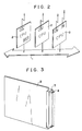
- a conventional hardwear structure of a multi-microcomputer system uses a plurality of CPU boards each having a central processing unit built thereon, and these CPU boards are mounted in a frame with their main surfaces parallel with each other.
- the lead conductors which are terminated at the inside edge of each CPU board, are connected to a bus cable extending behind the frame via an appropriate connector.
- a plurality of air conditioning fans 21 are arranged along the line of CPU boards 20.
- CPU boards which are positioned near each fan will be cooled more than those which are positioned far from each fan, and therefore, it is difficult that all CPU boards are cooled evenly and kept at same temperature.
- a parallel system bus structure comprises a plurality of bus wire-printed boards each having a plurality of signal conductors of equal length extending radially from a common contact centre, the bus wire-printed boards being spaced apart along an axis; and a plurality of stationary connectors each being connected to selected signal conductors and being adapted to mate with the edge connector of a CPU board, the stationary connectors being arranged around the bus wire- printed boards, whereby the structure permits connection between selected signal conductors on each bus wire-printed board and selected terminals on each of a plurality of CPU boards, which are positioned in use around the bus wire-printed boards.
- the present invention provides an improved parallel system bus structure which permits interboard signal paths to be equal and as short as possible regardless of the number of CPU boards used, thereby simplifying signal transmission controlling, and increasing the inter-CPU board communication speed to the maximum possible.
- all CPU boards are electrically connected to each other by selected two radial signal conductors.
- the present invention also provides an improved parallel system bus structure which permits even cooling of all CPU boards used, thereby keeping them at a given constant temperature.
- At least one bus wire-printed board is composed of a plurality of layers each bearing a plurality of signal conductors and a common contact centre connected thereto.
- signal conductors are provided at an increased density.
- Each bus wire-printed board may have a dielectric layer bearing a plurality of ground conductors on its undersurface, extending parallel to the signal conductors on its uppersurface so that the signal conductors are shielded.
- the bus structure further comprises at least one air conditioning fan above or below the vertical arrangement of said bus wire-printed boards on its central axis. All CPU boards will be evenly cooled and kept at an equal temperature.
- Inter-CPU board communication will be performed via a group of radial signal conductors on the bus-printed board, which radial signal conductors are connected to the lead conductors of each CPU board.
- Such multi-bus was designed for use in a multi-microprocessor system having a plurality of microprocessors built therein. As seen from Fig.2, these microprocessors are connected to each other by a Parallel System Bus 1.
- CPU boards there are two kinds of CPU boards to be used in such a multi-microprocessor system, i.e., one (“Single-High Board”) equipped with a single board connector 3 on its terminal edge (See Fig. 3), and the other("Double-High Board”) equipped with two board connectors on its terminal edge.
- Single-High Board equipped with a single board connector 3 on its terminal edge
- Double-High Board equipped with two board connectors on its terminal edge
- a board connector 3 has 32 connector pins 4 arranged each in three lines (96 connector pins in total).
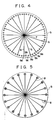
- Fig.4 is a plan view of the upper layer in a three-layer bus-printed board 5, which is made of epoxy resin. Signal conductors are indicated at 6; and terminals for the signal conductors in the upper layer, intermediate layer and lower layer are indicated at 9a, 9b and 9c.
- Each layer has 20 signal conductors 6 of equal length extending radially from its center common contact 7 at regular angular spaces.
- the ground conductors 8 are arranged in the same pattern as the signal conductors 6 so that they may be in registration with the overlying signal conductors 6.
- Fig.6 shows diagrammatically the manner in which signal conductors 6 and corresponding ground conductors 8 are arranged at different levels in the form of lamination.
- a bus-printed board 5 may be composed of three bus layers each having signal and ground conductors (or six sub-layers each having signal or ground conductors).
- the signal conductors 6 in each layer are arranged offset from the signal conductors 6 in the other layers, and all ground conductors 8 are grounded.
- Fig.7 shows that the signal conductors 6 in upper layer (solid lines), intermediate layer (dot-and-dash lines) and lower layer (broken lines) are arranged offset from the signal conductors 6 in the other layers.
- each signal conductor 6 is electrically connected to a terminal 9a, 9b or 9c by soldering and lining its pin hole 10a, 10b or 10C with a soldering material.
- a bus-printed board has 20 x 3 pin holes for the signal conductors 6 in three layers. Three pin holes 10a, 10b and 10c make up a single set (See Fig.5).
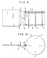
- bus-printed boards 5 are arranged vertically at regular spaces on four support rods 11, which stand on a frame (not shown).
- stationary conectors 12 are fixed to the frame, and all terminals of each stationary connector 12 are connected to the pin holes with the aid of L-shaped metals 13.
- CPU boards 2 standing upright are connected to the bus-printed boards 5 with their connector pins 4 inserted in the pin holes of the stationary connector 12.
- each set of three pin holes 10a, 10b and 10c receive three pins 4 at same level (See Figs.9 and 10).
- Each CPU board 2 is held by slidably inserting its upper and lower edges in upper and lower guide slots of the frame (not shown).
- a desired number of CPU boards 2 are arranged radial ly on the circumferences of twelve bus-printed disks 5.
- Air-conditioning fans 14 and 15 are put above and below the bus-printed disk column.
- the standard distance between adjacent CPU boards when connected to a Parallel System Bus is 0.8 inches (20.32mm).
- a longest data bus commercially available is 16.8 inches long. Therefore, twenty CPU boards can be connected to such data bus at standard intervals of 0.8 inches, and if CPU boards of "board-add-on" type (in which type a CPU board has a small board added thereon) are used, a less number of CPU boards are permitted.
- twenty CPU boards of "board-add-on” type can be connected to the circumference of a bus disk bearing spoke-like conductors because these CPU boards are arranged at regular angular intervals, leaving a divergent space between adjacent CPU boads, which divergent space is large enough to accommoadate the extra small board.
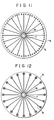
- Figs. 11 and 12 show another pattern of signal conductors 6 and ground conductors 8. As shown, each common center contact 7 is a small ring whose aperture 16 permits insertion of a support rod to hold a bus-printed disk 5.
- the signal path between selected CPU boards cannot be exactly same, but can be substantially twice as long as a radial signal conductor.
- the radial arrangement of signal conductors in a parallel system bus permits connection of selected CPU boards via equal length of signal path, no matter how many CPU boards may be used. Therefore, no timed control is required in transmission of signals between selected CPU boards via the bus, and accordingly communication speed will be increased to meet highly functional computer's requirements.
- Signal conductors can be printed on a relatively small disk at an increased density. Accordingly, the space occupied by the bus may be reduced.
- Air-conditioning fans below and/or above the bus disk column permit even cooling of the CPU boards surrounding the bus disk column to keep them at equal temperature.
Landscapes
- Engineering & Computer Science (AREA)
- Theoretical Computer Science (AREA)
- General Engineering & Computer Science (AREA)
- Microelectronics & Electronic Packaging (AREA)
- Computer Hardware Design (AREA)
- Physics & Mathematics (AREA)
- General Physics & Mathematics (AREA)
- Combinations Of Printed Boards (AREA)
- Bus Control (AREA)
- Multi Processors (AREA)
- Small-Scale Networks (AREA)
- Jib Cranes (AREA)
- Coupling Device And Connection With Printed Circuit (AREA)
Applications Claiming Priority (2)
| Application Number | Priority Date | Filing Date | Title |
|---|---|---|---|
| JP102909/89 | 1989-04-21 | ||
| JP1102909A JP2591677B2 (ja) | 1989-04-21 | 1989-04-21 | 放射型・パラレル・システムバス |
Publications (2)
| Publication Number | Publication Date |
|---|---|
| EP0394031A1 true EP0394031A1 (de) | 1990-10-24 |
| EP0394031B1 EP0394031B1 (de) | 1994-12-28 |
Family
ID=14339982
Family Applications (1)
| Application Number | Title | Priority Date | Filing Date |
|---|---|---|---|
| EP90304192A Expired - Lifetime EP0394031B1 (de) | 1989-04-21 | 1990-04-19 | Bus-Struktur für Parallelsystem |
Country Status (10)
| Country | Link |
|---|---|
| US (1) | US5060111A (de) |
| EP (1) | EP0394031B1 (de) |
| JP (1) | JP2591677B2 (de) |
| KR (1) | KR930002330B1 (de) |
| AT (1) | ATE116514T1 (de) |
| AU (1) | AU623001B2 (de) |
| CA (1) | CA2014571C (de) |
| DE (1) | DE69015414T2 (de) |
| IL (1) | IL94099A (de) |
| NZ (1) | NZ233375A (de) |
Cited By (8)
| Publication number | Priority date | Publication date | Assignee | Title |
|---|---|---|---|---|
| EP0466394A2 (de) * | 1990-07-09 | 1992-01-15 | Graphico Co. Ltd. | Steckverbinderbaugruppe |
| EP0486231A2 (de) * | 1990-11-16 | 1992-05-20 | Graphico Co. Ltd. | Paralleles Verarbeitungssystem |
| EP0488057A1 (de) * | 1990-11-21 | 1992-06-03 | Balu Balakrishnan | Integrierte Rückwandverbindungsarchitektur |
| EP0604333A1 (de) * | 1992-12-24 | 1994-06-29 | Advanced Computer Research Institute S.A.R.L. | Plattenverbindungsanordnung eines schnellen Datenverarbeitungssystems |
| EP0718931A3 (de) * | 1994-12-22 | 1999-03-31 | AT&T Corp. | Zylindrische Verbundrückwandleiterplatte |
| EP3399385A1 (de) * | 2013-06-07 | 2018-11-07 | Apple Inc. | Computerinnenarchitektur |
| US10248171B2 (en) | 2013-06-07 | 2019-04-02 | Apple Inc. | Desktop electronic device |
| US11899509B2 (en) | 2013-06-07 | 2024-02-13 | Apple Inc. | Computer housing |
Families Citing this family (27)
| Publication number | Priority date | Publication date | Assignee | Title |
|---|---|---|---|---|
| JP2626698B2 (ja) * | 1989-06-15 | 1997-07-02 | 株式会社 グラフィコ | 放射型・パラレル・システムバス |
| US5119273A (en) * | 1990-01-29 | 1992-06-02 | The United States Of America As Represented By The Secretary Of The Navy | High speed parallel backplane |
| US5210682A (en) * | 1990-10-19 | 1993-05-11 | Graphico Co., Ltd. | Radial type of parallel system bus structure having pairs of conductor lines with impedance matching elements |
| JP2700837B2 (ja) * | 1990-10-19 | 1998-01-21 | 株式会社 グラフィコ | 放射型・パラレル・システムバスにおける基板接続装置 |
| US5150279A (en) * | 1991-03-18 | 1992-09-22 | International Business Machines Corporation | High performance computer system with platters and unidirectional storage modules therebetween |
| EP0506224A3 (en) * | 1991-03-26 | 1994-05-11 | Ibm | Computer system package |
| JPH04320509A (ja) * | 1991-04-19 | 1992-11-11 | Gurafuiko:Kk | 並列処理装置 |
| DE4223893C2 (de) * | 1992-07-21 | 2002-10-17 | Philips Corp Intellectual Pty | Rotierende Abtasteinrichtung |
| US5548734A (en) * | 1993-03-26 | 1996-08-20 | Intel Corporation | Equal length symmetric computer bus topology |
| JP2604121B2 (ja) * | 1994-09-06 | 1997-04-30 | アジアエレクトロニクス株式会社 | ル−プ・バス |
| US5696667A (en) * | 1996-04-15 | 1997-12-09 | Arizona Digital, Inc. | Backplane for high speed data processing system |
| US6052276A (en) * | 1997-10-27 | 2000-04-18 | Citicorp Development Center, Inc. | Passive backplane computer |
| US6078187A (en) * | 1997-05-23 | 2000-06-20 | Credence Systems Corporation | Hemispherical test head for integrated circuit tester employing radially distributed circuit cards |
| US5903432A (en) * | 1997-09-19 | 1999-05-11 | Intel Corportation | Computer package with a polygonal shaped motherboard |
| US6512396B1 (en) | 1999-01-29 | 2003-01-28 | Arizona Digital, Inc. | High speed data processing system and method |
| DE10130592C1 (de) * | 2001-06-27 | 2002-10-24 | Infineon Technologies Ag | Modulbaugruppe für Speicher-Module und Verfahren zu ihrer Herstellung |
| WO2005013649A2 (en) * | 2003-07-28 | 2005-02-10 | Derick Arripol | A housing assembly for stacking multiple computer modules |
| US7133289B2 (en) * | 2003-07-28 | 2006-11-07 | Derick Arippol | Housing assembly for stacking multiple computer modules |
| WO2009032144A2 (en) * | 2007-08-28 | 2009-03-12 | General Dynamics Advanced Information Systems, Inc. | System and method for interconnecting circuit boards |
| US8189345B2 (en) * | 2008-06-18 | 2012-05-29 | Lockheed Martin Corporation | Electronics module, enclosure assembly housing same, and related systems and methods |
| US8773864B2 (en) * | 2008-06-18 | 2014-07-08 | Lockheed Martin Corporation | Enclosure assembly housing at least one electronic board assembly and systems using same |
| CN201229538Y (zh) * | 2008-07-04 | 2009-04-29 | 鸿富锦精密工业(深圳)有限公司 | 电脑机箱 |
| US8842432B2 (en) * | 2012-09-22 | 2014-09-23 | Facebook, Inc. | Arrangement of computing assets in a data center |
| US9651999B1 (en) * | 2014-09-30 | 2017-05-16 | Apple Inc. | Electronic device with radially deployed components |
| TWM520229U (zh) * | 2015-07-16 | 2016-04-11 | 鋐寶科技股份有限公司 | 電子裝置 |
| US10499524B2 (en) | 2017-12-20 | 2019-12-03 | Capital One Services, Llc | Apparatus for mounting a processor for cluster computing |
| KR102364817B1 (ko) | 2020-08-12 | 2022-02-18 | 임상래 | 공기정화기를 구비한 지구의 |
Citations (3)
| Publication number | Priority date | Publication date | Assignee | Title |
|---|---|---|---|---|
| US3675083A (en) * | 1970-09-14 | 1972-07-04 | Digital Equipment Corp | Universal bus arrangement for data processing systems |
| FR2459605A1 (fr) * | 1979-06-14 | 1981-01-09 | Guenin Jean Pierre | Equipement d'interconnexions de cartes a circuits imprimes |
| US4679872A (en) * | 1986-01-27 | 1987-07-14 | Coe Larry D | Cylindrical back plane structure for receiving printed circuit boards |
Family Cites Families (9)
| Publication number | Priority date | Publication date | Assignee | Title |
|---|---|---|---|---|
| DE1563403B2 (de) * | 1966-09-15 | 1977-02-17 | Siemens AG, 1000 Berlin und 8000 München | Steuerbarer hochspannungsstromrichter |
| US3794784A (en) * | 1973-05-07 | 1974-02-26 | Atlantic Richfield Co | Rotary wafer switch having rotor mounted, spiral arranged axial bridging contacts |
| US3812381A (en) * | 1973-06-04 | 1974-05-21 | Gen Motors Corp | Circuit board connector with screw fastener |
| JPS5724679B2 (de) * | 1974-04-05 | 1982-05-25 | ||
| US3967874A (en) * | 1975-09-30 | 1976-07-06 | Calabro Anthony Denis | Uniformly cooled printed circuit board mounting assembly |
| JPS5526745U (de) * | 1978-08-07 | 1980-02-21 | ||
| US4399484A (en) * | 1981-03-10 | 1983-08-16 | The United States Of America As Represented By The Secretary Of The Air Force | Integral electric module and assembly jet cooling system |
| JPS5958964U (ja) * | 1982-10-12 | 1984-04-17 | 三菱電機株式会社 | プリント基板 |
| US4888663A (en) * | 1986-03-25 | 1989-12-19 | Hughes Aircraft Company | Cooling system for electronic assembly |
-
1989
- 1989-04-21 JP JP1102909A patent/JP2591677B2/ja not_active Expired - Lifetime
-
1990
- 1990-04-10 US US07/507,194 patent/US5060111A/en not_active Expired - Lifetime
- 1990-04-12 AU AU53238/90A patent/AU623001B2/en not_active Ceased
- 1990-04-12 CA CA002014571A patent/CA2014571C/en not_active Expired - Fee Related
- 1990-04-18 IL IL9409990A patent/IL94099A/en not_active IP Right Cessation
- 1990-04-19 AT AT90304192T patent/ATE116514T1/de not_active IP Right Cessation
- 1990-04-19 DE DE69015414T patent/DE69015414T2/de not_active Expired - Fee Related
- 1990-04-19 KR KR1019900005490A patent/KR930002330B1/ko not_active IP Right Cessation
- 1990-04-19 EP EP90304192A patent/EP0394031B1/de not_active Expired - Lifetime
- 1990-04-19 NZ NZ233375A patent/NZ233375A/en unknown
Patent Citations (3)
| Publication number | Priority date | Publication date | Assignee | Title |
|---|---|---|---|---|
| US3675083A (en) * | 1970-09-14 | 1972-07-04 | Digital Equipment Corp | Universal bus arrangement for data processing systems |
| FR2459605A1 (fr) * | 1979-06-14 | 1981-01-09 | Guenin Jean Pierre | Equipement d'interconnexions de cartes a circuits imprimes |
| US4679872A (en) * | 1986-01-27 | 1987-07-14 | Coe Larry D | Cylindrical back plane structure for receiving printed circuit boards |
Non-Patent Citations (1)
| Title |
|---|
| IBM TECHNICAL DISCLOSURE BULLETIN. vol. 32, no. 2, July 1989, NEW YORK US pages 177 - 179; "ALTERNATIVE PACKAGING FOR A PERSONAL COMPUTER" * |
Cited By (22)
| Publication number | Priority date | Publication date | Assignee | Title |
|---|---|---|---|---|
| EP0466394A2 (de) * | 1990-07-09 | 1992-01-15 | Graphico Co. Ltd. | Steckverbinderbaugruppe |
| EP0466394A3 (en) * | 1990-07-09 | 1993-05-12 | Graphico Co. Ltd. | Connector assembly |
| EP0486231A2 (de) * | 1990-11-16 | 1992-05-20 | Graphico Co. Ltd. | Paralleles Verarbeitungssystem |
| EP0486231A3 (en) * | 1990-11-16 | 1993-05-12 | Graphico Co. Ltd. | Parallel processing system |
| EP0488057A1 (de) * | 1990-11-21 | 1992-06-03 | Balu Balakrishnan | Integrierte Rückwandverbindungsarchitektur |
| EP0604333A1 (de) * | 1992-12-24 | 1994-06-29 | Advanced Computer Research Institute S.A.R.L. | Plattenverbindungsanordnung eines schnellen Datenverarbeitungssystems |
| FR2700069A1 (fr) * | 1992-12-24 | 1994-07-01 | Adv Comp Res Inst Sarl | Système d'interconnexion de cartes d'un système informatique rapide. |
| EP0718931A3 (de) * | 1994-12-22 | 1999-03-31 | AT&T Corp. | Zylindrische Verbundrückwandleiterplatte |
| US10248171B2 (en) | 2013-06-07 | 2019-04-02 | Apple Inc. | Desktop electronic device |
| US11256307B2 (en) | 2013-06-07 | 2022-02-22 | Apple Inc. | Desktop electronic device |
| EP3399385A1 (de) * | 2013-06-07 | 2018-11-07 | Apple Inc. | Computerinnenarchitektur |
| US10254805B2 (en) | 2013-06-07 | 2019-04-09 | Apple Inc. | Desktop electronic device |
| US10539984B2 (en) | 2013-06-07 | 2020-01-21 | Apple Inc. | Computer housing |
| US10725507B2 (en) | 2013-06-07 | 2020-07-28 | Apple Inc. | Desktop electronic device |
| US10845852B2 (en) | 2013-06-07 | 2020-11-24 | Apple Inc. | Desktop electronic device |
| EP3399386A1 (de) * | 2013-06-07 | 2018-11-07 | Apple Inc. | Computerinnenarchitektur |
| US11256306B2 (en) | 2013-06-07 | 2022-02-22 | Apple Inc. | Computer housing |
| EP3964924A1 (de) * | 2013-06-07 | 2022-03-09 | Apple Inc. | Computerinnenarchitektur |
| US11650634B2 (en) | 2013-06-07 | 2023-05-16 | Apple Inc. | Desktop electronic device |
| US11899509B2 (en) | 2013-06-07 | 2024-02-13 | Apple Inc. | Computer housing |
| US11899511B2 (en) | 2013-06-07 | 2024-02-13 | Apple Inc. | Computer housing |
| EP4290335A3 (de) * | 2013-06-07 | 2024-03-06 | Apple Inc. | Computerinnenarchitektur |
Also Published As
| Publication number | Publication date |
|---|---|
| JPH02281359A (ja) | 1990-11-19 |
| DE69015414D1 (de) | 1995-02-09 |
| US5060111A (en) | 1991-10-22 |
| IL94099A0 (en) | 1991-01-31 |
| IL94099A (en) | 1995-01-24 |
| DE69015414T2 (de) | 1995-08-17 |
| NZ233375A (en) | 1992-08-26 |
| KR900016883A (ko) | 1990-11-14 |
| CA2014571C (en) | 1998-06-09 |
| ATE116514T1 (de) | 1995-01-15 |
| AU5323890A (en) | 1990-10-25 |
| AU623001B2 (en) | 1992-04-30 |
| CA2014571A1 (en) | 1990-10-21 |
| KR930002330B1 (ko) | 1993-03-29 |
| EP0394031B1 (de) | 1994-12-28 |
| JP2591677B2 (ja) | 1997-03-19 |
Similar Documents
| Publication | Publication Date | Title |
|---|---|---|
| EP0394031A1 (de) | Bus-Struktur für Parallelsystem | |
| US5091822A (en) | Radial type of parallel system bus structure with printed, twisted conductor lines | |
| US7719843B2 (en) | Multiple drive plug-in cable | |
| US6504717B1 (en) | Failure-tolerant high-density card rack cooling system and method | |
| CA2018072C (en) | Feature board with automatic adjustment to slot position | |
| EP0574133B1 (de) | Schalt-Zwischenebene und Zwischenverbindungssystem zum Untereinanderverbinden einer grossen Anzahl von Signalen | |
| US4575780A (en) | Backpanel assemblies | |
| US6232564B1 (en) | Printed wiring board wireability enhancement | |
| US5565654A (en) | Printed circuit board for plug-type connections | |
| US3197766A (en) | Stacked circuit boards | |
| US5497037A (en) | Method and apparatus for decoupling of unused power supply pins of a printed circuit board capable of operating at a plurality of predetermined voltages | |
| US6154373A (en) | High density cross-connection system | |
| EP0715489A2 (de) | Leiterplattenanordnung | |
| EP2079293B1 (de) | Rückwandplatine und Kommunikationsvorrichtung | |
| EP0718931B1 (de) | Zylindrische Verbundrückwandleiterplatte | |
| US5640606A (en) | Multifunction disk chassis having audio/video buses for exclusively transmitting audio/video material and plurality of edge connector pairs for connecting with plurality of hard disk drives | |
| US3983459A (en) | Circuit board spacer | |
| JP2619540B2 (ja) | 自動組立機の部品実装順序決定処理方法 | |
| EP0599504B1 (de) | Massenspeichersubsystem | |
| CN111602472B (zh) | 用于高速、高密度电连接器的背板占板区 | |
| JPH0622007B2 (ja) | バスを2つ含む情報システムアーキテクチャ | |
| US6116913A (en) | Interconnection unit | |
| GB1566306A (en) | Electronic printed circuit assemblies | |
| JPH0821456B2 (ja) | マザーボードとこれを備えた外部記憶装置 |
Legal Events
| Date | Code | Title | Description |
|---|---|---|---|
| PUAI | Public reference made under article 153(3) epc to a published international application that has entered the european phase |
Free format text: ORIGINAL CODE: 0009012 |
|
| AK | Designated contracting states |
Kind code of ref document: A1 Designated state(s): AT CH DE DK FR GB IT LI NL SE |
|
| 17P | Request for examination filed |
Effective date: 19910404 |
|
| 17Q | First examination report despatched |
Effective date: 19930608 |
|
| GRAA | (expected) grant |
Free format text: ORIGINAL CODE: 0009210 |
|
| AK | Designated contracting states |
Kind code of ref document: B1 Designated state(s): AT CH DE DK FR GB IT LI NL SE |
|
| PG25 | Lapsed in a contracting state [announced via postgrant information from national office to epo] |
Ref country code: IT Free format text: LAPSE BECAUSE OF FAILURE TO SUBMIT A TRANSLATION OF THE DESCRIPTION OR TO PAY THE FEE WITHIN THE PRE;WARNING: LAPSES OF ITALIAN PATENTS WITH EFFECTIVE DATE BEFORE 2007 MAY HAVE OCCURRED AT ANY TIME BEFORE 2007. THE CORRECT EFFECTIVE DATE MAY BE DIFFERENT FROM THE ONE RECORDED.SCRIBED TIME-LIMIT Effective date: 19941228 Ref country code: DK Effective date: 19941228 Ref country code: AT Effective date: 19941228 Ref country code: CH Effective date: 19941228 Ref country code: NL Effective date: 19941228 Ref country code: LI Effective date: 19941228 |
|
| REF | Corresponds to: |
Ref document number: 116514 Country of ref document: AT Date of ref document: 19950115 Kind code of ref document: T |
|
| REF | Corresponds to: |
Ref document number: 69015414 Country of ref document: DE Date of ref document: 19950209 |
|
| ET | Fr: translation filed | ||
| PG25 | Lapsed in a contracting state [announced via postgrant information from national office to epo] |
Ref country code: SE Effective date: 19950328 |
|
| REG | Reference to a national code |
Ref country code: CH Ref legal event code: PL |
|
| NLV1 | Nl: lapsed or annulled due to failure to fulfill the requirements of art. 29p and 29m of the patents act | ||
| PLBE | No opposition filed within time limit |
Free format text: ORIGINAL CODE: 0009261 |
|
| STAA | Information on the status of an ep patent application or granted ep patent |
Free format text: STATUS: NO OPPOSITION FILED WITHIN TIME LIMIT |
|
| 26N | No opposition filed | ||
| REG | Reference to a national code |
Ref country code: GB Ref legal event code: 732E |
|
| REG | Reference to a national code |
Ref country code: FR Ref legal event code: TP |
|
| REG | Reference to a national code |
Ref country code: GB Ref legal event code: IF02 |
|
| PGFP | Annual fee paid to national office [announced via postgrant information from national office to epo] |
Ref country code: FR Payment date: 20060410 Year of fee payment: 17 |
|
| PGFP | Annual fee paid to national office [announced via postgrant information from national office to epo] |
Ref country code: DE Payment date: 20060413 Year of fee payment: 17 |
|
| PGFP | Annual fee paid to national office [announced via postgrant information from national office to epo] |
Ref country code: GB Payment date: 20060419 Year of fee payment: 17 |
|
| GBPC | Gb: european patent ceased through non-payment of renewal fee |
Effective date: 20070419 |
|
| PG25 | Lapsed in a contracting state [announced via postgrant information from national office to epo] |
Ref country code: DE Free format text: LAPSE BECAUSE OF NON-PAYMENT OF DUE FEES Effective date: 20071101 |
|
| PG25 | Lapsed in a contracting state [announced via postgrant information from national office to epo] |
Ref country code: GB Free format text: LAPSE BECAUSE OF NON-PAYMENT OF DUE FEES Effective date: 20070419 |
|
| PG25 | Lapsed in a contracting state [announced via postgrant information from national office to epo] |
Ref country code: FR Free format text: LAPSE BECAUSE OF NON-PAYMENT OF DUE FEES Effective date: 20070430 |