EP0391115B1 - Arbeitstisch - Google Patents
Arbeitstisch Download PDFInfo
- Publication number
- EP0391115B1 EP0391115B1 EP90105067A EP90105067A EP0391115B1 EP 0391115 B1 EP0391115 B1 EP 0391115B1 EP 90105067 A EP90105067 A EP 90105067A EP 90105067 A EP90105067 A EP 90105067A EP 0391115 B1 EP0391115 B1 EP 0391115B1
- Authority
- EP
- European Patent Office
- Prior art keywords
- clamping
- workbench
- board
- work
- legs
- Prior art date
- Legal status (The legal status is an assumption and is not a legal conclusion. Google has not performed a legal analysis and makes no representation as to the accuracy of the status listed.)
- Expired - Lifetime
Links
- 210000001364 upper extremity Anatomy 0.000 claims description 5
- 238000003801 milling Methods 0.000 claims description 3
- 230000008878 coupling Effects 0.000 abstract description 4
- 238000010168 coupling process Methods 0.000 abstract description 4
- 238000005859 coupling reaction Methods 0.000 abstract description 4
- 230000005484 gravity Effects 0.000 description 2
- 235000004443 Ricinus communis Nutrition 0.000 description 1
- 240000000528 Ricinus communis Species 0.000 description 1
- 238000009434 installation Methods 0.000 description 1
Images


Classifications
-
- B—PERFORMING OPERATIONS; TRANSPORTING
- B23—MACHINE TOOLS; METAL-WORKING NOT OTHERWISE PROVIDED FOR
- B23D—PLANING; SLOTTING; SHEARING; BROACHING; SAWING; FILING; SCRAPING; LIKE OPERATIONS FOR WORKING METAL BY REMOVING MATERIAL, NOT OTHERWISE PROVIDED FOR
- B23D47/00—Sawing machines or sawing devices working with circular saw blades, characterised only by constructional features of particular parts
- B23D47/02—Sawing machines or sawing devices working with circular saw blades, characterised only by constructional features of particular parts of frames; of guiding arrangements for work-table or saw-carrier
- B23D47/025—Sawing machines or sawing devices working with circular saw blades, characterised only by constructional features of particular parts of frames; of guiding arrangements for work-table or saw-carrier of tables
-
- B—PERFORMING OPERATIONS; TRANSPORTING
- B23—MACHINE TOOLS; METAL-WORKING NOT OTHERWISE PROVIDED FOR
- B23D—PLANING; SLOTTING; SHEARING; BROACHING; SAWING; FILING; SCRAPING; LIKE OPERATIONS FOR WORKING METAL BY REMOVING MATERIAL, NOT OTHERWISE PROVIDED FOR
- B23D57/00—Sawing machines or sawing devices not covered by one of the preceding groups B23D45/00 - B23D55/00
- B23D57/0092—Sawing machines or sawing devices not covered by one of the preceding groups B23D45/00 - B23D55/00 dismountable, collapsible or transportable, e.g. by means of a carrying case
-
- B—PERFORMING OPERATIONS; TRANSPORTING
- B25—HAND TOOLS; PORTABLE POWER-DRIVEN TOOLS; MANIPULATORS
- B25H—WORKSHOP EQUIPMENT, e.g. FOR MARKING-OUT WORK; STORAGE MEANS FOR WORKSHOPS
- B25H1/00—Work benches; Portable stands or supports for positioning portable tools or work to be operated on thereby
- B25H1/0021—Stands, supports or guiding devices for positioning portable tools or for securing them to the work
- B25H1/0042—Stands
- B25H1/005—Stands attached to a workbench
-
- B—PERFORMING OPERATIONS; TRANSPORTING
- B25—HAND TOOLS; PORTABLE POWER-DRIVEN TOOLS; MANIPULATORS
- B25H—WORKSHOP EQUIPMENT, e.g. FOR MARKING-OUT WORK; STORAGE MEANS FOR WORKSHOPS
- B25H1/00—Work benches; Portable stands or supports for positioning portable tools or work to be operated on thereby
- B25H1/02—Work benches; Portable stands or supports for positioning portable tools or work to be operated on thereby of table type
- B25H1/04—Work benches; Portable stands or supports for positioning portable tools or work to be operated on thereby of table type portable
-
- Y—GENERAL TAGGING OF NEW TECHNOLOGICAL DEVELOPMENTS; GENERAL TAGGING OF CROSS-SECTIONAL TECHNOLOGIES SPANNING OVER SEVERAL SECTIONS OF THE IPC; TECHNICAL SUBJECTS COVERED BY FORMER USPC CROSS-REFERENCE ART COLLECTIONS [XRACs] AND DIGESTS
- Y10—TECHNICAL SUBJECTS COVERED BY FORMER USPC
- Y10S—TECHNICAL SUBJECTS COVERED BY FORMER USPC CROSS-REFERENCE ART COLLECTIONS [XRACs] AND DIGESTS
- Y10S269/00—Work holders
- Y10S269/901—Collapsible or foldable work holder supporting structure
Definitions
- the invention relates to a work table equipped as a workbench and at the same time as a circular saw table, the table surface of which is subdivided into a workbench plate and a circular saw clamping plate, the clamping plate being pivotable relative to the workbench plate.
- Such a combined work table is known from DE-A-28 19 033.
- the known work table is designed as a piece of furniture to be anchored stationary on a wall, the upper side of which forms a workbench plate, below which a pivoting plate carrying a work machine is articulated on the piece of furniture, which moves from this lowered position to a work position at the height of the workbench can be swiveled up translationally at the front.
- do-it-yourselfers are often not able to set up such a stationary piece of furniture.
- Do-it-yourselfers generally want a work table that can be folded up to save space when not in use, which they can use in a garage, for example, and which can be placed or hung on a garage wall as a flat package when not in use.
- the swivel plate also tends to vibrate in its swiveled-up working position, which can at most be eliminated by complex locking and tensioning devices.
- the invention has for its object to further develop a generic combined work table in such a way that, despite its large total table surface, it is foldable on the one hand as a flat, clearable package and on the other hand is stable in the open position and has a high, non-oscillating inherent stability of its divided total table surface, the Circular saw or the like. It should also be easy to assemble and disassemble.
- the continuous upper frame ensures a stable, non-oscillating support of the workbench plate and clamping plate, so that the entire table surface formed by the workbench plate and clamping plate can be used as a heavy-duty working surface.
- the structures belonging to the sawing area do not hinder work on the workbench, and conversely the workbench structures, especially their clamping device, do not interfere with the work on the circular saw or other machines attached to this clamping plate, such as jigsaw, milling machines and the like
- a replacement or removal of the circular saw, jigsaw or the like can be carried out conveniently, since the clamping plate can now be pivoted into an obliquely upward position above the workbench plate, in which its underside is accessible for assembly or disassembly of the saw, while at the same time maintain the top of the clamping plate as far from the workbench plate that the circular saw blade, jigsaw or the respective tool does not hit the workbench.
- the clamping plate rests on the upper frame, so that it represents a quasi rigid extension of the workbench plate. Due to the articulation of the legs only in the area of the workbench top and because they can be folded under the clamp plate there is the further advantage that the work table is not only collapsible into a flat package, but that the longitudinal dimension of the collapsed package is only slightly larger than the longitudinal dimension of the total table surface. In the open position, the platen protrudes a little way beyond the footprint defined by the four legs.
- the two table leg coupling rods can carry a tool tray on which the tools can be placed ready for access.
- this tool tray provides additional stiffening of the table base and a further shift of the center of gravity towards the workbench top, which further increases the stability of the work table.
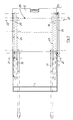
- the work table has a rectangular upper frame 1, which carries an approximately rectangular workbench plate 2 on one side and a clamping plate 3 on the other longitudinal side, which can be pivoted about an axis 4 in the Upper frame 1 is mounted and can be pivoted into an obliquely upward position 3 'over the workbench plate 2.
- the platen 3 is equipped with a slot 5 for a circular saw blade and with a hole 6 for a milling machine or a jigsaw blade in the usual way.
- the circular saw blade can be covered by a hood 7, which is pivotably mounted on one side of the workbench plate 2 via a lever 8 bent into a U-shape.
- a holder and guide 9 for a pivotable guide stop 10 is provided on the upper frame 1.
- a clamping device 11 is arranged on the workbench on the edge side of the workbench 2 opposite the clamping plate 3, and a handle 12 is located on the same side in a recess in the workbench.
- a standard clamping ring 14 for standard clamping shanks of 43 mm ⁇ arranged, which allows a hand drill with a corresponding adapter standard pin to be clamped above the workbench 2.
- a clamping ring 15 is also screwed laterally onto the workbench plate or its upper frame 1, which allows the clamping of a hand drill 16 laterally next to the plate 2.
- the upper frame 1 common for workbench plate 2 and clamping plate 3 is supported only in the area of workbench plate 2 by four legs 17, 18, 19, 20, which can be folded about articulation axes 21, 22.
- the legs 17, 18 and 19, 20 are each connected by a coupling rod 23, 24, which carry a tool tray 25 adjacent to the rear legs 18, 20.
- the two on one side of the table arranged legs 17, 18 are also connected to one another by a locking rod 26 which is articulated to the lower end of the rear leg 18 and which can be locked and unlocked on the leg 17 in the upper region at position 27.
- the legs are loaded by tension springs 28 clamped on the rear legs 18, 20 and on the rear edge of the workbench, by means of which the unfolded position of the table is secured.
- the two legs 19, 20 are stiffened by a two-part locking device 29 which can be bent upwards. Furthermore, the front legs 17, 19 are each provided with a roller 30 on their side facing the rear legs 18, 20, which lie somewhat above the installation floor when the work table is open. Finally, a step plate 31 is pivotally mounted on the two front legs 17, 19, on which the user can stand when carrying out sawing work, so as to increase the stability of the table.
- the two rear legs 18, 20 are connected to one another at the bottom by a footstep bar 32.
- the locking device 29 When collapsing, the locking device 29 is first unlocked for a buckling upwards, and then the locking rod 26 detached from the front leg 17 and pivoted backwards as a second handle. With the other hand, the operator grips the handle 12 provided at the rear edge of the table, which is pulled while a counter pressure is exerted on the step bar 32 with one foot. After passing through the already partially folded position according to FIG.
- the table with its rear legs 18, 20 is placed back on the floor, after which the weight of the table, in particular when the sawing machine is clamped in, is sufficient to completely overcome the restoring force of the springs 28 collapse, however, the tension spring 28 - based on the upper articulation points 22 of the rear legs 18, 20 - are guided into an over-center position, in which they secure the folded position of the table, cf. Fig. 7.
- the table can be moved on castors 30 like a wheelbarrow when folded, or can be stored upright to save space.
- the handle bar 26 is attached to the table.
- the locking rod 26 is used again as a handle, and the legs are pulled away from the upper frame by means of this rod 26, the springs 28 again being passed over the dead center and then essentially taking over the further opening of the table.
- a two-part, snap-in locking device 33 is provided on the legs 17, 18, which runs parallel to the locking device 29. Otherwise the same structure is provided.
- the operator stands in front of the legs 17, 18 when folded, and the table is gripped here by the handle 12 and the other, for example, on the opposite edge of the table top.
Landscapes
- Engineering & Computer Science (AREA)
- Mechanical Engineering (AREA)
- Workshop Equipment, Work Benches, Supports, Or Storage Means (AREA)
- Preparation Of Compounds By Using Micro-Organisms (AREA)
- Peptides Or Proteins (AREA)
- Medicines Containing Antibodies Or Antigens For Use As Internal Diagnostic Agents (AREA)
- Massaging Devices (AREA)
- Vending Machines For Individual Products (AREA)
- Sawing (AREA)
- Electrical Discharge Machining, Electrochemical Machining, And Combined Machining (AREA)
- Forklifts And Lifting Vehicles (AREA)
Applications Claiming Priority (2)
| Application Number | Priority Date | Filing Date | Title |
|---|---|---|---|
| DE3910826A DE3910826C1 (enExample) | 1989-04-04 | 1989-04-04 | |
| DE3910826 | 1989-04-04 |
Publications (3)
| Publication Number | Publication Date |
|---|---|
| EP0391115A2 EP0391115A2 (de) | 1990-10-10 |
| EP0391115A3 EP0391115A3 (de) | 1991-01-23 |
| EP0391115B1 true EP0391115B1 (de) | 1993-06-09 |
Family
ID=6377799
Family Applications (1)
| Application Number | Title | Priority Date | Filing Date |
|---|---|---|---|
| EP90105067A Expired - Lifetime EP0391115B1 (de) | 1989-04-04 | 1990-03-17 | Arbeitstisch |
Country Status (8)
| Country | Link |
|---|---|
| US (1) | US5067535A (enExample) |
| EP (1) | EP0391115B1 (enExample) |
| AT (1) | ATE90261T1 (enExample) |
| DE (2) | DE3910826C1 (enExample) |
| DK (1) | DK0391115T3 (enExample) |
| ES (1) | ES2042105T3 (enExample) |
| FI (1) | FI94605C (enExample) |
| NO (1) | NO901520L (enExample) |
Cited By (1)
| Publication number | Priority date | Publication date | Assignee | Title |
|---|---|---|---|---|
| US7588255B2 (en) | 2004-11-10 | 2009-09-15 | Zag Industries, Ltd. | Collapsible clamping work table |
Families Citing this family (61)
| Publication number | Priority date | Publication date | Assignee | Title |
|---|---|---|---|---|
| GB9027775D0 (en) * | 1990-12-21 | 1991-02-13 | Black & Decker Inc | Workbench |
| DE69107603T2 (de) * | 1990-12-21 | 1995-06-14 | Black & Decker Inc | Werkbank und Werktisch. |
| GB9112119D0 (en) * | 1991-06-05 | 1991-07-24 | Ede Douglas | Combined tooling jig and work table |
| AU640105B3 (en) * | 1993-05-03 | 1993-08-12 | John Lindsay Walker | Portable workbench |
| USD364412S (en) | 1994-06-16 | 1995-11-21 | Emerson Electric Co. | Table saw |
| USD369260S (en) | 1994-07-07 | 1996-04-30 | Fred Cochrane | Workbench extender |
| US5863052A (en) * | 1994-10-27 | 1999-01-26 | Roman; Gregory S. | Collapsible carpentry work station and push cart combination |
| USD386624S (en) * | 1995-08-11 | 1997-11-25 | Black & Decker, Inc. | Workbench incorporating a universal drawer accessory |
| USD379042S (en) * | 1995-08-11 | 1997-05-06 | Black & Decker Inc. | Workbench universal drawer accessory |
| US5765273A (en) * | 1995-09-22 | 1998-06-16 | Black & Decker Inc. | Drill press having pivotable table |
| US5592981A (en) * | 1995-11-03 | 1997-01-14 | Tracrac, Inc. | Portable work bench having sliding connections for releasably and adjustably attaching accessories thereto |
| US5806947A (en) * | 1996-08-08 | 1998-09-15 | Black & Decker Inc. | Foldable workbench including universal tray |
| US5848743A (en) * | 1996-08-28 | 1998-12-15 | Tracrac, Inc. | Vehicle roof rack |
| US5836365A (en) * | 1997-06-19 | 1998-11-17 | Tracrac, Inc. | Portable work bench having multiple accessories |
| US5875828A (en) * | 1997-07-24 | 1999-03-02 | Black & Decker, Inc. | Portable work bench |
| US6182724B1 (en) * | 1999-09-07 | 2001-02-06 | Gin Cherng Chou | Foldable working bench |
| US6209597B1 (en) | 1999-09-08 | 2001-04-03 | Hal Calcote | Power tool mounting stand |
| US6435460B1 (en) * | 1999-11-04 | 2002-08-20 | Van Mark Products Corporation | Portable tool support stand |
| US6360797B1 (en) | 1999-12-28 | 2002-03-26 | One World Technologies, Inc. | Power tool and portable support assembly |
| US6578856B2 (en) * | 2000-01-10 | 2003-06-17 | W. Scott Kahle | Collapsible portable saw stand |
| GB2359040A (en) * | 2000-02-09 | 2001-08-15 | Geoffrey Manning | A transportable workbench |
| US7648155B1 (en) * | 2000-03-02 | 2010-01-19 | Wise Robert W | Universal mobile saw stand |
| US6240987B1 (en) * | 2000-03-23 | 2001-06-05 | Clinton D. Birkeland | Tool supporting device |
| GB2363366A (en) * | 2000-07-05 | 2001-12-19 | John Leslie Blackford | A trolley convertible into a height adjustable worktable |
| US6644158B2 (en) | 2000-10-19 | 2003-11-11 | Van Mark Products Corporation | Work table |
| DE10107495A1 (de) * | 2001-02-15 | 2002-08-22 | Wolfcraft Gmbh | Sägetisch |
| US6857456B2 (en) | 2001-08-14 | 2005-02-22 | Geoffrey Manning | Workbench |
| US6854314B2 (en) | 2001-09-14 | 2005-02-15 | Van Mark Products Corporation | Sheet metal tool stand |
| GB0203788D0 (en) * | 2002-02-19 | 2002-04-03 | Kent Frank M J | The folding of a clamping table |
| US6883793B2 (en) | 2002-09-17 | 2005-04-26 | Black & Decker Inc. | Portable workbench having collapsible support structure |
| US6848684B2 (en) | 2002-09-17 | 2005-02-01 | Black & Decker Inc. | Workbench having plastic clamping work surface |
| US6662838B1 (en) * | 2002-10-30 | 2003-12-16 | Graham, Iii Frank L. | Bench slide mount |
| US6786162B1 (en) | 2003-02-20 | 2004-09-07 | Randy E. Volkmer | Space-saver workbench |
| US7090210B2 (en) | 2003-08-05 | 2006-08-15 | Black & Decker Inc. | Folding bench with hand truck capabilities |
| US7131364B2 (en) | 2003-08-25 | 2006-11-07 | Eastway Fair Company, Ltd. | Collapsible stand for a bench-top power tool |
| US20050051940A1 (en) * | 2003-09-05 | 2005-03-10 | Zag Industries, Ltd. | Work stand |
| US6942229B2 (en) * | 2003-10-31 | 2005-09-13 | One World Technologies Limited | Collapsible stand for a bench-top power tool |
| US20050120922A1 (en) * | 2003-12-05 | 2005-06-09 | Brooks Nolan T. | Folding work table |
| US8096519B2 (en) * | 2004-03-12 | 2012-01-17 | Robert Bosch Gmbh | Collapsible rolling support stand |
| US20050279576A1 (en) * | 2004-06-21 | 2005-12-22 | Luc Robichaud | Workbench with removable tool support |
| US20060011191A1 (en) * | 2004-07-13 | 2006-01-19 | Elmer Vavricek | Tile saw stand |
| US7350549B2 (en) * | 2005-05-31 | 2008-04-01 | Carter Mark C | Folding work bench |
| US9376130B1 (en) * | 2007-01-12 | 2016-06-28 | Robert W. Wise | Self-jacking mobile saw stand WA9940 |
| US20080203704A1 (en) * | 2007-02-27 | 2008-08-28 | Mccracken Robert E | Foldable stand for supporting a power tool |
| US7628186B2 (en) * | 2007-04-04 | 2009-12-08 | Gary Joseph Blum | Portable workbench |
| US8113415B2 (en) * | 2007-06-07 | 2012-02-14 | Doben Limited | Modular welding fixture |
| US7882870B2 (en) * | 2007-11-23 | 2011-02-08 | Wy Peron Lee | Portable supporting frame for cutting machine |
| US8464994B2 (en) * | 2008-10-22 | 2013-06-18 | Rexon Industrial Corp., Ltd. | Folding tool stand |
| US8727297B2 (en) * | 2010-01-06 | 2014-05-20 | Ted N. Kelley, III | Music stand |
| US9512627B2 (en) * | 2010-05-10 | 2016-12-06 | L. Michael Taron | Collapsible saw horse |
| US10335873B2 (en) * | 2011-01-24 | 2019-07-02 | Ronald Wynne | Portable miter saw accessory |
| US8371541B2 (en) | 2011-03-28 | 2013-02-12 | Van Mark Products Corporation | Portable tool stand |
| US8910970B2 (en) * | 2011-06-10 | 2014-12-16 | Rexon Industrial Corp., Ltd. | Rapidly collapsible stand |
| US20160016304A1 (en) * | 2014-07-15 | 2016-01-21 | Ip Power Holdings Limited | Foldable workbench |
| NO336447B1 (no) * | 2014-07-30 | 2015-08-24 | Bjørn Vidar Lilleng | Transportabelt arbeidsstativ |
| US10730199B2 (en) * | 2016-06-08 | 2020-08-04 | Marko Stankovic | Circular saw guide and method of use |
| US10065303B1 (en) | 2017-08-18 | 2018-09-04 | Curt J. Engebretson | Retention device for hand-held power tools |
| US10919129B2 (en) * | 2018-07-03 | 2021-02-16 | The Stanley Works Israel Ltd. | Vise table |
| US11027411B2 (en) | 2018-10-24 | 2021-06-08 | Tti (Macao Commercial Offshore) Limited | Saw stand |
| US11845177B2 (en) | 2020-02-10 | 2023-12-19 | Milwaukee Electric Tool Corporation | Pipe fitting stand |
| US11890744B2 (en) | 2020-07-31 | 2024-02-06 | Techtronic Cordless Gp | Workbench-hand truck assembly |
Family Cites Families (20)
| Publication number | Priority date | Publication date | Assignee | Title |
|---|---|---|---|---|
| DE136893C (enExample) * | ||||
| FR2092962A6 (enExample) * | 1970-04-23 | 1972-01-28 | Maillot Michel | |
| US3734151A (en) * | 1970-09-21 | 1973-05-22 | H Skripsky | Portable workbench |
| AU532153B2 (en) * | 1976-02-19 | 1983-09-22 | Black & Decker Incorporated | Work bench |
| DE2617800A1 (de) * | 1976-04-23 | 1977-10-27 | Licentia Gmbh | Heimwerkertisch |
| IT1120424B (it) * | 1976-05-05 | 1986-03-26 | Inventec Patents Ltd | Perfezionamento nei banchi da lavoro |
| GB1604658A (en) * | 1977-11-28 | 1981-12-16 | Inventee Licensing Bv | Stools |
| DE2819033A1 (de) * | 1978-04-29 | 1979-11-08 | Stanley Werke Gmbh | Moebelstueck fuer heimwerker-werkstatt |
| GB2025831A (en) * | 1978-07-21 | 1980-01-30 | Lainton W | Collapsible Workbench with Adjustable Inclination Work Table |
| US4362196A (en) * | 1980-09-24 | 1982-12-07 | Hirsh Company | Power tool table with safety shut-off |
| US4415149A (en) * | 1981-06-25 | 1983-11-15 | Wen Products, Inc. | Portable workbench |
| AU1598383A (en) * | 1982-06-25 | 1984-01-05 | Hilton (Products) Ltd. | Workbench with adjustable vice |
| US4483573A (en) * | 1982-07-09 | 1984-11-20 | Keller David L | Tool adapter for working table top storage cabinet |
| DE8423345U1 (de) * | 1984-08-06 | 1984-11-08 | Vereinigte Aluminium-Werke AG, 1000 Berlin und 5300 Bonn | Werk- und arbeitsbank |
| CH659615A5 (en) * | 1984-11-08 | 1987-02-13 | Ainco Aeronautic & Ind Consult | Workbench |
| DE3619947C1 (en) * | 1986-06-13 | 1988-01-07 | Hans Dr Fabian | Saw bench for portable circular saws |
| US4726405A (en) * | 1986-10-10 | 1988-02-23 | Bassett Alvin L | Extension table assembly for table saws |
| US4763706A (en) * | 1987-04-13 | 1988-08-16 | Verle L. Rice | Router mounting table |
| US4884604A (en) * | 1988-05-06 | 1989-12-05 | Verle L. Rice | Guide fence and mitre guide assembly for router mounting table |
| US4940067A (en) * | 1989-12-06 | 1990-07-10 | Beard Paul R | Joining apparatus for cutting work pieces |
-
1989
- 1989-04-04 DE DE3910826A patent/DE3910826C1/de not_active Expired - Fee Related
-
1990
- 1990-03-17 ES ES199090105067T patent/ES2042105T3/es not_active Expired - Lifetime
- 1990-03-17 DE DE9090105067T patent/DE59001655D1/de not_active Expired - Lifetime
- 1990-03-17 AT AT90105067T patent/ATE90261T1/de not_active IP Right Cessation
- 1990-03-17 DK DK90105067.4T patent/DK0391115T3/da active
- 1990-03-17 EP EP90105067A patent/EP0391115B1/de not_active Expired - Lifetime
- 1990-04-03 FI FI901671A patent/FI94605C/fi not_active IP Right Cessation
- 1990-04-03 NO NO90901520A patent/NO901520L/no unknown
- 1990-04-04 US US07/503,982 patent/US5067535A/en not_active Expired - Fee Related
Cited By (1)
| Publication number | Priority date | Publication date | Assignee | Title |
|---|---|---|---|---|
| US7588255B2 (en) | 2004-11-10 | 2009-09-15 | Zag Industries, Ltd. | Collapsible clamping work table |
Also Published As
| Publication number | Publication date |
|---|---|
| EP0391115A3 (de) | 1991-01-23 |
| FI94605B (fi) | 1995-06-30 |
| ES2042105T3 (es) | 1993-12-01 |
| EP0391115A2 (de) | 1990-10-10 |
| NO901520L (no) | 1990-10-05 |
| DK0391115T3 (da) | 1993-10-04 |
| NO901520D0 (no) | 1990-04-03 |
| DE59001655D1 (de) | 1993-07-15 |
| FI94605C (fi) | 1995-10-10 |
| ATE90261T1 (de) | 1993-06-15 |
| DE3910826C1 (enExample) | 1990-11-08 |
| US5067535A (en) | 1991-11-26 |
| FI901671A0 (fi) | 1990-04-03 |
Similar Documents
| Publication | Publication Date | Title |
|---|---|---|
| EP0391115B1 (de) | Arbeitstisch | |
| DE2237817C3 (de) | Werkbank mit einer Schraubstockeinheit | |
| DE2830904A1 (de) | Arbeitstisch | |
| DE60310495T2 (de) | Tragbare Werkbank | |
| DE1967055B2 (de) | Zusammenklappbare tragbare werkbank | |
| DE68922910T2 (de) | Zusammenlegbare Unterstützung für Gewindeschneidmaschinen. | |
| DE2952554A1 (de) | Arbeitsgeraete | |
| DE2851422A1 (de) | Tritt-hocker | |
| DE2732079A1 (de) | Transportables werkbankgestell fuer hochleistungswerkzeugmaschinen | |
| DE202015003174U1 (de) | Element, wie ein Tisch, eine Werkbank oder eine Sitzbank | |
| DE3689339T2 (de) | Werkbänke. | |
| DE69014629T2 (de) | Werkbank. | |
| EP0008687B1 (de) | Nähmaschinenmöbel mit einer Versenkvorrichtung | |
| DE19616600C2 (de) | Tischsäge, insbesondere Tischkreissäge | |
| EP1976669A1 (de) | Arbeitsbock, insbesondere sägebock, und werktischgestell | |
| DE2749381A1 (de) | Werkbank | |
| DE29807838U1 (de) | Tragbare Werkbank mit einem Werkzeugkasten | |
| DE4302817C1 (de) | Verstellbarer Arbeitsplatz | |
| DE19818188C2 (de) | Zusammenklappbares Notenpult | |
| DE19951695A1 (de) | Staffelei | |
| DE3538529A1 (de) | Werktisch | |
| DE1967054C3 (de) | Werkbank mit Schraubstockvorrichtung | |
| AT233929B (de) | Möbel für eine Freiarm-Nähmaschine | |
| DE1915498U (de) | Mehrzweckgeraet fuer insbesondere heimwerkerzwecke fuer saege-, schleif- und aehnliche arbeiten. | |
| DE8423345U1 (de) | Werk- und arbeitsbank |
Legal Events
| Date | Code | Title | Description |
|---|---|---|---|
| PUAI | Public reference made under article 153(3) epc to a published international application that has entered the european phase |
Free format text: ORIGINAL CODE: 0009012 |
|
| AK | Designated contracting states |
Kind code of ref document: A2 Designated state(s): AT BE CH DE DK ES FR GB GR IT LI NL SE |
|
| PUAL | Search report despatched |
Free format text: ORIGINAL CODE: 0009013 |
|
| AK | Designated contracting states |
Kind code of ref document: A3 Designated state(s): AT BE CH DE DK ES FR GB GR IT LI NL SE |
|
| 17P | Request for examination filed |
Effective date: 19910311 |
|
| 17Q | First examination report despatched |
Effective date: 19921119 |
|
| RAP1 | Party data changed (applicant data changed or rights of an application transferred) |
Owner name: WOLFCRAFT GMBH |
|
| GRAA | (expected) grant |
Free format text: ORIGINAL CODE: 0009210 |
|
| AK | Designated contracting states |
Kind code of ref document: B1 Designated state(s): AT BE CH DE DK ES FR GB GR IT LI NL SE |
|
| REF | Corresponds to: |
Ref document number: 90261 Country of ref document: AT Date of ref document: 19930615 Kind code of ref document: T |
|
| REF | Corresponds to: |
Ref document number: 59001655 Country of ref document: DE Date of ref document: 19930715 |
|
| ITF | It: translation for a ep patent filed | ||
| GBT | Gb: translation of ep patent filed (gb section 77(6)(a)/1977) |
Effective date: 19930823 |
|
| ET | Fr: translation filed | ||
| REG | Reference to a national code |
Ref country code: DK Ref legal event code: T3 |
|
| REG | Reference to a national code |
Ref country code: GR Ref legal event code: FG4A Free format text: 3009003 |
|
| REG | Reference to a national code |
Ref country code: ES Ref legal event code: FG2A Ref document number: 2042105 Country of ref document: ES Kind code of ref document: T3 |
|
| PLBE | No opposition filed within time limit |
Free format text: ORIGINAL CODE: 0009261 |
|
| STAA | Information on the status of an ep patent application or granted ep patent |
Free format text: STATUS: NO OPPOSITION FILED WITHIN TIME LIMIT |
|
| 26N | No opposition filed | ||
| PGFP | Annual fee paid to national office [announced via postgrant information from national office to epo] |
Ref country code: DK Payment date: 19950110 Year of fee payment: 6 |
|
| EAL | Se: european patent in force in sweden |
Ref document number: 90105067.4 |
|
| PGFP | Annual fee paid to national office [announced via postgrant information from national office to epo] |
Ref country code: AT Payment date: 19950313 Year of fee payment: 6 |
|
| PGFP | Annual fee paid to national office [announced via postgrant information from national office to epo] |
Ref country code: CH Payment date: 19950315 Year of fee payment: 6 Ref country code: SE Payment date: 19950315 Year of fee payment: 6 |
|
| PGFP | Annual fee paid to national office [announced via postgrant information from national office to epo] |
Ref country code: ES Payment date: 19950331 Year of fee payment: 6 Ref country code: GR Payment date: 19950331 Year of fee payment: 6 Ref country code: NL Payment date: 19950331 Year of fee payment: 6 |
|
| PGFP | Annual fee paid to national office [announced via postgrant information from national office to epo] |
Ref country code: BE Payment date: 19950428 Year of fee payment: 6 |
|
| PG25 | Lapsed in a contracting state [announced via postgrant information from national office to epo] |
Ref country code: AT Effective date: 19960317 Ref country code: DK Effective date: 19960317 |
|
| REG | Reference to a national code |
Ref country code: DK Ref legal event code: EBP |
|
| PG25 | Lapsed in a contracting state [announced via postgrant information from national office to epo] |
Ref country code: ES Free format text: LAPSE BECAUSE OF NON-PAYMENT OF DUE FEES Effective date: 19960318 Ref country code: SE Effective date: 19960318 |
|
| PG25 | Lapsed in a contracting state [announced via postgrant information from national office to epo] |
Ref country code: LI Effective date: 19960331 Ref country code: BE Effective date: 19960331 Ref country code: CH Effective date: 19960331 |
|
| BERE | Be: lapsed |
Owner name: WOLFCRAFT G.M.B.H. Effective date: 19960331 |
|
| PG25 | Lapsed in a contracting state [announced via postgrant information from national office to epo] |
Ref country code: GR Free format text: THE PATENT HAS BEEN ANNULLED BY A DECISION OF A NATIONAL AUTHORITY Effective date: 19960930 |
|
| PG25 | Lapsed in a contracting state [announced via postgrant information from national office to epo] |
Ref country code: NL Effective date: 19961001 |
|
| REG | Reference to a national code |
Ref country code: GR Ref legal event code: MM2A Free format text: 3009003 |
|
| REG | Reference to a national code |
Ref country code: CH Ref legal event code: PL |
|
| NLV4 | Nl: lapsed or anulled due to non-payment of the annual fee |
Effective date: 19961001 |
|
| EUG | Se: european patent has lapsed |
Ref document number: 90105067.4 |
|
| REG | Reference to a national code |
Ref country code: ES Ref legal event code: FD2A Effective date: 19990503 |
|
| REG | Reference to a national code |
Ref country code: GB Ref legal event code: IF02 |
|
| PG25 | Lapsed in a contracting state [announced via postgrant information from national office to epo] |
Ref country code: IT Free format text: LAPSE BECAUSE OF NON-PAYMENT OF DUE FEES Effective date: 20050317 |
|
| PGFP | Annual fee paid to national office [announced via postgrant information from national office to epo] |
Ref country code: GB Payment date: 20080311 Year of fee payment: 19 |
|
| PGFP | Annual fee paid to national office [announced via postgrant information from national office to epo] |
Ref country code: DE Payment date: 20090311 Year of fee payment: 20 |
|
| PGFP | Annual fee paid to national office [announced via postgrant information from national office to epo] |
Ref country code: FR Payment date: 20090311 Year of fee payment: 20 |
|
| GBPC | Gb: european patent ceased through non-payment of renewal fee |
Effective date: 20090317 |
|
| PG25 | Lapsed in a contracting state [announced via postgrant information from national office to epo] |
Ref country code: GB Free format text: LAPSE BECAUSE OF NON-PAYMENT OF DUE FEES Effective date: 20090317 |
|
| PG25 | Lapsed in a contracting state [announced via postgrant information from national office to epo] |
Ref country code: DE Free format text: LAPSE BECAUSE OF EXPIRATION OF PROTECTION Effective date: 20100317 |