EP0390006B1 - Elektrische Kupplungsvorrichtung - Google Patents
Elektrische Kupplungsvorrichtung Download PDFInfo
- Publication number
- EP0390006B1 EP0390006B1 EP90105668A EP90105668A EP0390006B1 EP 0390006 B1 EP0390006 B1 EP 0390006B1 EP 90105668 A EP90105668 A EP 90105668A EP 90105668 A EP90105668 A EP 90105668A EP 0390006 B1 EP0390006 B1 EP 0390006B1
- Authority
- EP
- European Patent Office
- Prior art keywords
- casing
- accordance
- plug
- parts
- control plate
- Prior art date
- Legal status (The legal status is an assumption and is not a legal conclusion. Google has not performed a legal analysis and makes no representation as to the accuracy of the status listed.)
- Expired - Lifetime
Links
- 238000007789 sealing Methods 0.000 claims abstract description 8
- 230000000295 complement effect Effects 0.000 claims abstract description 7
- 238000010168 coupling process Methods 0.000 claims description 20
- 230000008878 coupling Effects 0.000 claims description 18
- 238000005859 coupling reaction Methods 0.000 claims description 18
- 238000003780 insertion Methods 0.000 claims description 6
- 230000037431 insertion Effects 0.000 claims description 6
- 230000002093 peripheral effect Effects 0.000 claims description 3
- 210000001520 comb Anatomy 0.000 claims description 2
- 230000013011 mating Effects 0.000 abstract description 4
- 230000002411 adverse Effects 0.000 abstract 1
- 238000010276 construction Methods 0.000 description 2
- 230000005489 elastic deformation Effects 0.000 description 2
- 238000005192 partition Methods 0.000 description 2
- 238000005538 encapsulation Methods 0.000 description 1
- 230000002349 favourable effect Effects 0.000 description 1
- 238000009434 installation Methods 0.000 description 1
- 238000000034 method Methods 0.000 description 1
- 210000002105 tongue Anatomy 0.000 description 1
Images


Classifications
-
- H—ELECTRICITY
- H01—ELECTRIC ELEMENTS
- H01R—ELECTRICALLY-CONDUCTIVE CONNECTIONS; STRUCTURAL ASSOCIATIONS OF A PLURALITY OF MUTUALLY-INSULATED ELECTRICAL CONNECTING ELEMENTS; COUPLING DEVICES; CURRENT COLLECTORS
- H01R13/00—Details of coupling devices of the kinds covered by groups H01R12/70 or H01R24/00 - H01R33/00
- H01R13/62—Means for facilitating engagement or disengagement of coupling parts or for holding them in engagement
- H01R13/629—Additional means for facilitating engagement or disengagement of coupling parts, e.g. aligning or guiding means, levers, gas pressure electrical locking indicators, manufacturing tolerances
- H01R13/62905—Additional means for facilitating engagement or disengagement of coupling parts, e.g. aligning or guiding means, levers, gas pressure electrical locking indicators, manufacturing tolerances comprising a camming member
- H01R13/62916—Single camming plate
-
- H—ELECTRICITY
- H01—ELECTRIC ELEMENTS
- H01R—ELECTRICALLY-CONDUCTIVE CONNECTIONS; STRUCTURAL ASSOCIATIONS OF A PLURALITY OF MUTUALLY-INSULATED ELECTRICAL CONNECTING ELEMENTS; COUPLING DEVICES; CURRENT COLLECTORS
- H01R13/00—Details of coupling devices of the kinds covered by groups H01R12/70 or H01R24/00 - H01R33/00
- H01R13/40—Securing contact members in or to a base or case; Insulating of contact members
- H01R13/42—Securing in a demountable manner
- H01R13/436—Securing a plurality of contact members by one locking piece or operation
- H01R13/4361—Insertion of locking piece perpendicular to direction of contact insertion
- H01R13/4362—Insertion of locking piece perpendicular to direction of contact insertion comprising a temporary and a final locking position
-
- H—ELECTRICITY
- H01—ELECTRIC ELEMENTS
- H01R—ELECTRICALLY-CONDUCTIVE CONNECTIONS; STRUCTURAL ASSOCIATIONS OF A PLURALITY OF MUTUALLY-INSULATED ELECTRICAL CONNECTING ELEMENTS; COUPLING DEVICES; CURRENT COLLECTORS
- H01R13/00—Details of coupling devices of the kinds covered by groups H01R12/70 or H01R24/00 - H01R33/00
- H01R13/46—Bases; Cases
- H01R13/52—Dustproof, splashproof, drip-proof, waterproof, or flameproof cases
- H01R13/521—Sealing between contact members and housing, e.g. sealing insert
Definitions
- the invention is directed to a coupling device of the type specified in the preamble of claim 1.
- the contacts and mating contacts held there should come into an electrically conductive connection.
- elastic deformations occur on the contact members, for which a coupling force must be applied. This force depends on the number of interacting contact members, which is why this process is difficult to carry out in practice with numerous contact parts.
- sliders equipped with control surfaces are used, which interact with guide members provided on the housings and thereby facilitate the coupling and uncoupling of the housings.
- the slides can also lock the end position of the coupled housing to one another by appropriate profiling of the control surfaces.
- the two side plates of a U-shaped slide are inserted through slots in the plug-in receptacle of the second housing and are slidably guided on both sides of the end face equipped with the mating contact parts on the inner surfaces of the second housing.
- Cam-shaped guide members interacting with the control surfaces of the slide are arranged on the two outer surfaces of the first housing, between which the corresponding end face with the contact parts is then located. It is difficult to seal this device against dirt and moisture.
- gaps are created at the passage points of the two leg plates of the slider, through which gaps directly lead to those in between End faces of the two housings can reach and therefore interferes with the contact members in electrical and corrosive terms.
- the invention has for its object to develop a reliable, easy to handle device of the type mentioned in the preamble of claim 1, which is designed to save space and is characterized by a perfect seal to the outside. This is achieved according to the invention by the measures specified in the characterizing part of claim 1, which have the following special meaning:
- control plate with the first housing, which proves to be very favorable in terms of the spatial shape and its handling.
- the slide guides for the box walls had to be provided on the boundary walls of the second housing itself.
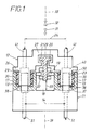
- the device 10 comprises two housings 11, 12, of which the one 12 will hereinafter be referred to as "first housing” for short. It is accommodated by the other housing to be designated as the “second housing”.
- the basic structure of the device 10 is in the coupled state in Fig. 1 in an exploded view of the components in 2, which shows the following special structure:
- the first housing 12 is provided with a plug-in pair 23 in its coupling region 57.
- These plug-in parts 23 are arranged at a lateral distance 24 from one another and in the present case have the profile of approximately rectangular strips 23 which extend over the entire length of the housing 36 and in the present case also have widths 35 which are the same as one another.
- each strip 23 only receives contact members 40 lying in a row 52, which can be seen in FIG. 2, which is why the strips 23 are provided with a set of stepped bores 60.
- the contact members 40 connected to lines 41 here consist of sleeves which move vertically into the bores 60 in the direction of the auxiliary lines 59 shown in FIG. 2 for the purpose of assembly.
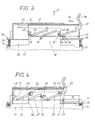
- the bore 60 is widened in the upper region and, in the case of coupling, as shown in FIGS. 6 and 7, receives a sealing plug 62 which surrounds the connected line 41 behind the contact element 40 and seals the bore 60 in a sealed manner in the case of assembly.
- the contact member 40 can have locking tongues 63 which, in the case of installation, engage inside shoulders 64 in the lower, narrowed bore area, which justifies a first securing of the position of the contact members 40 in the plug parts 23.
- a second securing of the position is achieved by locking combs 54 which engage on shoulder surfaces 65 of the contact member 65 and which can be inserted into the plug-in parts 23 in a displaceable manner through slots 53.
- the locking comb 54 has locking cams 58 which, in a pre-locked mounting position according to FIG. 5, lie below the upper partition walls 61 between the bores 60.
- the locking cams 58 are then in alignment with double partitions 66, which are provided in the lower region of the bores 60 and narrow these in their clear width.
- This pre-locking of the comb 54 is achieved by a pre-catch 55 provided on it, which interacts with a housing wall 67 like a snap.
- the contact members can be freely inserted into the bores until, according to FIG. 6, their lower ends come close to the lower end face 38 of the housing legs 23.
- the inlet openings 68 which can be seen in FIG. 6, for the individual contact members 40.
- the locking comb 54 can be moved further by half a distance of its locking cams 58. Then the cams 58 move over the said heel surfaces 65 of the contact member 40 and bring about the aforementioned second securing of these members in the plug-in parts 23. This state can be seen particularly clearly from FIG. 7.
- the fully assembled first housing 12 is now ready to be inserted into the complementary second housing 11, which has the following special structure, in the sense of the insertion direction 31 indicated in FIG. 1.
- the second housing 11 is divided into a corresponding receiving part pair 13. According to the strip profile of the plug-in parts 23, these receiving parts 13 are rectangular and are arranged at a corresponding lateral distance 14 from one another. Each receiving part 13 is delimited by an annular wall 17, a free space 18 shown in FIG. 2 remaining between these annular walls 17.
- a row of counter-contact members 50 positioned in a corresponding arrangement pattern is provided, which are each connected to corresponding electrical lines 51 and which is only shown schematically in FIG. 1.
- the counter-contact members 50 protrude above an inner end face 37 between the ring walls 17.
- These counter-contact members 50 can be positioned in an analogous manner by the latching and securing means described in connection with the second housing 12.
- an outer flange 26 delimiting the coupling region 57 of the plug-in parts 23 comes to rest on a corresponding end face 16 of the receiving wall 17.
- a sealing ring 30 is pushed onto each of the two plug-in parts 23 and comes to one in the case of coupling Inner surface 15 of the receiving wall 17 sealing against the system.
- the members 40, 50 provided on the two end faces 37, 38 of the housings 11, 12 are encapsulated in a moisture-tight manner.
- the control plate 20 is arranged at a lateral distance and in the present case even in a height offset 69 shown in FIG. 1. The latter results in a space-saving construction.
- the control plate 20 comprises a web 21 on its upper longitudinal edge for guiding it and a handle 39 at one end.
- the control plate 20 thus has a T-profile.
- the bridge 27 on the first housing 12 that serves to accommodate it is designed as a complementary T-rail, in which, in the present case, according to FIG. 2, a cavity 70 is provided for moving in the plate area.
- the bridge 27 extends only over part of the length 36 of the plug-in parts 23, which creates a recess 28 in which the handle 39 can be displaced between its extended position according to FIG. 3 and its inserted position according to FIG. 4. In neither of these two positions, the slide 20 thus protrudes laterally beyond the outer boundary of the two housing parts 11, 12 to be coupled.
- the control plate 20 has the following structure and function: Both plate sides 42, 42 'are provided here in a mirror-image arrangement with special control surfaces 22, 22', 43. On its lower longitudinal edge, the control plate 20 has a plurality of latching elements 46, 46 ', 47, each of which cooperates with a wall edge 49 in the bridge region 27 with elastic deformation. After its input assembly, the control plate 20 is in a defined extension position according to FIG. 3, where the two first latching elements 46, 46 'grip the wall edge 29 between them. 3 shows a preassembly position of the first housing 12 equipped with the integrated control plate 20 in the second housing 11.
- the outer flange 26 on its plug parts 23 is still at a height from the end face 16 of the receiving wall 17 belonging to the second housing 11
- Control surfaces already together with special guide members 19, 19 'of the second housing 11, which have the following structure:
- These guide members consist of different cams 19, 19 ' Profiles that protrude into the above-mentioned free space 18 between the two receiving parts 13 and in this way can interact with the control plate 20 movable there.
- the two cams 19 located in the end region of this disk 58 have a half-rounded and half-triangular outline which, in the sectional view of FIG. 3, gives them the profile shape of a "drop".
- the profiling of these two cams 19 is, however, a mirror image of one another. 3 is characterized in that these cams cooperate with complementary angle pieces 43 of the control plate 20. These angle pieces 43 have rounded apex angles 71, according to FIG. 4, in which, in the preassembly position, some of the rounded, some of the angular regions of the cams come to rest.
- the inner latching element 46 ′ runs over the aforementioned wall edge 49 of the bridge 27 and the cams 19 begin to run onto the further control surfaces 22.
- These consist of ribs inclined to the direction of thrust 34, on which the cams 19 move on the upper side.
- the second housing 11 also carries a round pin 19 'which slides along the lower edge of a further central rib 22' along the control plate 20.
- the two housings are finally transferred to the clutch end position shown in FIG. 4.
- this is characterized in that the already mentioned further latching element 47 snaps elastically behind the wall edge 49 and thereby secures the insertion position of the control plate 20.
- the cams 19 are in the upper region of the ribs 22 in a flat 45, which as Locking of the fully engaged housing parts 11, 12 acts. If one tries to pull apart the two housing parts 11, 12 in the locking position 32 in FIG. 1 in this locking position, this remains unsuccessful.
- the ribs 22 are finally provided at their upper end with a butt piece 44 against which the cams 19 abut in this coupling end position of FIG. 4.
- the slide In order to bring about the decoupling 32 of the housing parts 11, 12, the slide must be moved back from its insertion position in FIG. 4 back into the extension position of FIG. 3. Now the middle guide rib 22 'on the control plate 20 is effective.
- the aforementioned round pin 19 'on the second housing 11 moves against its lower edge and exerts a lifting force on the first housing 12, where it begins to move out of the counter-contact members 50 through its contact members 40 until they finally reach the position of FIG 3 disengaged.
- the locking element 47 must of course again be moved forward under deformation on the wall edge 49 until finally the extension position is again defined by the locking elements 46, 46 'placed inwards.
- the two housing parts 11, 12 can now be moved towards one another without any particular effort in the sense of the decoupling arrow 32 from FIG. 1.
- the peculiarity of the invention lies in the fact that the single-walled control plate 20 is arranged in a middle plane 33 between the two pairs of legs and grooves 23, 13 of FIG. 1.
- the control plate 20 is integrated with the first housing 12 and therefore has the associated bearing surfaces 29 there.
- the free space 18 is only required to retract a control plate 20. If there is a sufficient height offset 69, the end faces 16 of the two receiving parts 13 can be more or less flush in the housing and the disks 48 are only required for the guide cams 19, 19 ' to be raised enough.
Landscapes
- Connector Housings Or Holding Contact Members (AREA)
- Coupling Device And Connection With Printed Circuit (AREA)
- Details Of Connecting Devices For Male And Female Coupling (AREA)
- Control Of Motors That Do Not Use Commutators (AREA)
Priority Applications (1)
| Application Number | Priority Date | Filing Date | Title |
|---|---|---|---|
| AT9090105668T ATE104803T1 (de) | 1989-03-29 | 1990-03-26 | Elektrische kupplungsvorrichtung. |
Applications Claiming Priority (2)
| Application Number | Priority Date | Filing Date | Title |
|---|---|---|---|
| DE3910117 | 1989-03-29 | ||
| DE3910117A DE3910117C1 (enExample) | 1989-03-29 | 1989-03-29 |
Publications (2)
| Publication Number | Publication Date |
|---|---|
| EP0390006A1 EP0390006A1 (de) | 1990-10-03 |
| EP0390006B1 true EP0390006B1 (de) | 1994-04-20 |
Family
ID=6377363
Family Applications (1)
| Application Number | Title | Priority Date | Filing Date |
|---|---|---|---|
| EP90105668A Expired - Lifetime EP0390006B1 (de) | 1989-03-29 | 1990-03-26 | Elektrische Kupplungsvorrichtung |
Country Status (4)
| Country | Link |
|---|---|
| EP (1) | EP0390006B1 (enExample) |
| AT (1) | ATE104803T1 (enExample) |
| DE (2) | DE3910117C1 (enExample) |
| ES (1) | ES2056277T3 (enExample) |
Cited By (1)
| Publication number | Priority date | Publication date | Assignee | Title |
|---|---|---|---|---|
| US7517235B2 (en) | 2006-12-28 | 2009-04-14 | General Electric Company | Press fit connection for mounting electrical plug-in outlet insulator to a busway aluminum housing |
Families Citing this family (11)
| Publication number | Priority date | Publication date | Assignee | Title |
|---|---|---|---|---|
| DE9014673U1 (de) * | 1990-10-23 | 1992-02-20 | Grote & Hartmann Gmbh & Co Kg, 5600 Wuppertal | Vielpolige elektrische Steckvorrichtung |
| DE4439673C2 (de) * | 1994-11-07 | 1998-07-23 | Framatome Connectors Int | Leiterplatten-Steckverbinder |
| DE19530335B4 (de) * | 1995-08-17 | 2005-03-24 | The Whitaker Corp., Wilmington | Steckeranordnung |
| DE19626079A1 (de) * | 1996-06-28 | 1998-01-02 | Whitaker Corp | Anordnung zur Sicherung von Kontakten in einem Kontaktgehäuse |
| DE19712831A1 (de) * | 1997-03-26 | 1998-10-01 | Delphi Automotive Systems Gmbh | Modularer Steckverbinder |
| DE19742647A1 (de) * | 1997-09-26 | 1999-04-22 | Siemens Ag | Lösbare elektrische Verbinderanordnung |
| DE29823075U1 (de) * | 1998-12-24 | 2000-05-04 | Grote & Hartmann Gmbh & Co Kg, 42369 Wuppertal | Steckverbindergehäusekupplung |
| DE19933929A1 (de) * | 1999-07-20 | 2001-01-25 | Delphi Tech Inc | Trägersystem |
| DE102007034569B4 (de) * | 2007-07-25 | 2014-12-24 | Bartec Gmbh | Elektrisches Gerät |
| FR3093596B1 (fr) | 2019-03-07 | 2022-04-22 | Aptiv Tech Ltd | Connecteur avec deux directions de déplacement du dispositif pour s’assurer de la position des contacts |
| FR3108203B1 (fr) * | 2020-03-11 | 2023-06-02 | Axon Cable Sa | Ensemble de connexion à fixation rapide et sécurisée |
Family Cites Families (7)
| Publication number | Priority date | Publication date | Assignee | Title |
|---|---|---|---|---|
| US3353143A (en) * | 1965-07-21 | 1967-11-14 | Amp Inc | Electrical connector |
| CA1138973A (en) * | 1978-10-23 | 1983-01-04 | Robert G. Plyler | Weatherproof electric connector |
| FR2455374A1 (fr) * | 1979-04-25 | 1980-11-21 | Cit Alcatel | Dispositif de verrouillage de connecteur |
| US4377319A (en) * | 1981-01-28 | 1983-03-22 | Amp Incorporated | Low insertion force dip connector |
| DE3604548C3 (de) * | 1985-03-04 | 1999-08-19 | Amp Inc | Elektrische Verbinderanordnung mit einem Steuerflächensystem |
| US4684190A (en) * | 1986-03-05 | 1987-08-04 | General Motors Corporation | Sealed electrical connector with shroud |
| US4850890A (en) * | 1987-05-29 | 1989-07-25 | Yazaki Corporation | Multipolar connector |
-
1989
- 1989-03-29 DE DE3910117A patent/DE3910117C1/de not_active Expired - Fee Related
-
1990
- 1990-03-26 EP EP90105668A patent/EP0390006B1/de not_active Expired - Lifetime
- 1990-03-26 ES ES90105668T patent/ES2056277T3/es not_active Expired - Lifetime
- 1990-03-26 DE DE59005402T patent/DE59005402D1/de not_active Expired - Fee Related
- 1990-03-26 AT AT9090105668T patent/ATE104803T1/de not_active IP Right Cessation
Cited By (1)
| Publication number | Priority date | Publication date | Assignee | Title |
|---|---|---|---|---|
| US7517235B2 (en) | 2006-12-28 | 2009-04-14 | General Electric Company | Press fit connection for mounting electrical plug-in outlet insulator to a busway aluminum housing |
Also Published As
| Publication number | Publication date |
|---|---|
| ATE104803T1 (de) | 1994-05-15 |
| ES2056277T3 (es) | 1994-10-01 |
| DE3910117C1 (enExample) | 1990-09-13 |
| EP0390006A1 (de) | 1990-10-03 |
| DE59005402D1 (de) | 1994-05-26 |
Similar Documents
| Publication | Publication Date | Title |
|---|---|---|
| DE3247022C2 (enExample) | ||
| DE4131768B4 (de) | Elektrischer Verbinder mit Doppelverriegelung | |
| DE69421985T2 (de) | Verfahren und Vorrichtung zum doppeltem Sichern eines Anschlusses in einem Verbinder | |
| EP0273999A2 (de) | Verbinderanordnung mit Anhebe-Zahnstange | |
| EP0282622A1 (de) | Steckverbinder zur direkten Kontaktierung einer Leiterplatte | |
| EP1166396A1 (de) | Steckverbindung mit abschirmung | |
| EP0390006B1 (de) | Elektrische Kupplungsvorrichtung | |
| DE3645179C2 (enExample) | ||
| EP0703641B1 (de) | Elektrisches Steckverbindungsteil | |
| DE69215265T3 (de) | Elektrischer Steckverbinder | |
| EP0749180B1 (de) | Steckverbindergehäuse | |
| DE69305021T2 (de) | Elektrischer Verbinder | |
| EP0831561A2 (de) | Elektrische Steckverbinderkupplung | |
| EP1411596A2 (de) | Stecker mit Halteelement | |
| DE69411480T2 (de) | Anschlussleiste | |
| DE4301602C1 (de) | Elektrisches Steckverbindungsteil | |
| DE8914038U1 (de) | Elektrische Kupplungsvorrichtung | |
| EP1411597A2 (de) | Stecker zum Verbinden mit einer Steckbuchse | |
| EP0455972B1 (de) | Vorrichtung zur Unterstützung der gleichzeitigen Herstellung mehrerer parallellaufender fluidischer Steckverbindungen | |
| DE19630754A1 (de) | Einen Halter aufnehmender Steckverbinder | |
| DE3730020C1 (en) | Electrical plug connector coupling | |
| EP0741920B1 (de) | Elektrischer verbindungsteil einer zweiteiligen steckverbindung | |
| DE4016797C2 (de) | Vorrichtung zur hochfrequenzdichten Abschirmung eines Einschub-Gehäuses | |
| DE3604548A1 (de) | Elektrische verbinderanordnung mit einem steuerflaechensystem | |
| DE4034714C2 (de) | Kontaktträger für ein elektromagnetisches Relais |
Legal Events
| Date | Code | Title | Description |
|---|---|---|---|
| PUAI | Public reference made under article 153(3) epc to a published international application that has entered the european phase |
Free format text: ORIGINAL CODE: 0009012 |
|
| 17P | Request for examination filed |
Effective date: 19900720 |
|
| AK | Designated contracting states |
Kind code of ref document: A1 Designated state(s): AT BE DE ES FR GB IT SE |
|
| 17Q | First examination report despatched |
Effective date: 19930910 |
|
| GRAA | (expected) grant |
Free format text: ORIGINAL CODE: 0009210 |
|
| AK | Designated contracting states |
Kind code of ref document: B1 Designated state(s): AT BE DE ES FR GB IT SE |
|
| ITF | It: translation for a ep patent filed | ||
| PG25 | Lapsed in a contracting state [announced via postgrant information from national office to epo] |
Ref country code: SE Free format text: THE PATENT HAS BEEN ANNULLED BY A DECISION OF A NATIONAL AUTHORITY Effective date: 19940420 Ref country code: BE Effective date: 19940420 |
|
| REF | Corresponds to: |
Ref document number: 104803 Country of ref document: AT Date of ref document: 19940515 Kind code of ref document: T |
|
| REF | Corresponds to: |
Ref document number: 59005402 Country of ref document: DE Date of ref document: 19940526 |
|
| GBT | Gb: translation of ep patent filed (gb section 77(6)(a)/1977) |
Effective date: 19940505 |
|
| ET | Fr: translation filed | ||
| REG | Reference to a national code |
Ref country code: ES Ref legal event code: FG2A Ref document number: 2056277 Country of ref document: ES Kind code of ref document: T3 |
|
| PLBE | No opposition filed within time limit |
Free format text: ORIGINAL CODE: 0009261 |
|
| STAA | Information on the status of an ep patent application or granted ep patent |
Free format text: STATUS: NO OPPOSITION FILED WITHIN TIME LIMIT |
|
| PG25 | Lapsed in a contracting state [announced via postgrant information from national office to epo] |
Ref country code: AT Effective date: 19950326 |
|
| 26N | No opposition filed | ||
| REG | Reference to a national code |
Ref country code: FR Ref legal event code: CD |
|
| REG | Reference to a national code |
Ref country code: ES Ref legal event code: PC2A |
|
| PGFP | Annual fee paid to national office [announced via postgrant information from national office to epo] |
Ref country code: GB Payment date: 20000229 Year of fee payment: 11 |
|
| PGFP | Annual fee paid to national office [announced via postgrant information from national office to epo] |
Ref country code: FR Payment date: 20000315 Year of fee payment: 11 |
|
| PGFP | Annual fee paid to national office [announced via postgrant information from national office to epo] |
Ref country code: ES Payment date: 20000327 Year of fee payment: 11 |
|
| PGFP | Annual fee paid to national office [announced via postgrant information from national office to epo] |
Ref country code: DE Payment date: 20000510 Year of fee payment: 11 |
|
| PG25 | Lapsed in a contracting state [announced via postgrant information from national office to epo] |
Ref country code: GB Free format text: LAPSE BECAUSE OF NON-PAYMENT OF DUE FEES Effective date: 20010326 |
|
| PG25 | Lapsed in a contracting state [announced via postgrant information from national office to epo] |
Ref country code: ES Free format text: LAPSE BECAUSE OF NON-PAYMENT OF DUE FEES Effective date: 20010327 |
|
| GBPC | Gb: european patent ceased through non-payment of renewal fee |
Effective date: 20010326 |
|
| PG25 | Lapsed in a contracting state [announced via postgrant information from national office to epo] |
Ref country code: FR Free format text: LAPSE BECAUSE OF NON-PAYMENT OF DUE FEES Effective date: 20011130 |
|
| REG | Reference to a national code |
Ref country code: FR Ref legal event code: ST |
|
| PG25 | Lapsed in a contracting state [announced via postgrant information from national office to epo] |
Ref country code: DE Free format text: LAPSE BECAUSE OF NON-PAYMENT OF DUE FEES Effective date: 20020101 |
|
| REG | Reference to a national code |
Ref country code: ES Ref legal event code: FD2A Effective date: 20030203 |
|
| PG25 | Lapsed in a contracting state [announced via postgrant information from national office to epo] |
Ref country code: IT Free format text: LAPSE BECAUSE OF NON-PAYMENT OF DUE FEES;WARNING: LAPSES OF ITALIAN PATENTS WITH EFFECTIVE DATE BEFORE 2007 MAY HAVE OCCURRED AT ANY TIME BEFORE 2007. THE CORRECT EFFECTIVE DATE MAY BE DIFFERENT FROM THE ONE RECORDED. Effective date: 20050326 |