EP0388585B1 - Connecteur de protection pour barrette de connexion pour technique de télécommunication et de traitement de données - Google Patents
Connecteur de protection pour barrette de connexion pour technique de télécommunication et de traitement de données Download PDFInfo
- Publication number
- EP0388585B1 EP0388585B1 EP90101057A EP90101057A EP0388585B1 EP 0388585 B1 EP0388585 B1 EP 0388585B1 EP 90101057 A EP90101057 A EP 90101057A EP 90101057 A EP90101057 A EP 90101057A EP 0388585 B1 EP0388585 B1 EP 0388585B1
- Authority
- EP
- European Patent Office
- Prior art keywords
- housing
- protection
- circuit board
- terminal
- contact
- Prior art date
- Legal status (The legal status is an assumption and is not a legal conclusion. Google has not performed a legal analysis and makes no representation as to the accuracy of the status listed.)
- Expired - Lifetime
Links
- 238000000034 method Methods 0.000 title claims description 3
- 230000001681 protective effect Effects 0.000 description 38
- 238000006073 displacement reaction Methods 0.000 description 11
- 238000009413 insulation Methods 0.000 description 11
- 239000004020 conductor Substances 0.000 description 8
- 238000010586 diagram Methods 0.000 description 8
- 238000002844 melting Methods 0.000 description 5
- 230000008018 melting Effects 0.000 description 5
- 230000009993 protective function Effects 0.000 description 3
- 239000002184 metal Substances 0.000 description 2
- 230000000284 resting effect Effects 0.000 description 2
- 230000000694 effects Effects 0.000 description 1
- 238000009434 installation Methods 0.000 description 1
- 230000001012 protector Effects 0.000 description 1
Images

Classifications
-
- H—ELECTRICITY
- H01—ELECTRIC ELEMENTS
- H01R—ELECTRICALLY-CONDUCTIVE CONNECTIONS; STRUCTURAL ASSOCIATIONS OF A PLURALITY OF MUTUALLY-INSULATED ELECTRICAL CONNECTING ELEMENTS; COUPLING DEVICES; CURRENT COLLECTORS
- H01R4/00—Electrically-conductive connections between two or more conductive members in direct contact, i.e. touching one another; Means for effecting or maintaining such contact; Electrically-conductive connections having two or more spaced connecting locations for conductors and using contact members penetrating insulation
- H01R4/58—Electrically-conductive connections between two or more conductive members in direct contact, i.e. touching one another; Means for effecting or maintaining such contact; Electrically-conductive connections having two or more spaced connecting locations for conductors and using contact members penetrating insulation characterised by the form or material of the contacting members
- H01R4/66—Connections with the terrestrial mass, e.g. earth plate, earth pin
-
- H—ELECTRICITY
- H01—ELECTRIC ELEMENTS
- H01R—ELECTRICALLY-CONDUCTIVE CONNECTIONS; STRUCTURAL ASSOCIATIONS OF A PLURALITY OF MUTUALLY-INSULATED ELECTRICAL CONNECTING ELEMENTS; COUPLING DEVICES; CURRENT COLLECTORS
- H01R13/00—Details of coupling devices of the kinds covered by groups H01R12/70 or H01R24/00 - H01R33/00
- H01R13/66—Structural association with built-in electrical component
- H01R13/665—Structural association with built-in electrical component with built-in electronic circuit
- H01R13/6666—Structural association with built-in electrical component with built-in electronic circuit with built-in overvoltage protection
-
- H—ELECTRICITY
- H05—ELECTRIC TECHNIQUES NOT OTHERWISE PROVIDED FOR
- H05K—PRINTED CIRCUITS; CASINGS OR CONSTRUCTIONAL DETAILS OF ELECTRIC APPARATUS; MANUFACTURE OF ASSEMBLAGES OF ELECTRICAL COMPONENTS
- H05K1/00—Printed circuits
- H05K1/02—Details
- H05K1/0213—Electrical arrangements not otherwise provided for
- H05K1/0263—High current adaptations, e.g. printed high current conductors or using auxiliary non-printed means; Fine and coarse circuit patterns on one circuit board
-
- H—ELECTRICITY
- H05—ELECTRIC TECHNIQUES NOT OTHERWISE PROVIDED FOR
- H05K—PRINTED CIRCUITS; CASINGS OR CONSTRUCTIONAL DETAILS OF ELECTRIC APPARATUS; MANUFACTURE OF ASSEMBLAGES OF ELECTRICAL COMPONENTS
- H05K1/00—Printed circuits
- H05K1/18—Printed circuits structurally associated with non-printed electric components
-
- Y—GENERAL TAGGING OF NEW TECHNOLOGICAL DEVELOPMENTS; GENERAL TAGGING OF CROSS-SECTIONAL TECHNOLOGIES SPANNING OVER SEVERAL SECTIONS OF THE IPC; TECHNICAL SUBJECTS COVERED BY FORMER USPC CROSS-REFERENCE ART COLLECTIONS [XRACs] AND DIGESTS
- Y10—TECHNICAL SUBJECTS COVERED BY FORMER USPC
- Y10S—TECHNICAL SUBJECTS COVERED BY FORMER USPC CROSS-REFERENCE ART COLLECTIONS [XRACs] AND DIGESTS
- Y10S439/00—Electrical connectors
- Y10S439/922—Telephone switchboard protector
Definitions
- the invention relates to a protective plug for terminal strips of telecommunications and data technology according to the preamble of claim 1.
- a protective plug for connection strips of the generic type is previously known from DE-C-37 26 741.
- insulation displacement contacts are provided in close proximity in two rows, which are used to connect insulated cable wires.
- a protective plug can be inserted from above between the two rows of insulation displacement contacts for each twin wire.
- the protective plug has a tongue which protrudes from the housing and is inserted into a tap which is connected to an insulation displacement contact in each row.
- the earth connection from the surge arrester to an earth rail running outside the terminal block is established by means of a fork contact. Because of the limited space With such an arrangement of closely located protective plugs, only protection against overvoltages is possible.
- the invention is therefore based on the object of providing a protective plug of the generic type in which, in addition to overvoltage protection, current protection is provided without increasing the structural dimensions, in particular the height of the protective plug.
- the circuit board arranged in the housing ensures that protective elements with different protective functions can be used on both sides of the circuit board without the external dimensions, in particular the height, of the protective plug being enlarged. In this way it is achieved that, despite the close-fitting protective plugs and the small installation space within a housing, protection against overvoltages and protection against overcurrents can be formed.
- the cable wires connected to the insulation displacement contacts can be accessed close to tightly arranged protective plugs. Cable wires can also be connected to the insulation displacement contacts using a tool, without the protective plugs still plugged in hindering the tool when it is switched on.
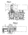
- the protective plug 1 consists of a housing 2, which is formed from two housing halves 3 which are locked together, from a printed circuit board 4 arranged in the housing 2 and forming a plug tongue 5, a voltage limiter 7, two current fuses 8, 9 and an earth contact 40. This is made of plastic
- the housing 2 produced is essentially designed as a cuboid housing body and has two housing openings 16, 17 on its underside 15.
- the slot-shaped housing opening 16 serves to lead through the printed circuit board 4 fixed in the housing 2, the end of which is guided outwards and projects freely from the housing 2 and forms the tongue 5.
- the slot-shaped housing opening 16 is provided approximately in the central region of the underside 15 of the housing 2 has at the slot edge 18 two locking hooks 19, which are provided for locking connection of the protective plug 1 with a terminal block 20.
- the circuit board 4 is also guided and supported between the latching hooks 19 resting on both sides.
- At the other end 52 of the circuit board 4 2 support hooks 45 are provided in the housing, which support and fix the circuit board 4 on both sides.
- the circuit board 4 is thus arranged essentially centrally within the housing 2 and divides the interior of the housing 2 into two housing spaces 21 and 22.
- two power fuses 8, 9 are arranged, which are inserted with their connecting legs 23, 24 into connection points A, F and C, E.
- a voltage limiter 7 is arranged in the second housing space 22 and is inserted with its connecting legs 25, 26 into the connecting points B, D of the printed circuit board 4. Since the power fuses 8, 9 have their two connecting legs 23, 24 on two opposite side faces 28, the connecting legs 23 of the power fuses 8, 9 are longer and are bent twice by 90 °, so that the ends of all the connecting legs 23, 24 of the power fuses 8, 9 point in the same direction.
- a so-called solid-state protector for example a so-called solid-state protector, consists of a plate-shaped housing body and has three connection legs 25, 26, 27 on one side of the housing, which are in a row are arranged.
- the middle connection leg 27 is shortened so that there is a distance a between the end of the connection leg 27 and the printed circuit board 4, as is shown in particular in FIG.
- a metallic clamp 30 is attached as thermal protection over the voltage limiter 7.
- the bracket 30 is in cross section in essentially U-shaped and has lateral sheet metal tabs 29 which are bent by 90 ° and bear against the side surfaces 31 of the voltage limiter 7.
- the legs 32, 33 of the U-shaped bracket 30 rest on the front and rear sides 34, 35 of the voltage limiter 7.
- the ends of the legs 32, 33 are bent through approximately 90 ° and form resilient contact elements 37, 38, which are used for connection to the connecting legs 25, 26, 27.
- the leg 33 resting on the rear side 35 is trapezoidal, so that the resilient contact element 38 is in contact with the central connecting leg 27 without touching the connecting legs 25, 26.
- the leg 32 of the clamp 30, on the other hand, is held at a distance from the front side 34 by a melting element 36 fastened to it, so that the contact elements 37 are also at a distance from the connecting legs 25, 26.
- a contact tongue 39 is provided on the clamp 30 and is inserted into a fork contact 41 of the earth contact 40.
- the earth contact 40 consists of a metallic sheet metal strip, at the ends of which a fork contact 41, 42 is formed.
- the fork contact 41 is arranged inside and the fork contact 42 outside the housing 2, the earth contact 40 being received and held in the slot-shaped housing opening 17.
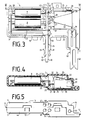
- first circuit board 4 For different protective functions, either a first circuit board 4 or a second circuit board 4a is inserted into the housing 2. Both circuit boards 4,4a have the same connection points A to F. However, they differ in other printed images of the conductor tracks.
- the circuit board 4 is shown in FIGS. 6 and 7, the associated circuit diagram in FIG. 10.
- the circuit board 4a is shown in FIGS. 8 and 9, the associated circuit diagram in FIG. 11.
- the printed circuit board 4 according to FIGS. 6, 7, 10 In order to use the current protection against the overvoltage protection (securing the line side), the printed circuit board 4 according to FIGS. 6, 7, 10 must be used. 10 shows on the left the line-side connections a and b of the cable cores and on the right the office-side connections a 'and b'. Furthermore, the circuit diagram shows that the power fuse 8 is connected to the connection points E and C and the power fuse 9 is connected to the connection points A and F. The voltage limiter 7 is connected to the connection points D and B. In this circuit diagram, the a-wire is connected to connection point E, the b-wire to connection point F, the a'-wire to connection point D and the b'-wire to connection point B.
- the printed circuit board 4a according to FIGS. 8, 9 and 11 must be used.
- the line-side connections a and b are shown on the left and the office-side connections a ', b' for the cable cores are shown on the right.
- the power fuse 8 is connected to the connection points C and E and the power fuse 9 is connected to the connection points A and F.
- the current limiter 7 is also connected to the connection points B and D.
- the cable wire a at the connection point D, the cable wire b at the connection point B, the cable wire a 'at the connection point E and the cable wire b' at the connection point F are connected to the circuit board 4a.
- the protective plug 1 is inserted to discharge overvoltages and to protect against overcurrents between the cable wires a, b and a ', b' in the isolating contact 43 of a terminal block 20.
- work contacts (not shown) can also be inserted into the terminal block 20.
- the terminal block 20 has two rows of insulation displacement contacts 42, two opposing insulation displacement contacts 53 being connected by the isolating contact 43 and being separated by inserting the protective plug 1.
- an earth rail 44 is arranged, which is arranged longitudinally next to the terminal block 20.
- the protective plug 1 is inserted in the center of the terminal block 20 from above, the tongue 5 of the protective plug 1 being inserted into the isolating contact 43.
- the conductor tracks 10 arranged on both sides of the tongue 5 are thus electrically connected to the isolating contact 43.
- the tongue 5 has two adjacent conductor tracks 10 on each side, so that a double wire a, b is protected by a protective plug 1.
- the fork contact 42 of the earth contact 40 of the protective plug 1 is also connected to the earth rail 44, since the earth rail 44 is inserted into the fork contact 42.
- the overvoltage case is explained in more detail below with the aid of the figures.
- the current flows from the cable core a via the insulation displacement contact 53 to the isolating contact 43 and via the conductor tracks 10 of the tongue 5 to the connection point E when the printed circuit board 4 according to FIG. 10 is inserted. From the connection point E, the current flows through the connection leg 23, through the current fuse 8, through the connection leg 24 to the connection point C.
- connection point C From the connection point C via the conductor track 10 to the connection point D, to which the connection leg 26 of the voltage limiter 7 is connected.
- the current now flows through the voltage limiter 7 to the connecting leg 27 and from there via the clamp 33 and the contact tongue 39 to the earth contact 40, the fork contact 42 of which is electrically connected to the earth rail 44.
- the current is conducted to earth via earth rail 44.
- the current flow works in a similar manner via the insulation displacement contact 53 to the isolating contact 43, via the conductor 10 of the tongue 5 to the connection point F, through the power fuse 9 to the connection point A, via the conductor 10 to the connection point B, the is connected to the connecting leg 25 of the voltage limiter 7.
- the current flows through the voltage limiter 7 to the connecting leg 27 and from there via the clamp 33 and the contact tongue 39 to the earth contact 40 and to the earth rail 44.
- the second circuit board 4a in which the current protection is arranged on the official side, then the current flow of the power fuses 8.9 interrupted at high currents and at low voltages; in this case the voltage limiter 7 does not respond.
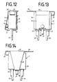
- the housing 2 of the protective plug 1 is provided with cutouts 13 on both sides on one narrow side 11 and with step-shaped clearances 14 on the other narrow side 12.
- the cutouts 13 After a protective plug 1 has been pulled out of a number of a plurality of protective plugs 1 arranged closely next to one another, the cable wires a, b connected to the insulation displacement contacts 53 are accessible.
- the available space 6 by pulling the protective plug 1 is so large that a tool, not shown, can connect the cable wires from without hindrance.
- the step-shaped clearances 14 achieve a space-saving arrangement of two protective plugs 1 inserted in opposite directions in the terminal block 20.
- a total of five housing openings 47 to 51 are provided, which are used to insert a test tip (not shown) of a test plug.
- the housing opening 47 serves as an access for the a-core
- the housing opening 48 for the a'-core the housing opening 49 for the b-core
- the housing opening 50 for the b'-core the housing opening 51 serves as access to the earth potential.
Landscapes
- Engineering & Computer Science (AREA)
- Microelectronics & Electronic Packaging (AREA)
- Details Of Connecting Devices For Male And Female Coupling (AREA)
- Coupling Device And Connection With Printed Circuit (AREA)
- Emergency Protection Circuit Devices (AREA)
- Structure Of Telephone Exchanges (AREA)
- Connections Arranged To Contact A Plurality Of Conductors (AREA)
Claims (7)
- Connecteur de protection pour barrette de connexion pour technique de télécommunication et de traitement de données, comprenant un boîtier (2) pour recevoir des éléments de protection qui sont raccordés à un contact à fourche (42) ou à des pistes conductives (10) prévues sur une lame de contact (5) pour la connexion électrique à un rail de mise à la terre (44) et à un contact de séparation (43), le contact de travail étant connecté avec des contacts de connexion (53) pour les connecteurs de câble d'éntrée et de sortie,
caractérisé en ce que la lame de contact (5) est formée d'une carte imprimée (4, 4a), qui s'étend dans le boîtier (2), de sorte que deux espaces de boîtier (21, 22) soient formés au-dedans du boîtier (2),
qu'au-dedans des espaces de boîtier (21, 22) sont disposés des éléments de protection (7, 8, 9) de part et d'autre de la carte imprimée (4, 4a), et
que les éléments de protection (7, 8, 9) sont connectés l'un à l'autre par l'intermédiaire des pistes conductives (10) et par l'intermédiaire de terminaux (A à F) à trous métallisés. - Connecteur de protection selon la revendication 1,
caractérisé en ce que dans le premier espace (21) est disposé au moins un dispositif de protection contre les surcourants (8, 9) et dans le deuxième espace de boîtier (22) un limiteur de tension (7). - Connecteur de protection selon la revendication 1,
caractérisé en ce que les éléments de protection (7, 8, 9) sont électrique connectés avec les terminaux (A à F). - Connecteur de protection la revendication 1,
caractérisé en ce que le premier terminal (A) est connecté avec le deuxième terminal (B) et le troisième terminal (C) avec le quatrième terminal (D) par l'intermédiaire des pistes conductives (10). - Connecteur de protection selon les revendications 2 et 4,
caractérisé en ce que lors d'une première carte imprimée (4) un premier dispositif de protection contre les surcourants (8) est connecté avec le troisième et cinquième terminal (C, E) et un deuxième dispositif de protection contre les surcourants (9) avec le premier et sixième terminal (A, F) et le limiteur de tension (7) avec le deuxième et quatrième terminal (B, D). - Connecteur de protection selon les revendications 2 et 4,
caractérisé en ce que lors d'une deuxième carte imprimée (4a) un premier dispositif de protection contre les surcourants (8) est connecté avec le troisième et cinquième terminal (C, E) et un deuxième dispositif de protection contre les surcourants (9) avec le premier et sixième terminal (A, F) et le limiteur de tension (7) avec le deuxième et quatrième terminal (B, D). - Connecteur de protection selon la revendication 1,
caractérisé en ce que le boîtier (2) est prévu à un petit côté (11) de part de d'autre d'évidements (13) et à l'autre petit côté (12) de découpures à étapes (14).
Applications Claiming Priority (2)
| Application Number | Priority Date | Filing Date | Title |
|---|---|---|---|
| DE3909783 | 1989-03-22 | ||
| DE3909783A DE3909783C2 (de) | 1989-03-22 | 1989-03-22 | Schutzstecker für Anschlußleisten der Fernmelde- und Datentechnik |
Publications (3)
| Publication Number | Publication Date |
|---|---|
| EP0388585A2 EP0388585A2 (fr) | 1990-09-26 |
| EP0388585A3 EP0388585A3 (fr) | 1991-08-21 |
| EP0388585B1 true EP0388585B1 (fr) | 1994-12-21 |
Family
ID=6377153
Family Applications (1)
| Application Number | Title | Priority Date | Filing Date |
|---|---|---|---|
| EP90101057A Expired - Lifetime EP0388585B1 (fr) | 1989-03-22 | 1990-01-19 | Connecteur de protection pour barrette de connexion pour technique de télécommunication et de traitement de données |
Country Status (9)
| Country | Link |
|---|---|
| US (1) | US5157580A (fr) |
| EP (1) | EP0388585B1 (fr) |
| AR (1) | AR242875A1 (fr) |
| AT (1) | ATE116076T1 (fr) |
| AU (2) | AU628483B2 (fr) |
| CA (1) | CA2012870C (fr) |
| DE (2) | DE3909783C2 (fr) |
| DK (1) | DK0388585T3 (fr) |
| ES (1) | ES2065414T3 (fr) |
Families Citing this family (45)
| Publication number | Priority date | Publication date | Assignee | Title |
|---|---|---|---|---|
| DE8908236U1 (de) * | 1989-07-06 | 1989-08-31 | "Telegärtner" Karl Gärtner, 71144 Steinenbronn | Anschlußeinrichtung für ein Datennetz |
| US5247273A (en) * | 1991-03-22 | 1993-09-21 | Mitsubishi Materials Corporation | Surge absorber for protection of communication equipment connected to communication lines |
| US5359657A (en) * | 1992-06-08 | 1994-10-25 | Oneac Corporation | Telephone line overvoltage protection apparatus |
| US5451170A (en) * | 1993-09-28 | 1995-09-19 | Reliance Comm/Tec Corporation | Terminal block with protection |
| DE69402671T2 (de) * | 1993-12-10 | 1997-07-31 | Texas Instruments Inc | Betriebssichere Vorrichtung zur Anwendung in elektrischen Überspannungsableiter |
| FR2714221B1 (fr) * | 1993-12-21 | 1997-01-24 | Pontarlier Connectors | Elément de contact comportant un corps conducteur allongé et ensemble de connexion le comprenant. |
| DE4402365A1 (de) * | 1994-01-27 | 1995-08-03 | Deutsche Bundespost Telekom | Leitungsstecker für die Vorbereitung und Durchführung von Umschaltmaßnahmen an Verteilern |
| US5587884A (en) * | 1995-02-06 | 1996-12-24 | The Whitaker Corporation | Electrical connector jack with encapsulated signal conditioning components |
| WO1996024968A1 (fr) * | 1995-02-06 | 1996-08-15 | The Whitaker Corporation | Ensemble prise pour connecteurs electriques utilise dans la transmission de signaux |
| US5549489A (en) * | 1995-05-17 | 1996-08-27 | Lucent Technologies Inc. | Connector module with test and jumper access |
| US5575689A (en) * | 1995-05-17 | 1996-11-19 | Lucent Technologies Inc. | Connector modules |
| US5596475A (en) * | 1995-06-30 | 1997-01-21 | Lucent Technologies Inc. | Protector device |
| US5718593A (en) * | 1995-07-03 | 1998-02-17 | Lucent Technologies Inc. | Polarity-sensitive protector device |
| DE19608517C2 (de) * | 1996-03-05 | 2000-11-09 | Quante Ag | Anschlußmodul für die Telekommunikationstechnik |
| US5844785A (en) * | 1996-07-31 | 1998-12-01 | Lucent Technologies Inc. | Protector device with isolated ground connector |
| DE19722936C1 (de) * | 1997-05-23 | 1998-10-08 | Krone Ag | Schutzstecker |
| DE19722580C1 (de) * | 1997-05-30 | 1998-10-15 | Krone Ag | Überspannungsschutzstecker mit Fail-Safe |
| DE29805313U1 (de) | 1998-03-17 | 1998-06-10 | Elmeg Gmbh Kommunikationstechnik, 31228 Peine | Telekommunikationsanlage |
| DE19816907B4 (de) * | 1998-04-16 | 2006-09-28 | Quante Ag | Schutzstecker für eine Einrichtung der Telekommunikationstechnik |
| US6317307B1 (en) * | 1998-10-07 | 2001-11-13 | Siecor Operations, Llc | Coaxial fuse and protector |
| DE19900759A1 (de) | 1999-01-12 | 2000-07-27 | Krone Ag | Überspannungsableitermagazin für die Telekommunikations- und Datentechnik |
| DE29909701U1 (de) * | 1999-06-02 | 1999-09-09 | Quante Ag, 42109 Wuppertal | Schutzstecker für eine Einrichtung der Telekommunikationstechnik |
| DE29920935U1 (de) * | 1999-11-29 | 2000-02-03 | Quante Ag, 42109 Wuppertal | Überspannungsschutzmagazin |
| DE20002378U1 (de) | 2000-02-11 | 2000-04-27 | Quante Ag, 42109 Wuppertal | Schutzmodul der Telekommunikationstechnik |
| DE10029649C9 (de) | 2000-06-15 | 2008-02-07 | Adc Gmbh | Verteileranschlußmodul für die Telekommunikations- und Datentechnik |
| US6532066B1 (en) | 2000-08-05 | 2003-03-11 | Ford Global Technologies, Inc. | Vision system for identification of defects in wet polymeric coatings |
| US7155004B1 (en) * | 2002-11-22 | 2006-12-26 | Adc Incorporated | System and method of delivering DSL services |
| US7409053B1 (en) | 2002-11-22 | 2008-08-05 | Adc Telecommunications, Inc. | System and method of providing DSL services on a telephone network |
| EP1455417A1 (fr) * | 2003-03-03 | 2004-09-08 | 3M Innovative Properties Company | Module fonctionnel pour montage dans un module de télécommunication et méthode d'installation du module de télécommunication |
| EP1455543B1 (fr) * | 2003-03-03 | 2011-01-05 | 3M Innovative Properties Company | Dispositif de modules de télécommunication ayant au moins une fiche de protection |
| US7643631B2 (en) * | 2005-08-26 | 2010-01-05 | Adc Telecommunications, Inc. | Enclosure for broadband service delivery system |
| US7522721B2 (en) * | 2005-08-26 | 2009-04-21 | Adc Telecommunications, Inc. | System for broadband service delivery |
| US20070047526A1 (en) * | 2005-08-26 | 2007-03-01 | Bryan Kennedy | Systems and methods for conecting between telecommunications equipment |
| DE102005042163B3 (de) | 2005-09-06 | 2007-03-22 | Adc Gmbh | Schutzstecker für ein Anschlussmodul |
| US7466529B2 (en) * | 2005-09-09 | 2008-12-16 | Jae-Han Joung | Communication-circuit line protector |
| US8064182B2 (en) | 2007-02-28 | 2011-11-22 | Adc Telecommunications, Inc. | Overvoltage protection plug |
| DE102007026097B4 (de) * | 2007-06-05 | 2023-05-11 | Tyco Electronics Services Gmbh | Steckverbinder für Leiterplatten |
| DE102007026096A1 (de) * | 2007-06-05 | 2008-12-11 | Adc Gmbh | Aderanschlussmodul |
| DE102007026094B4 (de) * | 2007-06-05 | 2023-05-11 | Tyco Electronics Services Gmbh | Kontaktelement für einen Steckverbinder für Leiterplatten |
| DE102007026102B3 (de) * | 2007-06-05 | 2008-11-13 | Adc Gmbh | Steckverbinder für Leiterplatten |
| DE102007026095A1 (de) * | 2007-06-05 | 2008-12-11 | Adc Gmbh | Erdkamm, insbesondere für einen Steckverbinder für Leiterplatten |
| US7946863B2 (en) * | 2008-04-25 | 2011-05-24 | Adc Telecommunications, Inc. | Circuit protection block |
| US8411404B2 (en) * | 2008-05-27 | 2013-04-02 | Adc Telecommunications, Inc. | Overvoltage protection plug |
| DE102016116926A1 (de) * | 2016-09-09 | 2018-03-15 | Harting Electric Gmbh & Co. Kg | Überspannungsschutzmodul für einen modularen Steckverbinder |
| DE102019112951B3 (de) * | 2019-05-16 | 2020-09-17 | Dehn Se + Co Kg | System zum Schutz einer elektrischen Quelle oder elektrischen Last |
Family Cites Families (20)
| Publication number | Priority date | Publication date | Assignee | Title |
|---|---|---|---|---|
| DE1249935B (fr) * | 1962-07-24 | 1967-09-14 | ||
| DE2032994B2 (de) * | 1970-07-03 | 1972-07-27 | Licentia Patent-Verwaltungs-Gmbh, 6000 Frankfurt | Anordnung zum einbau und verdrahten von ueberspannungsableitern in geraeten und anlagen der nachrichtentechnik, insbesondere in garnituren und endgestellen von fernmeldekabelanlagen |
| FR2341974A1 (fr) * | 1976-02-18 | 1977-09-16 | Causse Raoul | Dispositif de protection de lignes basse tension, notamment pour reseau telephonique |
| US4113340A (en) * | 1977-06-27 | 1978-09-12 | Illinois Tool Works Inc. | Protective electrical device |
| DE3032456A1 (de) * | 1980-08-28 | 1982-04-01 | Siemens AG, 1000 Berlin und 8000 München | Sicherungsleiste zur halterung elektrischer schutzelemente |
| DE3323687C2 (de) * | 1983-07-01 | 1986-12-18 | Krone Gmbh, 1000 Berlin | Überspannungsableitermagazin für Anschlußleisten der Fernmeldetechnik |
| DE3412452A1 (de) * | 1984-04-03 | 1985-10-10 | Siemens AG, 1000 Berlin und 8000 München | Schutzstecker fuer verteilerleisten |
| DE3440748C2 (de) * | 1984-11-08 | 1993-12-23 | Hirschmann Richard Gmbh Co | Leitungssteckverbinder mit Bauelementeeinsatz |
| NZ216143A (en) * | 1985-06-03 | 1989-04-26 | Adc Telecommunications Inc | Distribution frame wire connection module with insertable overvoltage protector |
| DE3674095D1 (de) * | 1985-07-15 | 1990-10-18 | Siemens Ag | Steckbare baugruppe mit elektrischen sicherungselementen fuer verteiler. |
| DE3621200A1 (de) * | 1986-06-25 | 1988-01-07 | Siemens Ag | Schutzbaustein fuer telekommunikationsanlagen |
| US4649456A (en) * | 1986-06-30 | 1987-03-10 | Porta Systems Corp. | Three element gas tube protector module |
| US4866560A (en) * | 1988-04-22 | 1989-09-12 | Allina Edward F | Safeguarding electrical transient surge protection |
| DE3644349C1 (de) * | 1986-12-19 | 1988-02-25 | Krone Ag | Anschlussleiste fuer die Fernmeldetechnik |
| DE3727568A1 (de) * | 1987-03-25 | 1989-02-23 | Krone Ag | Schutzstecker fuer schalt- oder trennleisten der fernmeldetechnik |
| AU607224B2 (en) * | 1987-06-05 | 1991-02-28 | Krone Aktiengesellschaft | Electrical device |
| DE3726741C1 (de) * | 1987-08-07 | 1988-09-01 | Krone Ag | Anschlussleiste der Fernmeldetechnik |
| DE3730662A1 (de) * | 1987-09-10 | 1989-03-30 | Krone Ag | Anschlussvorrichtung der fernmeldetechnik |
| US4856060A (en) * | 1988-08-01 | 1989-08-08 | Porta Systems Corp. | Solid state telephone protector module |
| DE3840198A1 (de) * | 1988-11-29 | 1990-05-31 | Dehn & Soehne | Steckdose mit ueberspannungsschutz |
-
1989
- 1989-03-22 DE DE3909783A patent/DE3909783C2/de not_active Expired - Fee Related
-
1990
- 1990-01-19 ES ES90101057T patent/ES2065414T3/es not_active Expired - Lifetime
- 1990-01-19 DK DK90101057.9T patent/DK0388585T3/da active
- 1990-01-19 AT AT90101057T patent/ATE116076T1/de active
- 1990-01-19 DE DE59008050T patent/DE59008050D1/de not_active Expired - Fee Related
- 1990-01-19 EP EP90101057A patent/EP0388585B1/fr not_active Expired - Lifetime
- 1990-03-05 AU AU50677/90A patent/AU628483B2/en not_active Ceased
- 1990-03-16 US US07/495,793 patent/US5157580A/en not_active Expired - Fee Related
- 1990-03-19 AR AR90316404A patent/AR242875A1/es active
- 1990-03-22 CA CA002012870A patent/CA2012870C/fr not_active Expired - Fee Related
-
1992
- 1992-07-16 AU AU20354/92A patent/AU649853B2/en not_active Ceased
Also Published As
| Publication number | Publication date |
|---|---|
| DE59008050D1 (de) | 1995-02-02 |
| ES2065414T3 (es) | 1995-02-16 |
| CA2012870A1 (fr) | 1990-09-22 |
| AU2035492A (en) | 1992-09-17 |
| AU649853B2 (en) | 1994-06-02 |
| DK0388585T3 (da) | 1995-02-27 |
| DE3909783C2 (de) | 1996-06-13 |
| AU628483B2 (en) | 1992-09-17 |
| AU5067790A (en) | 1990-09-27 |
| EP0388585A2 (fr) | 1990-09-26 |
| EP0388585A3 (fr) | 1991-08-21 |
| ATE116076T1 (de) | 1995-01-15 |
| US5157580A (en) | 1992-10-20 |
| DE3909783C1 (fr) | 1990-10-18 |
| AR242875A1 (es) | 1993-05-31 |
| CA2012870C (fr) | 1996-03-05 |
Similar Documents
| Publication | Publication Date | Title |
|---|---|---|
| EP0388585B1 (fr) | Connecteur de protection pour barrette de connexion pour technique de télécommunication et de traitement de données | |
| DE102005042163B3 (de) | Schutzstecker für ein Anschlussmodul | |
| DE10029649C5 (de) | Verteileranschlußmodul für die Telekommunikations- und Datentechnik | |
| DE3687321T2 (de) | Modulares verteilergestell mit schutzmoduln, die durch auftrennung des stromkreises getestet werden koennen. | |
| DE3137429A1 (de) | Vorrichtung zur herstellung eines loet,- schraub- undabisolierfreien einfach- oder mehrfachkontaktes an einem anschlusselement | |
| DE2706681A1 (de) | Schutzeinrichtung fuer niederspannungsleitungen, insbesondere fuer fernsprechnetze | |
| DE69619033T2 (de) | Polaritätsempfindliche Schutzvorrichtung | |
| EP0477664B1 (fr) | Insert de protection pour réglette à bornes installée dans un équipement de télécommunication, en particulier dans un poste annexe téléphonique | |
| DE69020154T2 (de) | Überlastungsschutz für fernmeldesysteme. | |
| DE2315838A1 (de) | Sicherungsleiste mit einer anzahl von elektrischen sicherungen | |
| EP0952635B1 (fr) | Connecteur électrique | |
| DE102014116811A1 (de) | Reihenklemme | |
| EP0765091A2 (fr) | Réglette de connexion multiple de module pour raccords de câbles d'un répartiteur principal de lignes téléphoniques et de données | |
| EP0890205B1 (fr) | Dispositif de distribution d'un distributeur dans un systeme de telecommunications | |
| EP0990280B1 (fr) | Connecteur de protection pour dispositif utilise dans la technique des telecommunications | |
| DE3412421A1 (de) | Schutzelement fuer verteilerleisten | |
| DD297286A5 (de) | Schutzeinrichtung fuer einen verteiler in einer telekommunikationsanlage | |
| WO2010043356A1 (fr) | Module de raccordement | |
| DE4114947C1 (en) | Protective plug for coupling to distributor contact module - has two differently shaped contact faces for contact spring of spring pair | |
| DE3625422C2 (fr) | ||
| EP1059703B1 (fr) | Fiche de protection pour un dispositif de la technique de télécommunication | |
| DE2643088A1 (de) | Verteileranordnung fuer fernmeldevermittlungsanlagen | |
| EP0660458A2 (fr) | Dispositifs de raccordement pour lignes de télécommunications / données | |
| DE2238515C3 (de) | Schaltverteiler für Fernmelde-, insbesondere Fernsprechanlagen | |
| DE9411457U1 (de) | Elektrische Anschlußklemme |
Legal Events
| Date | Code | Title | Description |
|---|---|---|---|
| PUAI | Public reference made under article 153(3) epc to a published international application that has entered the european phase |
Free format text: ORIGINAL CODE: 0009012 |
|
| AK | Designated contracting states |
Kind code of ref document: A2 Designated state(s): AT BE CH DE DK ES FR GB GR IT LI LU NL SE |
|
| PUAL | Search report despatched |
Free format text: ORIGINAL CODE: 0009013 |
|
| AK | Designated contracting states |
Kind code of ref document: A3 Designated state(s): AT BE CH DE DK ES FR GB GR IT LI LU NL SE |
|
| 17P | Request for examination filed |
Effective date: 19910710 |
|
| 17Q | First examination report despatched |
Effective date: 19940204 |
|
| GRAA | (expected) grant |
Free format text: ORIGINAL CODE: 0009210 |
|
| AK | Designated contracting states |
Kind code of ref document: B1 Designated state(s): AT BE CH DE DK ES FR GB GR IT LI LU NL SE |
|
| REF | Corresponds to: |
Ref document number: 116076 Country of ref document: AT Date of ref document: 19950115 Kind code of ref document: T |
|
| ITF | It: translation for a ep patent filed | ||
| ET | Fr: translation filed | ||
| EAL | Se: european patent in force in sweden |
Ref document number: 90101057.9 |
|
| REF | Corresponds to: |
Ref document number: 59008050 Country of ref document: DE Date of ref document: 19950202 |
|
| GBT | Gb: translation of ep patent filed (gb section 77(6)(a)/1977) |
Effective date: 19950112 |
|
| REG | Reference to a national code |
Ref country code: ES Ref legal event code: FG2A Ref document number: 2065414 Country of ref document: ES Kind code of ref document: T3 |
|
| REG | Reference to a national code |
Ref country code: DK Ref legal event code: T3 |
|
| REG | Reference to a national code |
Ref country code: GR Ref legal event code: FG4A Free format text: 3014765 |
|
| PLBE | No opposition filed within time limit |
Free format text: ORIGINAL CODE: 0009261 |
|
| STAA | Information on the status of an ep patent application or granted ep patent |
Free format text: STATUS: NO OPPOSITION FILED WITHIN TIME LIMIT |
|
| 26N | No opposition filed | ||
| PGFP | Annual fee paid to national office [announced via postgrant information from national office to epo] |
Ref country code: DE Payment date: 19980130 Year of fee payment: 9 |
|
| PGFP | Annual fee paid to national office [announced via postgrant information from national office to epo] |
Ref country code: GB Payment date: 19981216 Year of fee payment: 10 |
|
| PGFP | Annual fee paid to national office [announced via postgrant information from national office to epo] |
Ref country code: ES Payment date: 19990118 Year of fee payment: 10 |
|
| PGFP | Annual fee paid to national office [announced via postgrant information from national office to epo] |
Ref country code: FR Payment date: 19990121 Year of fee payment: 10 |
|
| PGFP | Annual fee paid to national office [announced via postgrant information from national office to epo] |
Ref country code: SE Payment date: 19990126 Year of fee payment: 10 Ref country code: DK Payment date: 19990126 Year of fee payment: 10 |
|
| PGFP | Annual fee paid to national office [announced via postgrant information from national office to epo] |
Ref country code: AT Payment date: 19990127 Year of fee payment: 10 |
|
| PGFP | Annual fee paid to national office [announced via postgrant information from national office to epo] |
Ref country code: NL Payment date: 19990128 Year of fee payment: 10 Ref country code: CH Payment date: 19990128 Year of fee payment: 10 Ref country code: BE Payment date: 19990128 Year of fee payment: 10 |
|
| PGFP | Annual fee paid to national office [announced via postgrant information from national office to epo] |
Ref country code: LU Payment date: 19990129 Year of fee payment: 10 Ref country code: GR Payment date: 19990129 Year of fee payment: 10 |
|
| PG25 | Lapsed in a contracting state [announced via postgrant information from national office to epo] |
Ref country code: DE Free format text: LAPSE BECAUSE OF NON-PAYMENT OF DUE FEES Effective date: 19991103 |
|
| PG25 | Lapsed in a contracting state [announced via postgrant information from national office to epo] |
Ref country code: LU Free format text: LAPSE BECAUSE OF NON-PAYMENT OF DUE FEES Effective date: 20000119 Ref country code: GB Free format text: LAPSE BECAUSE OF NON-PAYMENT OF DUE FEES Effective date: 20000119 Ref country code: DK Free format text: LAPSE BECAUSE OF NON-PAYMENT OF DUE FEES Effective date: 20000119 Ref country code: AT Free format text: LAPSE BECAUSE OF NON-PAYMENT OF DUE FEES Effective date: 20000119 |
|
| PG25 | Lapsed in a contracting state [announced via postgrant information from national office to epo] |
Ref country code: SE Free format text: LAPSE BECAUSE OF NON-PAYMENT OF DUE FEES Effective date: 20000120 Ref country code: ES Free format text: THE PATENT HAS BEEN ANNULLED BY A DECISION OF A NATIONAL AUTHORITY Effective date: 20000120 |
|
| PG25 | Lapsed in a contracting state [announced via postgrant information from national office to epo] |
Ref country code: LI Free format text: LAPSE BECAUSE OF NON-PAYMENT OF DUE FEES Effective date: 20000131 Ref country code: GR Free format text: LAPSE BECAUSE OF NON-PAYMENT OF DUE FEES Effective date: 20000131 Ref country code: CH Free format text: LAPSE BECAUSE OF NON-PAYMENT OF DUE FEES Effective date: 20000131 Ref country code: BE Free format text: LAPSE BECAUSE OF NON-PAYMENT OF DUE FEES Effective date: 20000131 |
|
| BERE | Be: lapsed |
Owner name: KRONE A.G. Effective date: 20000131 |
|
| PG25 | Lapsed in a contracting state [announced via postgrant information from national office to epo] |
Ref country code: NL Free format text: LAPSE BECAUSE OF NON-PAYMENT OF DUE FEES Effective date: 20000801 |
|
| GBPC | Gb: european patent ceased through non-payment of renewal fee |
Effective date: 20000119 |
|
| EUG | Se: european patent has lapsed |
Ref document number: 90101057.9 |
|
| REG | Reference to a national code |
Ref country code: CH Ref legal event code: PL |
|
| PG25 | Lapsed in a contracting state [announced via postgrant information from national office to epo] |
Ref country code: FR Free format text: LAPSE BECAUSE OF NON-PAYMENT OF DUE FEES Effective date: 20000929 |
|
| NLV4 | Nl: lapsed or anulled due to non-payment of the annual fee |
Effective date: 20000801 |
|
| REG | Reference to a national code |
Ref country code: DK Ref legal event code: EBP |
|
| REG | Reference to a national code |
Ref country code: FR Ref legal event code: ST |
|
| REG | Reference to a national code |
Ref country code: ES Ref legal event code: FD2A Effective date: 20020204 |
|
| PG25 | Lapsed in a contracting state [announced via postgrant information from national office to epo] |
Ref country code: IT Free format text: LAPSE BECAUSE OF NON-PAYMENT OF DUE FEES Effective date: 20050119 |