EP0386500B1 - Auswechselkassette für ein Handgerät zum Übertragen eines Filmes von einem Trägerband auf ein Substrat - Google Patents
Auswechselkassette für ein Handgerät zum Übertragen eines Filmes von einem Trägerband auf ein Substrat Download PDFInfo
- Publication number
- EP0386500B1 EP0386500B1 EP90102941A EP90102941A EP0386500B1 EP 0386500 B1 EP0386500 B1 EP 0386500B1 EP 90102941 A EP90102941 A EP 90102941A EP 90102941 A EP90102941 A EP 90102941A EP 0386500 B1 EP0386500 B1 EP 0386500B1
- Authority
- EP
- European Patent Office
- Prior art keywords
- cassette
- transverse rib
- spool
- exchangeable
- cassette according
- Prior art date
- Legal status (The legal status is an assumption and is not a legal conclusion. Google has not performed a legal analysis and makes no representation as to the accuracy of the status listed.)
- Expired - Lifetime
Links
- 210000002105 tongue Anatomy 0.000 claims description 45
- 239000004033 plastic Substances 0.000 claims description 11
- 229920003023 plastic Polymers 0.000 claims description 11
- 239000000758 substrate Substances 0.000 claims description 5
- 238000012546 transfer Methods 0.000 claims description 4
- 210000001520 comb Anatomy 0.000 claims 2
- 238000004804 winding Methods 0.000 abstract description 13
- 230000007423 decrease Effects 0.000 abstract description 6
- 230000000979 retarding effect Effects 0.000 abstract 3
- 230000000694 effects Effects 0.000 description 9
- 239000010408 film Substances 0.000 description 9
- 239000000463 material Substances 0.000 description 7
- 238000010586 diagram Methods 0.000 description 6
- 239000000853 adhesive Substances 0.000 description 5
- 230000001070 adhesive effect Effects 0.000 description 5
- 239000011248 coating agent Substances 0.000 description 5
- 238000000576 coating method Methods 0.000 description 5
- 238000005299 abrasion Methods 0.000 description 4
- 230000005540 biological transmission Effects 0.000 description 4
- 238000004519 manufacturing process Methods 0.000 description 4
- 230000003993 interaction Effects 0.000 description 3
- 239000004793 Polystyrene Substances 0.000 description 2
- 230000008901 benefit Effects 0.000 description 2
- 230000015572 biosynthetic process Effects 0.000 description 2
- 238000013461 design Methods 0.000 description 2
- 238000003780 insertion Methods 0.000 description 2
- 230000037431 insertion Effects 0.000 description 2
- 238000005259 measurement Methods 0.000 description 2
- 229920002223 polystyrene Polymers 0.000 description 2
- 238000005096 rolling process Methods 0.000 description 2
- 230000001960 triggered effect Effects 0.000 description 2
- 230000001154 acute effect Effects 0.000 description 1
- 239000002313 adhesive film Substances 0.000 description 1
- 238000005452 bending Methods 0.000 description 1
- 238000010276 construction Methods 0.000 description 1
- 230000008878 coupling Effects 0.000 description 1
- 238000010168 coupling process Methods 0.000 description 1
- 238000005859 coupling reaction Methods 0.000 description 1
- 239000013039 cover film Substances 0.000 description 1
- 238000011161 development Methods 0.000 description 1
- 238000000227 grinding Methods 0.000 description 1
- 238000009863 impact test Methods 0.000 description 1
- 230000001788 irregular Effects 0.000 description 1
- 230000007794 irritation Effects 0.000 description 1
- 230000007246 mechanism Effects 0.000 description 1
- 239000002184 metal Substances 0.000 description 1
- 238000000034 method Methods 0.000 description 1
- 238000005457 optimization Methods 0.000 description 1
- 238000004806 packaging method and process Methods 0.000 description 1
- 229920000098 polyolefin Polymers 0.000 description 1
- 230000008569 process Effects 0.000 description 1
- 230000035939 shock Effects 0.000 description 1
- 125000006850 spacer group Chemical group 0.000 description 1
- 238000003860 storage Methods 0.000 description 1
- 229920003048 styrene butadiene rubber Polymers 0.000 description 1
- 238000009864 tensile test Methods 0.000 description 1
Images
Classifications
-
- B—PERFORMING OPERATIONS; TRANSPORTING
- B65—CONVEYING; PACKING; STORING; HANDLING THIN OR FILAMENTARY MATERIAL
- B65H—HANDLING THIN OR FILAMENTARY MATERIAL, e.g. SHEETS, WEBS, CABLES
- B65H37/00—Article or web delivery apparatus incorporating devices for performing specified auxiliary operations
- B65H37/002—Web delivery apparatus, the web serving as support for articles, material or another web
- B65H37/005—Hand-held apparatus
- B65H37/007—Applicators for applying coatings, e.g. correction, colour or adhesive coatings
-
- B—PERFORMING OPERATIONS; TRANSPORTING
- B65—CONVEYING; PACKING; STORING; HANDLING THIN OR FILAMENTARY MATERIAL
- B65H—HANDLING THIN OR FILAMENTARY MATERIAL, e.g. SHEETS, WEBS, CABLES
- B65H23/00—Registering, tensioning, smoothing or guiding webs
- B65H23/04—Registering, tensioning, smoothing or guiding webs longitudinally
- B65H23/06—Registering, tensioning, smoothing or guiding webs longitudinally by retarding devices, e.g. acting on web-roll spindle
- B65H23/063—Registering, tensioning, smoothing or guiding webs longitudinally by retarding devices, e.g. acting on web-roll spindle and controlling web tension
-
- Y—GENERAL TAGGING OF NEW TECHNOLOGICAL DEVELOPMENTS; GENERAL TAGGING OF CROSS-SECTIONAL TECHNOLOGIES SPANNING OVER SEVERAL SECTIONS OF THE IPC; TECHNICAL SUBJECTS COVERED BY FORMER USPC CROSS-REFERENCE ART COLLECTIONS [XRACs] AND DIGESTS
- Y10—TECHNICAL SUBJECTS COVERED BY FORMER USPC
- Y10T—TECHNICAL SUBJECTS COVERED BY FORMER US CLASSIFICATION
- Y10T156/00—Adhesive bonding and miscellaneous chemical manufacture
- Y10T156/17—Surface bonding means and/or assemblymeans with work feeding or handling means
- Y10T156/1788—Work traversing type and/or means applying work to wall or static structure
- Y10T156/1795—Implement carried web supply
Definitions
- the invention relates to an interchangeable cassette for a hand-held device for transferring a film from a carrier tape to a substrate, which contains a supply reel with a carrier tape coated with the film and a take-up reel, and the carrier tape from the supply reel via an application element protruding from the cassette led back to the take-up spool and this is provided with a backstop.
- exchangeable cassettes are inserted into the hand-held device, the supply reel and the take-up reel being coupled to one another by means of suitable form-fitting plug-in connections and a transmission integrated in the hand-held device with an interposed slip clutch for maintaining the required belt tension during the insertion process.
- These interchangeable cassettes with associated handheld devices have been manufactured and sold for some time and are e.g. B. described in DE-C-37 36 357.
- the carrier tape is guided in such a way that, if the film on the carrier tape consists of an adhesive coating, the empty tape (i.e. carrier tape without adhesive) returning from the application element into the cassette before it enters the take-up reel on the (from the adhesive film existing) outer surface of the take-up reel comes to the plant and adheres to the adhesive of the supply reel.
- the empty tape i.e. carrier tape without adhesive
- the carrier tape now is not provided with an adhesive coating, but with a coating with low adhesive force (for example in the case of cover-up tapes with a cover coating)
- a loosening of the taut tape guide can occur until the cassette is inserted into the hand-held device, e.g. B. during the packaging of the cassette, during the transport of the cassette to the consumer or during the time when a cassette is outside the device, for example, when using a cassette with different types of coating or bandwidth and a cassette temporarily removed from the device and temporarily stored because another cassette is about to be used.
- the object of the invention is to develop an exchangeable cassette (disposable cassette) for a hand-held device for transferring a film from a carrier tape to a substrate of the type mentioned at the outset in such a way that the unwanted occurrence of tape loosening, in particular, is simple, inexpensive and easy to assemble when using a new, only little used cassette, is effectively avoided, even if the cassette is not inserted into a device, and at the same time a stiffness which does not hinder use occurs during the further use of the cassette.
- the interchangeable cassette according to the invention initially has a remarkably simple construction and is no more complicated to assemble than the already known, commercially available cassettes. Effective braking of the supply roll is achieved, particularly in the area of the initial use phase with a new cassette, in which the speed difference to be compensated for in the slip clutch is only relatively small, but reliably prevents any occurrence of undesired loosening of the belt guide.
- the braking torque of the braking device also decreases continuously over the course of the period of use (ie with an increasing number of unwinding revolutions of the unwinding reel) until the tape supply has been completely unwound, but it is ensured that the otherwise difficult stiffness associated with the use of the hand-held device with such an inserted cassette significantly hindered, if not impossible, would not occur at all.
- the measures according to the invention do not otherwise require any changes to the outer dimensions of the cassette, the additional advantage is also achieved that the exchangeable cassettes according to the invention can also be inserted into the handheld devices already supplied in place of the previous exchangeable units with unchanged functionality, so that even old devices with such new exchangeable cassettes can be populated without any additional changes.
- the brake member designed as a wearing part consists of a roof-shaped transverse rib made of plastic attached to the free end of a resilient tongue, which meshes with an annularly closed row of a plurality of locking knobs lying on a circular path.
- an impact-resistant polystyrene for example a styrene-butadiene copolymer, is particularly preferably used for this purpose, as is also used as a medium-impact-resistant type for the production of injection-molded parts with low mechanical impact for low mechanical impact and shock loads (such a plastic is commercially available under the Description "Vestyron 512" available).
- the wear-resistant cross rib is made of a different material than the locking cams that mesh with it, since even if both elements are formed from the same material as a result of the many locking interventions per revolution of the supply spool in any case on the cross rib significantly greater wear than occurs on the individual cam.
- the locking knobs can also be made of a more wear-resistant material, such as metal, if this is desirable in individual cases despite the higher costs and the more difficult assembly and any wear on the locking knobs should be avoided as completely as possible.
- the design of the knobs and the transverse rib made of the same plastic should be sufficient for most applications and also offers the advantage of being inexpensive and easy to manufacture.
- the locking knobs can be designed in any suitable shape, but they are particularly preferably provided in the form of conical tips, as a result of which a good locking effect can be achieved on the roof-shaped transverse rib with a planned wear effect.
- a particularly preferred embodiment of the interchangeable cassette according to the invention also consists in that the spring tongue is provided on a cassette side wall and the locking knobs are provided on a flanged disk which is arranged next to this cassette side wall and is concentrically connected to the supply reel.
- the locking knobs are radially in the form of a plurality of knobs which are evenly distributed on a pitch circle of the coil core of the supply roll and which mesh with the transverse rib on the spring tongue, the spring tongue elastically springing out as a locking knob passes and thus releases the passage for the locking knobs.
- the transverse rib is formed in one piece with the resilient tongue carrying it (preferably as part of a cassette side wall), so that an easily producible, well-effective and yet simple plastic part is produced.
- each rib is preferably provided in a substantially triangular shape in the interchangeable cassette according to the invention, with - again preferred - this cross-section at its tip of the transverse rib projecting from the resilient tongue having an opening angle of at least 30 ° and at most 60 °, but particularly preferably of 45 ° trains. Only the tip of the cross rib itself is slight rounded off, which results for manufacturing reasons. At angles greater than 60 °, the wear that occurs later is generally too low for the desired effect; at angles less than 30 °, considerable wear occurs, but the initial braking torque values become too small. For most applications, an angle of around 45 ° should offer an optimization of the braking torque value and wear
- the locking knobs are arranged in the center of the transverse rib, so that the desired wear also occurs approximately in the center of the transverse rib.
- a further preferred embodiment of the interchangeable cassette according to the invention also results when not only one but two resilient tongues are provided, each provided with a transverse rib, offset with respect to the annularly closed row of locking knobs by 180 °.
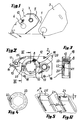
- a hand-held device for transferring a film from a carrier tape to a substrate which has a gear plate 1, an interchangeable cassette 2 and a swivel cover 3 which is pivotally attached to the gear plate 1 via a pivot pin 4.
- the interchangeable cassette 2 is inserted into a recess 5 in the transmission plate 1, a supply spool 8 (FIG. 2) provided in the interchangeable cassette 2 (FIG. 2) and a take-up reel 9 likewise arranged in the interchangeable cassette 2 can be rotatably attached to the rotating bolt 6 .
- a supply spool 8 (FIG. 2) provided in the interchangeable cassette 2 (FIG. 2)
- a take-up reel 9 likewise arranged in the interchangeable cassette 2 can be rotatably attached to the rotating bolt 6 .
- any design of pivot pins and coils suitable for a rotationally locking attachment can be used.
- a particularly suitable form is shown for example in Fig.
- the gear plate 1 covers a gear that connects the pivot pin 6 (as the drive pin) with the pivot pin 7 (as the output pin) with the interposition of a slip clutch.
- This gear ensures that when the supply reel 8 is unwound, a corresponding drive is transmitted to the take-up spool 9 via the rotation of the pivot pin 6 which is triggered, in such a way that the guidance of the carrier tape 11 between the supply spool 8 and take-up spool 9 is always kept taut .
- the occurring speed differences between the supply reel 8, the winding diameter of which continuously decreases, and the take-up reel 9, the winding diameter of which is always increasing, are compensated for by the slip clutch (not shown in the figures) within the transmission.
- a resilient support leg 13 is arranged in the interchangeable cassette 2, with its one end at which an application bar 14 is attached, protrudes from the cassette 2.
- the carrier tape 11 running from the winding supply 12 of the supply reel 8 is first led to this application bar 14, deflected at it, fed back into the cassette 2 and passed on to the take-up reel 9 via an intermediate spring tensioner 15.
- the side wall 16 of the exchangeable cassette 2 is fastened to the side wall (not shown in FIG. 2, removed) with the interposition of spacer bolts 18 in a suitable manner.
- FIGS. 5 and 6 two further, resilient tongues 20 are formed, which are shown in FIGS. 5 and 6 in an enlarged perspective view.
- the resilient tongues 20 are provided in the region of their free end with roof-shaped transverse ribs 21 which have a triangular cross section and converge at their angle projecting from the spring tongue 20 at an angle ⁇ which is not less than 30 ° and not greater than 60 °, preferably 45 °.
- Fig. 3 which shows a section along line III-III of Fig. 2, it can be seen that the supply spool 8 is provided at its end facing the side wall 16 of the exchangeable cassette 2 with a radially projecting flanged disc 23 against which the winding supply 12 lies on the coated carrier tape on this side.
- FIG. 4 shows a view of the take-up spool 8 from the side of the flanged disk 23, from which it can be seen that a circumferential row of projecting locking knobs 22, which is arranged concentrically to the central axis thereof, is formed on the flanged disk 23 and, as shown in FIG. 3, protrude from the flanged disk 23 in the direction of the side wall 16 of the exchangeable cassette 2.
- a circumferential row of projecting locking knobs 22 which is arranged concentrically to the central axis thereof
- the transverse channel 21 of the spring tongues 20 projects into one another between the two following locking knobs 22 formed space, so that the locking knobs 22 run continuously against the inclined side walls of the transverse trough 21 when the supply spool 8 is rotated and, when the rotary tongue 21 is rotated further, press the resilient tongue 21 outward until the respective locking knobs 22 can pass under the transverse trough 21. Subsequently, the spring tongue 20 immediately springs back in, whereby the transverse rib 21 engages in the space between the just passed through and the next locking knob 22. In this way, a plurality of rebound and spring-in movements of the spring tongues 20 are forced by the locking knobs 22 during one revolution of the carrier disk 23 and a corresponding braking torque is exerted on the carrier disk 23.
- the locking knobs 22 are designed as small truncated cones and are oriented such that they contact the total width of the transverse channel 21 in the central region when it passes by
- the transverse groove 21 is made in one piece with the resilient tongue 20 as part of the side wall 16 from a semi-impact resistant polystyrene, as is available on the market under the trade name "Vestyron 512".
- This plastic has a dielectric strength (according to DIN 53481)> 50kV / mm, a limit bending stress (according to DIN 53452, standard rod 2) of 600kp / cm2, a modulus of elasticity (according to DIN 53457 - from tensile tests according to DIN 53455) of 28,000kp / cm2 as well as a notched impact strength (Charpy impact test according to DIN 53453, standard rod according to Fig. 2, at + 20 ° C) of 4cmkp / cm2.
- Fig. 5 shows a resilient tongue 20 with a still undamaged cross rib 21, that is still in the state before the first use of the Cassette
- Fig. 6 shows the same spring tongue and cross rib after a long period of use (with only a small amount of winding 12 on the supply reel 8).
- a clear, wear-related recess 24 in the form of an irregular groove with a depth T can be seen on the transverse rib 21.
- This furrow 24 was introduced into the transverse rib 21 by the large number of locking knobs 22 passing by during the period of use of the cassette.
- the choice of the cross-sectional shape of the transverse rib 21 and the shape of the locking knobs 22 meshing with it, in particular by the choice of the angle of attack ⁇ between the two side surfaces delimiting the transverse rib 21 and the height of the initial coverage of the locking knobs 22 and the transverse rib 21, and also by the Selection of the material for the transverse rib 21 can be influenced in accordance with its intended wear behavior so that the braking torque exerted on the supply reel 8 shows the desired course depending on the unwinding path of the coated carrier tape 11, i. H. descends in the desired manner.
- each spring tongue 20 should be made as rigid as possible in the direction of the extension of the transverse ribs 21, so that at least no lateral deflections when Occur passing the locking knobs 22.
- the supply reel 8 as well as the flanged wheel 23 and the locking knobs 22 arranged thereon are preferably formed in one piece, wherein the same plastic as that used for the spring tongue 20 and transverse rib 21 can be used for them. Because the fact that each transverse rib 21 meshes with a large number of locking knobs 22 during one revolution of the flanged disk 23 has the effect that in any case wear occurring at the end edge 25 of the transverse rib 21 is relatively much greater than that on the intermeshing knobs 22 detectable wear, so that the latter is essentially irrelevant to the former.
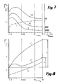
- curve 1 first shows the braking torque curve as it results when spring tongue is pressed axially against a flat end face of the coil core of a supply coil, the spring tongues coming into flat contact with this surface and the braking torque alone is expanded by the friction of the spring tongues pressed elastically against the coil core.
- the measurements were carried out (as with all other measurements shown in diagrams 7 and 8) only from the second turn of the supply reel 8, in order to take into account the winding of the leader tape, which is basically fast-forwarded by the operator during cassette assembly, while in the case of However, the consideration to be taken here is only interesting as to what the user feels afterwards, namely when using the hand-held device to transfer a film.
- the braking torque does not remain constant, but rather increases almost over the entire unwinding distance, undesirably, especially at the beginning where braking is required, the lowest values for the braking torque and later, where additional Braking resistors undesirable, if not harmful, set the maximum braking torque values.
- Curves II, III and IV which were created with an interchangeable cassette of the type according to the invention with targeted wear, on the other hand show the desired drop in braking torque with increasing tape consumption. These curves also initially show a certain increase in the braking torque (but only in a small initial range, which is between 10 and about 30 revolutions of the supply reel 8): this is an increase caused by the grinding in of the entire mechanism of the cassette occurs initially, but is of insignificant importance with regard to the desired overall behavior of the torque in this unwinding phase of the supply belt and compared to the important, occurring afterwards and which can be ascertained until the complete winding supply 12 has been completely processed, ongoing decrease in the braking torque M D is negligible.
- the curve I ' shows the course of the curve, which results for the pulling force under the measuring conditions of curve I from Fig. 7, so if the supply spool 8 is braked by pure friction by brake springs elastically pressed onto its end face (without wear effect). This shows that over the entire unwinding path, starting from a certain starting force required to start the cassette, an unacceptable increase in the practical use of the device P 'of the pulling force at the end of the unwinding path (namely after 130 revolutions of the Supply spool 8) occurs.
- the curve II ' was measured for the same handheld device and the same exchangeable cassette, which corresponds to the curve profile II from FIG. 7. This results in a much smaller increase P ⁇ of the pulling force at the end of the tape supply on the take-up reel 8, although the curve is based on the same initial value as the curve I '.
- any other suitable arrangement for building up a braking torque with the desired course over the unwinding path could also be used, for example a flanged disc 23 with spur teeth, into which Engage resilient tongues angled by 90 °, which are in turn formed on the side wall 16.
Landscapes
- Impression-Transfer Materials And Handling Thereof (AREA)
- Replacement Of Web Rolls (AREA)
- Registering, Tensioning, Guiding Webs, And Rollers Therefor (AREA)
- Adhesive Tape Dispensing Devices (AREA)
- Container, Conveyance, Adherence, Positioning, Of Wafer (AREA)
- Unwinding Webs (AREA)
Applications Claiming Priority (2)
| Application Number | Priority Date | Filing Date | Title |
|---|---|---|---|
| DE3907753 | 1989-03-10 | ||
| DE3907753A DE3907753C1 (OSRAM) | 1989-03-10 | 1989-03-10 |
Publications (2)
| Publication Number | Publication Date |
|---|---|
| EP0386500A1 EP0386500A1 (de) | 1990-09-12 |
| EP0386500B1 true EP0386500B1 (de) | 1993-09-15 |
Family
ID=6375993
Family Applications (1)
| Application Number | Title | Priority Date | Filing Date |
|---|---|---|---|
| EP90102941A Expired - Lifetime EP0386500B1 (de) | 1989-03-10 | 1990-02-15 | Auswechselkassette für ein Handgerät zum Übertragen eines Filmes von einem Trägerband auf ein Substrat |
Country Status (7)
| Country | Link |
|---|---|
| US (1) | US5125589A (OSRAM) |
| EP (1) | EP0386500B1 (OSRAM) |
| JP (1) | JP2540642B2 (OSRAM) |
| AT (1) | ATE94496T1 (OSRAM) |
| DE (2) | DE3907753C1 (OSRAM) |
| DK (1) | DK0386500T3 (OSRAM) |
| ES (1) | ES2044260T3 (OSRAM) |
Families Citing this family (27)
| Publication number | Priority date | Publication date | Assignee | Title |
|---|---|---|---|---|
| DE4220843C1 (OSRAM) * | 1992-06-25 | 1993-08-05 | Citius Buerotechnik Gmbh, 8906 Gersthofen, De | |
| US5310437A (en) * | 1992-10-15 | 1994-05-10 | The Gillette Company | Single spool correction tape dispenser |
| US5310445A (en) * | 1992-10-15 | 1994-05-10 | The Gillette Company | Tape dispenser |
| GB2275042B (en) | 1993-02-10 | 1995-10-25 | Gillette Co | Correction tape dispenser |
| US5499877A (en) * | 1993-04-06 | 1996-03-19 | Fujicopian Co., Ltd. | Transfer ribbon cassette, a case for enclosing the cassette, and a paint film transfer device having the same |
| DE4322118C1 (de) * | 1993-07-02 | 1994-11-17 | Pelikan Ag | Handgerät zum Übertragen eines Films von einem Trägerband auf ein Substrat |
| JP2807805B2 (ja) * | 1993-09-22 | 1998-10-08 | シードゴム工業株式会社 | 塗膜転写具 |
| JP2829699B2 (ja) * | 1993-12-03 | 1998-11-25 | シードゴム工業株式会社 | 塗膜転写具 |
| JP2943134B2 (ja) * | 1995-11-01 | 1999-08-30 | シードゴム工業株式会社 | 塗膜転写具用テープカートリッジおよび塗膜転写具 |
| JP3027309B2 (ja) * | 1994-12-12 | 2000-04-04 | シードゴム工業株式会社 | 塗膜転写具用テープカートリッジおよび塗膜転写具 |
| JP2869855B2 (ja) * | 1995-03-28 | 1999-03-10 | 株式会社トンボ鉛筆 | 字消し具 |
| US5549255A (en) * | 1995-04-10 | 1996-08-27 | Huang; Harrison | Silencer for tape dispenser |
| JPH0967808A (ja) * | 1995-08-31 | 1997-03-11 | Minnesota Mining & Mfg Co <3M> | 自走式舗装マーキングテープ貼付装置 |
| US6808565B1 (en) | 1995-10-06 | 2004-10-26 | Seed Rubber Co., Ltd. | Clutch mechanism of coat film transfer tool and coat film transfer tool |
| USD410494S (en) * | 1997-09-26 | 1999-06-01 | Bic Corporation | Correction-tape dispenser |
| USD410955S (en) * | 1998-12-11 | 1999-06-15 | Bic Corporation | Correction-tape dispenser |
| US20040033353A1 (en) * | 2002-03-14 | 2004-02-19 | You Kwang Ho | Adhesive tape |
| US6997229B2 (en) * | 2003-09-16 | 2006-02-14 | Sanford, L.P. | Rotatable applicator tip for a corrective tape dispenser |
| US20050056375A1 (en) * | 2003-09-16 | 2005-03-17 | Sanford, L.P. | Applicator tip for a corrective tape dispenser |
| WO2005030624A2 (en) * | 2003-09-26 | 2005-04-07 | Innodesk Business Tools, Inc. | Powered tape dispenser |
| US8397784B2 (en) | 2010-08-31 | 2013-03-19 | Sanford, L.P. | Correction tape dispenser with variable clutch mechanism |
| US8746313B2 (en) | 2010-12-29 | 2014-06-10 | Sanford, L.P. | Correction tape re-tensioning mechanism and correction tape dispenser comprising same |
| US8578999B2 (en) | 2010-12-29 | 2013-11-12 | Sanford, L.P. | Variable clutch mechanism and correction tape dispenser with variable clutch mechanism |
| US8746316B2 (en) | 2011-12-30 | 2014-06-10 | Sanford, L.P. | Variable clutch mechanism and correction tape dispenser with variable clutch mechanism |
| AU2014235587B2 (en) * | 2013-03-15 | 2016-12-08 | Elc Management Llc | False eyelash dispenser |
| FR3046786B1 (fr) * | 2016-01-15 | 2018-02-09 | Societe Bic | Dispositif manuel d'application par ruban d'un revetement sur un support presentant un embout d'application ameliore |
| TW202530033A (zh) * | 2024-01-25 | 2025-08-01 | 順德工業股份有限公司 | 塗膜轉印具 |
Family Cites Families (14)
| Publication number | Priority date | Publication date | Assignee | Title |
|---|---|---|---|---|
| GB487431A (OSRAM) * | ||||
| US1849383A (en) * | 1929-05-28 | 1932-03-15 | Richards Arthur Bruc Gillespie | Means for controlling the tension of coils or rolls of flexible material |
| US2277134A (en) * | 1940-06-28 | 1942-03-24 | Western Electric Co | Brake |
| US2859919A (en) * | 1954-06-09 | 1958-11-11 | Debrie Andre Victor Le Clement | Friction device for film spools |
| US2905404A (en) * | 1957-02-19 | 1959-09-22 | Walter J Simmons | Supply holder for rolled material |
| US3106324A (en) * | 1961-01-27 | 1963-10-08 | George H Fritzinger | Double-coated tape dispenser |
| GB965179A (en) * | 1961-11-26 | 1964-07-29 | Israel State | A speed limiting device for limiting the speed of rotation of a body |
| US3156324A (en) * | 1962-12-27 | 1964-11-10 | Earl F Colbert | Speed regulating attachment for tape recorders |
| US3434570A (en) * | 1967-05-15 | 1969-03-25 | Budd Co | Disk brake apparatus |
| US3902956A (en) * | 1973-12-06 | 1975-09-02 | Minnesota Mining & Mfg | Pressure-sensitive tape applicating system |
| JPS5515062U (OSRAM) * | 1978-07-17 | 1980-01-30 | ||
| JPS5656453A (en) * | 1979-10-16 | 1981-05-18 | Ricoh Co Ltd | Ribbon tension controller for ribbon cartridge |
| JPS57153844A (en) * | 1981-03-05 | 1982-09-22 | Sato Co Ltd | Device for printing and pasting label |
| DE3736357C2 (de) * | 1987-10-27 | 1995-11-09 | Pelikan Ag | Handgerät zum Übertragen eines Filmes von einer Trägerfolie auf ein Substrat |
-
1989
- 1989-03-10 DE DE3907753A patent/DE3907753C1/de not_active Expired - Lifetime
-
1990
- 1990-02-15 ES ES90102941T patent/ES2044260T3/es not_active Expired - Lifetime
- 1990-02-15 EP EP90102941A patent/EP0386500B1/de not_active Expired - Lifetime
- 1990-02-15 DE DE90102941T patent/DE59002685D1/de not_active Expired - Lifetime
- 1990-02-15 AT AT90102941T patent/ATE94496T1/de not_active IP Right Cessation
- 1990-02-15 DK DK90102941.3T patent/DK0386500T3/da active
- 1990-03-12 US US07/491,738 patent/US5125589A/en not_active Expired - Lifetime
- 1990-03-12 JP JP2058254A patent/JP2540642B2/ja not_active Expired - Fee Related
Also Published As
| Publication number | Publication date |
|---|---|
| JPH0387283A (ja) | 1991-04-12 |
| US5125589A (en) | 1992-06-30 |
| ATE94496T1 (de) | 1993-10-15 |
| DE3907753C1 (OSRAM) | 1990-09-06 |
| JP2540642B2 (ja) | 1996-10-09 |
| EP0386500A1 (de) | 1990-09-12 |
| DK0386500T3 (da) | 1994-02-07 |
| DE59002685D1 (de) | 1993-10-21 |
| ES2044260T3 (es) | 1994-01-01 |
Similar Documents
| Publication | Publication Date | Title |
|---|---|---|
| EP0386500B1 (de) | Auswechselkassette für ein Handgerät zum Übertragen eines Filmes von einem Trägerband auf ein Substrat | |
| DE3007948C2 (de) | Kassette für einen bandförmigen Aufzeichnungsträger | |
| EP1222131B1 (de) | Handgerät zum übertragen eines filmes von einem trägerband auf ein substrat, mit einer rücklaufsperre | |
| EP0886621B1 (de) | Getriebeanordnung zum antrieb des spulenkerns einer aufwickelspule für ein transferband eines transferdispensers | |
| EP1200332A1 (de) | Handgerät zum übertragen eines filmes von einem trägerband auf ein substrat | |
| DE3514289C2 (OSRAM) | ||
| EP0368070A2 (de) | Handgerät zum Ubertragen eines Filmes von einem Trägerband auf ein Substrat | |
| EP0993414A1 (de) | Spulenanordnung | |
| DE19702345A1 (de) | Handgerät zum Übertragen eines Filmes von einem Trägerband auf ein Substrat | |
| DE3538048C2 (OSRAM) | ||
| DE2634817C3 (de) | Vorrichtung zum Erzeugen eines selbsttätig hin- und hergehenden Vorschubs | |
| DE69633099T2 (de) | Kupplungsmechanismus eines Übertragungswerkzeuges für Beschichtungsfilme und Übertragungswerkzeug für Beschichtungsfilme | |
| DE3911402A1 (de) | Vorrichtung zum aufbringen eines adhaesiven materials | |
| EP1071629B1 (de) | Handgerät zum übertragen eines filmes von einem trägerband auf ein substrat | |
| DE3632066A1 (de) | Vorrichtung zum beseitigen der spannung fuer eine rueckzugsvorrichtung eines sicherheitsgurts eines fahrzeugs | |
| EP0167142B1 (de) | Brems- und Bandspannvorrichtung für Bandkassetten mit Flanschspulen und Bandkassette, insbesondere Magnetbandkassette, damit | |
| EP0479001B1 (de) | Wechselkassette | |
| DE2717161C2 (de) | Bremsmechanismus für einen optischen Schlitzverschluß | |
| EP0077972B1 (de) | Haken-Klemmspule | |
| DE1929945C3 (de) | Fadenführerantneb an Kreuzspulma schinen | |
| DE4020858C2 (OSRAM) | ||
| DE4141610C2 (de) | Rücklaufsperre für ein Handetikettiergerät | |
| DE948758C (de) | Rollfilmkamera | |
| AT405927B (de) | Spulenanordnung für eine vorrichtung zum übertragen eines auf einem folienband einseitig vorliegenden films auf einen träger | |
| DE1774377C (de) | Kassette fur eine in dieser drehbar angeordnete Flanschspule |
Legal Events
| Date | Code | Title | Description |
|---|---|---|---|
| PUAI | Public reference made under article 153(3) epc to a published international application that has entered the european phase |
Free format text: ORIGINAL CODE: 0009012 |
|
| 17P | Request for examination filed |
Effective date: 19900215 |
|
| AK | Designated contracting states |
Kind code of ref document: A1 Designated state(s): AT BE CH DE DK ES FR GB GR IT LI LU NL SE |
|
| 17Q | First examination report despatched |
Effective date: 19920325 |
|
| GRAA | (expected) grant |
Free format text: ORIGINAL CODE: 0009210 |
|
| AK | Designated contracting states |
Kind code of ref document: B1 Designated state(s): AT BE CH DE DK ES FR GB GR IT LI LU NL SE |
|
| REF | Corresponds to: |
Ref document number: 94496 Country of ref document: AT Date of ref document: 19931015 Kind code of ref document: T |
|
| REF | Corresponds to: |
Ref document number: 59002685 Country of ref document: DE Date of ref document: 19931021 |
|
| GBT | Gb: translation of ep patent filed (gb section 77(6)(a)/1977) |
Effective date: 19931020 |
|
| ET | Fr: translation filed | ||
| ITF | It: translation for a ep patent filed | ||
| REG | Reference to a national code |
Ref country code: GR Ref legal event code: FG4A Free format text: 3009311 |
|
| REG | Reference to a national code |
Ref country code: DK Ref legal event code: T3 |
|
| REG | Reference to a national code |
Ref country code: CH Ref legal event code: PFA Free format text: PELIKAN GMBH |
|
| RAP2 | Party data changed (patent owner data changed or rights of a patent transferred) |
Owner name: PELIKAN GMBH |
|
| EPTA | Lu: last paid annual fee | ||
| NLT2 | Nl: modifications (of names), taken from the european patent patent bulletin |
Owner name: PELIKAN GMBH TE HANNOVER, BONDSREPUBLIEK DUITSLAND |
|
| ITPR | It: changes in ownership of a european patent |
Owner name: TRASFORMAZIONE SOCIETARIA;PELIKAN GMBH |
|
| PLBE | No opposition filed within time limit |
Free format text: ORIGINAL CODE: 0009261 |
|
| STAA | Information on the status of an ep patent application or granted ep patent |
Free format text: STATUS: NO OPPOSITION FILED WITHIN TIME LIMIT |
|
| NLS | Nl: assignments of ep-patents |
Owner name: PELIKAN GMBH TE HANNOVER, BONDSREPUBLIEK DUITSLAND |
|
| 26N | No opposition filed | ||
| REG | Reference to a national code |
Ref country code: FR Ref legal event code: CJ |
|
| EAL | Se: european patent in force in sweden |
Ref document number: 90102941.3 |
|
| REG | Reference to a national code |
Ref country code: CH Ref legal event code: PUE Owner name: PELIKAN GMBH TRANSFER- PRITT PRODUKTIONSGESELLSCHA |
|
| NLS | Nl: assignments of ep-patents |
Owner name: PRITT PRODUKTIONSGESELLSCHAFT MBH |
|
| REG | Reference to a national code |
Ref country code: GB Ref legal event code: 732E |
|
| REG | Reference to a national code |
Ref country code: FR Ref legal event code: TP |
|
| REG | Reference to a national code |
Ref country code: ES Ref legal event code: PC2A Owner name: PRITT PRODUKTIONSGESELLSCHAFT MBH |
|
| PGFP | Annual fee paid to national office [announced via postgrant information from national office to epo] |
Ref country code: SE Payment date: 20010206 Year of fee payment: 12 |
|
| PGFP | Annual fee paid to national office [announced via postgrant information from national office to epo] |
Ref country code: CH Payment date: 20010213 Year of fee payment: 12 Ref country code: DK Payment date: 20010213 Year of fee payment: 12 Ref country code: LU Payment date: 20010213 Year of fee payment: 12 |
|
| REG | Reference to a national code |
Ref country code: GB Ref legal event code: IF02 |
|
| PG25 | Lapsed in a contracting state [announced via postgrant information from national office to epo] |
Ref country code: LU Free format text: LAPSE BECAUSE OF NON-PAYMENT OF DUE FEES Effective date: 20020215 |
|
| PG25 | Lapsed in a contracting state [announced via postgrant information from national office to epo] |
Ref country code: SE Free format text: LAPSE BECAUSE OF NON-PAYMENT OF DUE FEES Effective date: 20020216 |
|
| PG25 | Lapsed in a contracting state [announced via postgrant information from national office to epo] |
Ref country code: CH Free format text: LAPSE BECAUSE OF NON-PAYMENT OF DUE FEES Effective date: 20020228 Ref country code: LI Free format text: LAPSE BECAUSE OF NON-PAYMENT OF DUE FEES Effective date: 20020228 Ref country code: DK Free format text: LAPSE BECAUSE OF NON-PAYMENT OF DUE FEES Effective date: 20020228 |
|
| EUG | Se: european patent has lapsed |
Ref document number: 90102941.3 |
|
| REG | Reference to a national code |
Ref country code: DK Ref legal event code: EBP |
|
| REG | Reference to a national code |
Ref country code: CH Ref legal event code: PL |
|
| PGFP | Annual fee paid to national office [announced via postgrant information from national office to epo] |
Ref country code: AT Payment date: 20060213 Year of fee payment: 17 |
|
| PGFP | Annual fee paid to national office [announced via postgrant information from national office to epo] |
Ref country code: GB Payment date: 20060215 Year of fee payment: 17 |
|
| PGFP | Annual fee paid to national office [announced via postgrant information from national office to epo] |
Ref country code: IT Payment date: 20060228 Year of fee payment: 17 |
|
| PGFP | Annual fee paid to national office [announced via postgrant information from national office to epo] |
Ref country code: ES Payment date: 20060317 Year of fee payment: 17 |
|
| GBPC | Gb: european patent ceased through non-payment of renewal fee |
Effective date: 20070215 |
|
| PG25 | Lapsed in a contracting state [announced via postgrant information from national office to epo] |
Ref country code: AT Free format text: LAPSE BECAUSE OF NON-PAYMENT OF DUE FEES Effective date: 20070215 |
|
| PGFP | Annual fee paid to national office [announced via postgrant information from national office to epo] |
Ref country code: GR Payment date: 20070111 Year of fee payment: 18 |
|
| PG25 | Lapsed in a contracting state [announced via postgrant information from national office to epo] |
Ref country code: GB Free format text: LAPSE BECAUSE OF NON-PAYMENT OF DUE FEES Effective date: 20070215 |
|
| REG | Reference to a national code |
Ref country code: ES Ref legal event code: FD2A Effective date: 20070216 |
|
| PG25 | Lapsed in a contracting state [announced via postgrant information from national office to epo] |
Ref country code: ES Free format text: LAPSE BECAUSE OF NON-PAYMENT OF DUE FEES Effective date: 20070216 |
|
| PGFP | Annual fee paid to national office [announced via postgrant information from national office to epo] |
Ref country code: NL Payment date: 20090203 Year of fee payment: 20 Ref country code: DE Payment date: 20090213 Year of fee payment: 20 |
|
| PG25 | Lapsed in a contracting state [announced via postgrant information from national office to epo] |
Ref country code: GR Free format text: LAPSE BECAUSE OF NON-PAYMENT OF DUE FEES Effective date: 20080903 |
|
| PGFP | Annual fee paid to national office [announced via postgrant information from national office to epo] |
Ref country code: BE Payment date: 20090225 Year of fee payment: 20 |
|
| PG25 | Lapsed in a contracting state [announced via postgrant information from national office to epo] |
Ref country code: IT Free format text: LAPSE BECAUSE OF NON-PAYMENT OF DUE FEES Effective date: 20070215 |
|
| PGFP | Annual fee paid to national office [announced via postgrant information from national office to epo] |
Ref country code: FR Payment date: 20090213 Year of fee payment: 20 |
|
| BE20 | Be: patent expired |
Owner name: *PRITT PRODUKTIONS G.M.B.H. Effective date: 20100215 |
|
| NLV7 | Nl: ceased due to reaching the maximum lifetime of a patent |
Effective date: 20100215 |
|
| PG25 | Lapsed in a contracting state [announced via postgrant information from national office to epo] |
Ref country code: DE Free format text: LAPSE BECAUSE OF EXPIRATION OF PROTECTION Effective date: 20100215 |