EP0383362B1 - Vorrichtung zum Verfüllen von bergmännisch hergestellten Hohlräumen, insbesondere im Steinkohlenbergbau - Google Patents
Vorrichtung zum Verfüllen von bergmännisch hergestellten Hohlräumen, insbesondere im Steinkohlenbergbau Download PDFInfo
- Publication number
- EP0383362B1 EP0383362B1 EP90105784A EP90105784A EP0383362B1 EP 0383362 B1 EP0383362 B1 EP 0383362B1 EP 90105784 A EP90105784 A EP 90105784A EP 90105784 A EP90105784 A EP 90105784A EP 0383362 B1 EP0383362 B1 EP 0383362B1
- Authority
- EP
- European Patent Office
- Prior art keywords
- packing
- section
- support frame
- free ends
- packing wall
- Prior art date
- Legal status (The legal status is an assumption and is not a legal conclusion. Google has not performed a legal analysis and makes no representation as to the accuracy of the status listed.)
- Expired - Lifetime
Links
- 239000003245 coal Substances 0.000 title claims description 4
- 238000000034 method Methods 0.000 title description 5
- 238000009412 basement excavation Methods 0.000 title 1
- 239000000463 material Substances 0.000 claims description 36
- 238000005065 mining Methods 0.000 claims description 5
- 238000012856 packing Methods 0.000 claims 21
- 238000000465 moulding Methods 0.000 claims 5
- 239000012858 resilient material Substances 0.000 claims 2
- 238000005056 compaction Methods 0.000 claims 1
- 239000013013 elastic material Substances 0.000 description 7
- 230000000875 corresponding effect Effects 0.000 description 4
- 238000006073 displacement reaction Methods 0.000 description 4
- 239000000945 filler Substances 0.000 description 3
- 238000010276 construction Methods 0.000 description 2
- 238000011161 development Methods 0.000 description 2
- 230000018109 developmental process Effects 0.000 description 2
- 238000005516 engineering process Methods 0.000 description 2
- 239000002699 waste material Substances 0.000 description 2
- 230000015572 biosynthetic process Effects 0.000 description 1
- 238000007664 blowing Methods 0.000 description 1
- 239000004568 cement Substances 0.000 description 1
- 230000000694 effects Effects 0.000 description 1
- 238000003780 insertion Methods 0.000 description 1
- 230000037431 insertion Effects 0.000 description 1
- 239000002184 metal Substances 0.000 description 1
- 239000004033 plastic Substances 0.000 description 1
- 229920003023 plastic Polymers 0.000 description 1
- 238000007665 sagging Methods 0.000 description 1
- 238000007789 sealing Methods 0.000 description 1
- 238000007711 solidification Methods 0.000 description 1
- 230000008023 solidification Effects 0.000 description 1
- 230000006641 stabilisation Effects 0.000 description 1
- 238000011105 stabilization Methods 0.000 description 1
- 230000007704 transition Effects 0.000 description 1
Images


Classifications
-
- E—FIXED CONSTRUCTIONS
- E21—EARTH OR ROCK DRILLING; MINING
- E21F—SAFETY DEVICES, TRANSPORT, FILLING-UP, RESCUE, VENTILATION, OR DRAINING IN OR OF MINES OR TUNNELS
- E21F15/00—Methods or devices for placing filling-up materials in underground workings
-
- B—PERFORMING OPERATIONS; TRANSPORTING
- B09—DISPOSAL OF SOLID WASTE; RECLAMATION OF CONTAMINATED SOIL
- B09B—DISPOSAL OF SOLID WASTE NOT OTHERWISE PROVIDED FOR
- B09B1/00—Dumping solid waste
- B09B1/008—Subterranean disposal, e.g. in boreholes or subsurface fractures
-
- E—FIXED CONSTRUCTIONS
- E21—EARTH OR ROCK DRILLING; MINING
- E21D—SHAFTS; TUNNELS; GALLERIES; LARGE UNDERGROUND CHAMBERS
- E21D23/00—Mine roof supports for step- by- step movement, e.g. in combination with provisions for shifting of conveyors, mining machines, or guides therefor
- E21D23/04—Structural features of the supporting construction, e.g. linking members between adjacent frames or sets of props; Means for counteracting lateral sliding on inclined floor
- E21D23/0481—Supports specially adapted for use in combination with the placing of filling-up materials
Definitions
- the invention relates to a device for filling mined cavities, especially in coal mining, according to the preamble of claim 1.
- the working direction for a corresponding device is the direction of the progress of the dismantling.
- the next offset wall section is drawn up and backfill material is blown into the further developed offset space.
- a new strip of filling material which extends across the width of the filling area, is gradually created in the transverse direction.
- the individual offset wall sections are essentially flat plates. Consequently, the offset spaces behind the offset wall sections are not laterally limited. From this it follows again that when the backfill material is introduced from the delivery line, the respective offset space is open to one side. The backfill material would therefore emerge unhindered from the offset space if filler material were not only introduced in the most distant edge region of the offset space. In terms of process technology, it is practically impossible to insert the backfill material until it touches the slope.
- a device for filling mined cavities is known (DE-B 2 549 486), with which it is possible to create clearly delimited sections in the transverse direction without the continuous strip-like filling of the mined cavity being abandoned as a result .
- a one-piece offset wall i. H. namely an offset wall section, which is L-shaped in plan view, crazy in the transverse direction. If an offset section produced in this way is solidified, the offset wall is laterally displaced laterally by a section, so that backfill material can be introduced into the new offset space formed, which is laterally delimited by the L-leg of the offset wall.
- This device works slowly since it can only be advanced further in the transverse direction when the previous offset section has solidified.
- the invention has for its object to design and develop the above-described known device so that with it the filling material can be introduced and compacted quickly and effectively in individual, separate offset sections particularly close to the dismantling front.
- the formation of the offset wall according to the invention makes it possible to early, after advancement, for. B. a support frame also the associated offset wall section to advance and to fill the offset space section enclosed by this offset wall section by introducing hydraulically setting filler material as far as possible under the slope. This is due to the fact that the offset space sections are closely enclosed on all sides, namely on the one hand by the section of the strip previously created, on the other hand by the corresponding offset wall section.
- the extension frame forms pillar-shaped sections that immediately provide a high resistance to the sagging roof layers.
- tapering, pillar-like sections Another advantage of the tapering, pillar-like sections is that they do not hinder the back offset wall. Lateral movements of the expansion racks are also possible after appropriate distance from the solidified section.
- the pillar-like sections are gradually refilled in a particularly clever manner, so that the result is a completely and compactly filled cavity.
- the device designed according to the invention can also be used when working in such a narrow, mined cavity that only a single offset wall section is provided.
- the free ends of the offset wall section then slidingly and sealingly against the sides of the cavity likewise result in the gapless, complete and compact filling of the mined cavity.
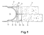
- Fig. 1 shows a preferred embodiment of a device according to the invention for filling mined cavities, especially in coal mining, with a backfill material with a dense structure in the final state and high, preferably rapidly occurring solidification.
- 1 shows an offset wall section 2 of the device, of which this device has a plurality arranged side by side.
- An expansion frame 3 is assigned to the offset wall section 2.
- the expansion rack 3 consists in the embodiment shown here from two trestles 4, which are connected to a trestle in a known manner with each other or with a conveyor by means of back cylinders, so that the expansion rack 3 can advance according to the progress of dismantling.
- each support frame 4 of the support frame 3 consists of a base plate 5, three hydraulic rams 6 and a cap 7. This is very clearly shown in FIG. 1 in conjunction with FIG. 2. Indicated in FIG. 1 and drawn in FIG. 2 are further clamping punches 8, which are assigned to the offset wall section 2, here a total of four clamping punches 8. Furthermore, a conveying device for filling material designed as a conveying line 9 can be seen.
- the mechanical implementation of the measures for stabilization between the base plate and the cap can be carried out in a known manner as in the case of trestle combinations and / or in the case of shields with four-bar gears.
- Fig. 3 makes it clear that the offset wall sections 2 together form a continuous, the open cavity, in particular the longwall 10, against a displacement wall 11 to be filled with filler material delimiting offset wall.
- the longwall 10 and the offset space 11, the latter already filled with filling material are shown.
- the removal frames 3 of the device are self-advancing and the offset wall sections 2 are retractable and height-adjustable and can be braced by means of the tensioning stamp 8 to the hanging 12 and lying 13 (FIG. 2).
- Such a device is particularly suitable for carrying out a method according to the parent patent 0 293 686.
- each offset wall section 2 is U-shaped in cross section and surrounds open on the offset side, tapering offset space section 14 tapering in the backward direction - working direction - and that the free ends of adjacent offset wall sections 2 are at least over the Stride length of the expansion frame 3 slide and seal against each other and that the outer width and the maximum inside width of the offset wall sections 2 is larger at the free ends sliding against each other than in the rest.
- each offset wall section 2 has a support frame 15 and a one-piece or multi-part molded plate 17 made of elastic material and attached to the support frame 15, which corresponds to the contour of the offset wall section 2, and which are in sliding contact with one another free ends of the offset wall sections 2 are formed by the ends of the mold plates 17.
- the elastic material is expediently a rubber-like material, although certain plastics already have corresponding properties nowadays. It is essential that this results in a flexible construction that is sufficiently strong on the one hand to absorb the forces exerted by the as yet unconsolidated filling material, but on the other hand is sufficiently mobile to easily detach from the pillar-like filling material after the filling material has solidified.
- the form plates made of elastic material which slide directly against one another in the area of the free ends easily create a sufficiently tight demarcation from the neighboring pillar-like filling material.
- these ends permit the seamless backfilling in the border area to the adjacent pillar, which is explained in the general part of the description, in a particularly expedient manner without additional measures.
- this is a one-piece molded plate 17 made of elastic material.
- a multi-part molded plate could just as well be used if this would be preferable for design reasons.
- the support frame is approximately U-shaped in cross-section and that the molded plate made of elastic material consists of two parts which only form the free ends and are fastened to the support frame.
- the "shape" for the pillar-like section largely consist of wear-resistant metal of the support frame, so that only the ends required for the sliding seal are made of elastic and thus more wear-resistant material.
- the above-described width ratios are realized in that the outer width of the support frame 15 is smaller than the outer width of the shaped plate 17 at the free ends and the maximum inner width of the offset wall section 2 in the area of Support frame 15 is less than at the free ends of the mold plate 17th
- the support frame 15 can expediently be fastened to the clamping plungers 8.
- the support frame 15 is expediently height-adjustable with the aid of the clamping ram 8 and between the hanging line 12 and the lying 13 can be braced.
- the construction should be such that the molded plate 17 attached to the support frame 15 is deformed at the same time and thus rests sealingly on the hanging ends 12 and lying ends 13.
- the support frame 15 is connected to the base plates 5 and the caps 7 of the extension frame 3 by means of suitable rear devices 16 and can be retightened after the back of the removal frame 3 with the aid of these rear devices 16 at a suitable time.
- the rear devices 16 can also serve to advance the expansion frame 3, the solidified section 1 serving as an abutment.
- each offset wall section 2 has at least one opening 18 for receiving the delivery line 9 or one of the delivery line for backfill mechanics, only a common delivery line 9 running transversely to the back direction - working direction - being provided here.
- FIG. 3 shows the method of operation of the device according to the invention using a device with a total of four offset sections 2.
- the offset wall section 2 shown above in FIG. 3 is in the basic position after the pillar-like section 1 has been formed.
- the offset wall section 2 located below in FIG. 3 shows an expansion stand 4 of the associated removal frame advanced according to the progress of the dismantling; Extension frame 3 advanced.
- an offset wall section 2 is shown, which has already been retracted following the advanced expansion frame 3, so that between the remaining, already solidified, pillar-like section 1 and the advanced offset wall section 2, a new offset space section 14 has been created, to be filled with filling material .
- the device according to the invention is particularly suitable for introducing different filling material with or without (industrial) residues and waste materials into a cavity according to the method explained in the parent patent 0 293 686.
- the checkerboard-like insertion proposed there can be implemented particularly expediently by the device according to the invention.
- the device according to the invention can, for. B. have a total length of approximately 4,500 mm instead of the previously usual approximately 6,000 mm.
- the depth of the mold plate can be approx. 2,400 mm with a final overhang of 800 mm and a corresponding step size.
Landscapes
- Engineering & Computer Science (AREA)
- Mining & Mineral Resources (AREA)
- Life Sciences & Earth Sciences (AREA)
- General Life Sciences & Earth Sciences (AREA)
- Geochemistry & Mineralogy (AREA)
- Geology (AREA)
- Environmental & Geological Engineering (AREA)
- Architecture (AREA)
- Structural Engineering (AREA)
- Processing Of Solid Wastes (AREA)
- Consolidation Of Soil By Introduction Of Solidifying Substances Into Soil (AREA)
- Bulkheads Adapted To Foundation Construction (AREA)
Applications Claiming Priority (4)
| Application Number | Priority Date | Filing Date | Title |
|---|---|---|---|
| DE3718512 | 1987-06-03 | ||
| DE3718512 | 1987-06-03 | ||
| DE3720080 | 1987-06-16 | ||
| DE19873720080 DE3720080A1 (de) | 1987-06-03 | 1987-06-16 | Verfahren und vorrichtung zum verfuellen von hohlraeumen in bergmaennischen gewinnungsbetrieben, insbesondere im steinkohlenbergbau |
Related Parent Applications (1)
| Application Number | Title | Priority Date | Filing Date |
|---|---|---|---|
| EP88108094.9 Division | 1988-05-20 |
Publications (3)
| Publication Number | Publication Date |
|---|---|
| EP0383362A2 EP0383362A2 (de) | 1990-08-22 |
| EP0383362A3 EP0383362A3 (en) | 1990-09-05 |
| EP0383362B1 true EP0383362B1 (de) | 1993-09-15 |
Family
ID=25856239
Family Applications (2)
| Application Number | Title | Priority Date | Filing Date |
|---|---|---|---|
| EP90105784A Expired - Lifetime EP0383362B1 (de) | 1987-06-03 | 1988-05-20 | Vorrichtung zum Verfüllen von bergmännisch hergestellten Hohlräumen, insbesondere im Steinkohlenbergbau |
| EP88108094A Expired - Lifetime EP0293686B1 (de) | 1987-06-03 | 1988-05-20 | Verfahren zum Verfüllen von bergmännisch hergestellten Hohlräumen und Vorrichtung zur Durchführung eines entsprechenden Verfahrens |
Family Applications After (1)
| Application Number | Title | Priority Date | Filing Date |
|---|---|---|---|
| EP88108094A Expired - Lifetime EP0293686B1 (de) | 1987-06-03 | 1988-05-20 | Verfahren zum Verfüllen von bergmännisch hergestellten Hohlräumen und Vorrichtung zur Durchführung eines entsprechenden Verfahrens |
Country Status (2)
| Country | Link |
|---|---|
| EP (2) | EP0383362B1 (enExample) |
| DE (3) | DE3720080A1 (enExample) |
Cited By (3)
| Publication number | Priority date | Publication date | Assignee | Title |
|---|---|---|---|---|
| CN102261257A (zh) * | 2011-08-04 | 2011-11-30 | 成云海 | 用于架后充填的液压支架及其操作使用方法 |
| CN106988782A (zh) * | 2017-05-23 | 2017-07-28 | 中国神华能源股份有限公司 | 煤矿井下防火密闭墙构筑方法 |
| CN109973145A (zh) * | 2019-04-11 | 2019-07-05 | 兖矿东华重工有限公司 | 一种充填支架 |
Families Citing this family (6)
| Publication number | Priority date | Publication date | Assignee | Title |
|---|---|---|---|---|
| FR2909032B1 (fr) | 2006-11-27 | 2011-04-29 | Georgia Pacific France | Chambre a racles a au moins deux compartiments contenant des fluides differents. |
| CN102979545A (zh) * | 2012-12-10 | 2013-03-20 | 中国矿业大学 | 大采高前后部顶梁同轴铰接充填采煤液压支架 |
| CN104727847B (zh) * | 2015-01-14 | 2016-11-02 | 中国矿业大学 | 充填墙体自消除的无煤柱沿空留巷方法 |
| CN111237011B (zh) * | 2020-04-29 | 2020-07-28 | 矿冶科技集团有限公司 | 一种地下矿山充填采场快速封闭骨架及装置 |
| CN116147693A (zh) * | 2022-12-13 | 2023-05-23 | 中国矿业大学 | 一种煤矿密闭内环境信息感知物联网传感器及其使用方法 |
| CN118548012B (zh) * | 2024-06-06 | 2025-02-11 | 中国矿业大学(北京) | 矿区采后分段定向注浆修复含水层的方法 |
Family Cites Families (11)
| Publication number | Priority date | Publication date | Assignee | Title |
|---|---|---|---|---|
| DE1114155B (de) * | 1957-04-05 | 1961-09-28 | Dr Karl Lehmann | Verfahren und Anordnung zum Abkleiden von Bergeversatz beim Abbau floezartiger Lagerstaetten |
| DE1987711U (de) * | 1967-03-04 | 1968-06-20 | Bergwerksverband Gmbh | Blasversatzleitung fuer den bergbau mit ein- und ausschaltbaren austragsvorrichtungen. |
| DE1951117A1 (de) * | 1969-10-10 | 1971-04-22 | Bergwerksverband Gmbh | Einrichtung zum Einbringen von Blasversatz in Streben mit schreitendem Ausbau |
| GB1363887A (en) * | 1971-09-21 | 1974-08-21 | Thyssen Great Britain Ltd | Mining |
| GB1484568A (en) * | 1974-08-12 | 1977-09-01 | Cementation Mining Ltd | Shuttering device |
| GB1500180A (en) * | 1975-07-11 | 1978-02-08 | Coal Ind | Mine packing equipment |
| DE2549985C2 (de) * | 1975-11-07 | 1977-10-27 | Klöckner-Werke AG, 4100 Duisburg | Schildausbau und Verfahren zu seiner Verwendung |
| GB1514751A (en) * | 1976-05-25 | 1978-06-21 | Coal Ind | Mine roof support equipment |
| DE2943748A1 (de) * | 1979-10-30 | 1981-05-14 | Thyssen Industrie Ag, 4300 Essen | Hoehenverstellbare blasversatzwand |
| DE3413602C2 (de) * | 1984-04-11 | 1986-04-24 | Bergwerksverband Gmbh, 4300 Essen | Verfahren zum Versetzen der Hohlräume eines Bruchfeldes |
| DE3440783C2 (de) * | 1984-11-08 | 1986-11-20 | Bergwerksverband Gmbh, 4300 Essen | Rohrleitung für das Nachversetzen von untertägigen Hohlräumen |
-
1987
- 1987-06-16 DE DE19873720080 patent/DE3720080A1/de active Granted
-
1988
- 1988-05-20 EP EP90105784A patent/EP0383362B1/de not_active Expired - Lifetime
- 1988-05-20 DE DE8888108094T patent/DE3861630D1/de not_active Expired - Fee Related
- 1988-05-20 DE DE90105784T patent/DE3884211D1/de not_active Expired - Fee Related
- 1988-05-20 EP EP88108094A patent/EP0293686B1/de not_active Expired - Lifetime
Cited By (4)
| Publication number | Priority date | Publication date | Assignee | Title |
|---|---|---|---|---|
| CN102261257A (zh) * | 2011-08-04 | 2011-11-30 | 成云海 | 用于架后充填的液压支架及其操作使用方法 |
| CN102261257B (zh) * | 2011-08-04 | 2013-06-26 | 安徽理工大学 | 用于架后充填的液压支架及其操作使用方法 |
| CN106988782A (zh) * | 2017-05-23 | 2017-07-28 | 中国神华能源股份有限公司 | 煤矿井下防火密闭墙构筑方法 |
| CN109973145A (zh) * | 2019-04-11 | 2019-07-05 | 兖矿东华重工有限公司 | 一种充填支架 |
Also Published As
| Publication number | Publication date |
|---|---|
| DE3720080C2 (enExample) | 1990-03-22 |
| DE3720080A1 (de) | 1989-01-05 |
| EP0383362A2 (de) | 1990-08-22 |
| EP0293686B1 (de) | 1991-01-23 |
| EP0383362A3 (en) | 1990-09-05 |
| EP0293686A1 (de) | 1988-12-07 |
| DE3884211D1 (de) | 1993-10-21 |
| DE3861630D1 (de) | 1991-02-28 |
Similar Documents
| Publication | Publication Date | Title |
|---|---|---|
| DE2310077A1 (de) | Schreitende ausbauanlage fuer den bergbau | |
| DE2550050C2 (de) | Einrichtung zum Auffahren von Tunnels o.dgl. mittels eines Verbauschildes unter Einbringen einer Ortbetonauskleidung | |
| DE3720080C2 (enExample) | ||
| DE2720179B2 (de) | Ausbaugespann, bestehend aus schild- oder bockartigen Ausbaugestellen | |
| DE4029632A1 (de) | Abstuetzvorrichtung fuer eine offene, wandernde baugrube | |
| DE2246125A1 (de) | Schalungsvorrichtung zur packung von grubenabraummaterial | |
| DE2646563C3 (de) | Ausbau für den Saumbereich eines Strebs | |
| DE2325480C2 (de) | Ausbaugestell für den Strebausbau im untertägigen Grubenbetrieb | |
| DE2211605C3 (de) | Wandernder Streckenausbau | |
| DE7031383U (de) | Strebausbauelement fuer den strebausbau im bereich eines dem streo nachzufuehrenden bergedammes. | |
| EP0205853A2 (de) | Verfahren zum Herstellen eines röhrenförmigen unterirdischen Hohlraums, z.B. eines Tunnels, Stollens oder dergleichen im Schildvortrieb sowie Vorrichtung zum Durchführen des Verfahrens | |
| EP0250606A1 (de) | Verfahren und Vorrichtung zum nachträglichen Einbau von Bauelementen auf einer ausgedehnten Sohle im Erdboden im Untertagebau | |
| DE2706244A1 (de) | Verfahren und einrichtung zum vortrieb von tunneln, stollen u.dgl. unter gleichzeitigem einbringen einer betonauskleidung | |
| DE2401832C2 (de) | An schreitendem Ausbau nachgeführte Versatzwand, insbesondere für mächtige Flöze und Spülversatz | |
| DE1583039B1 (de) | Strebausruestung mit Gewinnungsmaschine fuer einen Kurzstreb | |
| AT390819B (de) | Ausbau fuer einen kalottenschlitz | |
| DE19712413C1 (de) | Hydraulisches Schreitausbaugestell | |
| DE2047769C3 (de) | Grubenausbau für das Strebende | |
| DE2164365C3 (de) | Rückbare Schildausbaueinheit | |
| DE3409002C2 (enExample) | ||
| DE3411638C2 (enExample) | ||
| DE2646586A1 (de) | Vortriebsschild, insbesondere fuer den vortrieb von gesteins- und floezstrecken in bergbau-untertagebetrieben | |
| DE1458679C3 (de) | Wandernder Ausbau für den untertägigen Grubenbetrieb | |
| DE3528864A1 (de) | Vorrichtung zum einbringen einer fluessigkeitsundurchlaessigen schicht in eine deponiehalde | |
| DE2104480C2 (de) | Wandernder hydraulischer Ausbau zur Abstützung der dem alten Mann zugewandten Seite einer Abbaustrecke |
Legal Events
| Date | Code | Title | Description |
|---|---|---|---|
| PUAI | Public reference made under article 153(3) epc to a published international application that has entered the european phase |
Free format text: ORIGINAL CODE: 0009012 |
|
| PUAL | Search report despatched |
Free format text: ORIGINAL CODE: 0009013 |
|
| AC | Divisional application: reference to earlier application |
Ref document number: 293686 Country of ref document: EP |
|
| AK | Designated contracting states |
Kind code of ref document: A2 Designated state(s): BE DE FR GB |
|
| AK | Designated contracting states |
Kind code of ref document: A3 Designated state(s): BE DE FR GB |
|
| 17P | Request for examination filed |
Effective date: 19900823 |
|
| 17Q | First examination report despatched |
Effective date: 19910905 |
|
| GRAA | (expected) grant |
Free format text: ORIGINAL CODE: 0009210 |
|
| AC | Divisional application: reference to earlier application |
Ref document number: 293686 Country of ref document: EP |
|
| AK | Designated contracting states |
Kind code of ref document: B1 Designated state(s): BE DE FR GB |
|
| PG25 | Lapsed in a contracting state [announced via postgrant information from national office to epo] |
Ref country code: GB Effective date: 19930915 Ref country code: FR Effective date: 19930915 Ref country code: BE Effective date: 19930915 |
|
| REF | Corresponds to: |
Ref document number: 3884211 Country of ref document: DE Date of ref document: 19931021 |
|
| EN | Fr: translation not filed | ||
| GBV | Gb: ep patent (uk) treated as always having been void in accordance with gb section 77(7)/1977 [no translation filed] |
Effective date: 19930915 |
|
| PLBE | No opposition filed within time limit |
Free format text: ORIGINAL CODE: 0009261 |
|
| STAA | Information on the status of an ep patent application or granted ep patent |
Free format text: STATUS: NO OPPOSITION FILED WITHIN TIME LIMIT |
|
| 26N | No opposition filed | ||
| PGFP | Annual fee paid to national office [announced via postgrant information from national office to epo] |
Ref country code: DE Payment date: 19960727 Year of fee payment: 9 |
|
| PG25 | Lapsed in a contracting state [announced via postgrant information from national office to epo] |
Ref country code: DE Free format text: LAPSE BECAUSE OF NON-PAYMENT OF DUE FEES Effective date: 19980203 |