EP0382995B1 - Silo für fliessfähige Stoffe - Google Patents
Silo für fliessfähige Stoffe Download PDFInfo
- Publication number
- EP0382995B1 EP0382995B1 EP89730159A EP89730159A EP0382995B1 EP 0382995 B1 EP0382995 B1 EP 0382995B1 EP 89730159 A EP89730159 A EP 89730159A EP 89730159 A EP89730159 A EP 89730159A EP 0382995 B1 EP0382995 B1 EP 0382995B1
- Authority
- EP
- European Patent Office
- Prior art keywords
- silo
- section
- silo according
- filling opening
- outlet
- Prior art date
- Legal status (The legal status is an assumption and is not a legal conclusion. Google has not performed a legal analysis and makes no representation as to the accuracy of the status listed.)
- Expired - Lifetime
Links
- 239000000463 material Substances 0.000 title claims description 27
- XLYOFNOQVPJJNP-UHFFFAOYSA-N water Substances O XLYOFNOQVPJJNP-UHFFFAOYSA-N 0.000 claims description 7
- 230000009969 flowable effect Effects 0.000 claims description 4
- 230000005484 gravity Effects 0.000 claims description 4
- 230000000295 complement effect Effects 0.000 claims 2
- 238000007664 blowing Methods 0.000 abstract description 9
- 238000000926 separation method Methods 0.000 abstract 1
- 238000013461 design Methods 0.000 description 6
- 238000009423 ventilation Methods 0.000 description 5
- 238000010276 construction Methods 0.000 description 3
- 239000000428 dust Substances 0.000 description 3
- 239000007787 solid Substances 0.000 description 3
- 238000012549 training Methods 0.000 description 2
- 239000000969 carrier Substances 0.000 description 1
- 239000003518 caustics Substances 0.000 description 1
- 238000004140 cleaning Methods 0.000 description 1
- 230000010354 integration Effects 0.000 description 1
- 238000000034 method Methods 0.000 description 1
- 239000002245 particle Substances 0.000 description 1
- 238000012545 processing Methods 0.000 description 1
- 239000004576 sand Substances 0.000 description 1
- 238000007789 sealing Methods 0.000 description 1
- 239000010902 straw Substances 0.000 description 1
- 238000013022 venting Methods 0.000 description 1
Images
Classifications
-
- B—PERFORMING OPERATIONS; TRANSPORTING
- B65—CONVEYING; PACKING; STORING; HANDLING THIN OR FILAMENTARY MATERIAL
- B65D—CONTAINERS FOR STORAGE OR TRANSPORT OF ARTICLES OR MATERIALS, e.g. BAGS, BARRELS, BOTTLES, BOXES, CANS, CARTONS, CRATES, DRUMS, JARS, TANKS, HOPPERS, FORWARDING CONTAINERS; ACCESSORIES, CLOSURES, OR FITTINGS THEREFOR; PACKAGING ELEMENTS; PACKAGES
- B65D88/00—Large containers
- B65D88/26—Hoppers, i.e. containers having funnel-shaped discharge sections
- B65D88/30—Hoppers, i.e. containers having funnel-shaped discharge sections specially adapted to facilitate transportation from one utilisation site to another
Definitions
- the invention relates to a silo according to the preamble of claim 1.
- This known silo offers the possibility of filling the silo in a lying position.
- a circular manhole is provided on the circumference of a cylindrical section of the known silo, through which the silo can be filled.
- a bulk cone forms within the silo, which must be removed in a disadvantageous manner for optimal filling by replanting.
- the outlet is provided in the middle of the silo bottom within the stand frame and this requires additional conveying devices on site which convey the material emerging from the silo out of the area of the stand frame and enter it into downstream systems or transport devices.
- the invention has for its object to design silos of the type mentioned so that an optimal transport of flowable solids can be carried out.
- this object is achieved in that the bottom of the silo runs obliquely to the silo axis to an outlet arranged outside the stand frame, the cross section of the silo section lying above the floor has the shape of a rectangle, one side of which is replaced by an arc in which the Filling opening is formed, and that the filling opening and outlet are aligned with each other.
- a filling opening with a closure is formed in a side wall section of the silo, so that the silo can be filled in the lying state by means of a loading or conveying device.
- the service life is reduced and this training solves part of a uniform transport problem.
- the other part of the uniform transport problem is solved in that the bottom of the silo runs obliquely to the silo axis to an outlet arranged outside the stand frame. Is on site no additional conveyor is required at the consumer.
- the material transported by the silo can be entered directly into downstream systems or conveyors.
- the silo is designed in such a way that the transport of free-flowing, in particular coarse-grained, solids can be carried out optimally, since both the difficulties which previously occurred when loading the silo and during its unloading are eliminated.
- the closure of the filling opening is advantageously designed as a flap closure.
- This closure is sealed in a manner known per se. Because of the weight of the closure, it can be actuated by means of a working cylinder.
- the cross section of the silo section lying above the floor has the shape of a rectangle, one side of which is replaced by an arc, in particular a circular arc section.
- the arrangement of the filling opening in this circular arc section brings with it a substantial advantage when loading the silo.
- the silo as described above, has the shape of a parallelepiped box, which is closed off by means of a vault.
- the vaulted section of the silo is on top.
- the flowable or pourable material entered forms a pouring cone, the shape of which is optimally approximated by the vaulted section of the silo, so that "stuffing" of the filled material is not necessary.
- the bottom of the silo extends downward in the direction of the curved, in particular circular cylindrical side wall section. It follows from this that the height of the silo is greater in the area of the curved or circular-cylindrical side wall section than in the area of the rectangular cross-sectional section. On the other hand, the volume fraction between two levels in the curved section of the silo is smaller than in the rectangular section.
- two parallel rails extend along the side wall section of the silo opposite the full opening and have sections extending over the upper end wall of the silo. between which a receiving hook is arranged.
- a blowing line opening into the interior of the silo is formed in at least one support of the stand frame.
- blow system into the stand frame leads to a compact construction.
- Standardized connection devices can be provided at the filling location, so that the blowing in terms of apparatus expenditure is considerably simplified and thus improved.
- a vent is advantageously formed in the area of the upper end wall of the silo. If a very light material is blown into the silo, the material can be blown from below through layers above. The mouth of the blow line is then arranged in the lower area of the standing silo.
- a ventilation line is arranged in the silo, the mouth of which lies in the area of the upper end wall.
- the ventilation line extends into a water box arranged on the floor frame.
- the water box serves as a dust filter.
- a perforated plate inserts a reduction in the size of the air bubbles, so that the dust particles are bonded much better to the water.
- a section of the ventilation line is formed in a support of the stand frame.
- the opening of the vent line is particularly advantageously arranged in the region of the wall section of the silo, which lies at the top in the lying state of the container.
- the blow line extends into the area of the upper end wall. At least two orifices spaced apart from one another are provided on the blow line.
- a vent valve for example an excess pressure valve or a flap, is arranged in the region of the upper end wall.
- the silo In order to be able to use the silo as a separator for the transport of certain materials, there are in the upper end wall and / or in the side wall of the silo Two lockable suction line connections are arranged at a distance from each other.
- the suction line connections are arranged in the side wall in the apex line of the curved side wall section of the silo.
- the silo can be used as a separator, standing and / or lying, if one suction line connection is connected to the suction point via a suction connection line and the other to the suction side of a blower.
- a shut-off valve is advantageously installed in the ventilation line in order to prevent false air from being sucked in when operating as a separator.
- the silo is particularly advantageously designed to be resistant to overpressure and / or negative pressure.
- the vacuum-resistant training is particularly useful when used as a separator.
- Conveyors that convey the material to the processing site by means of compressed air are designed so that the material to be conveyed is removed from the silo in batches and stored in a pressure-tight storage container. After closing the storage container, the material is mechanically introduced into the air flow of a delivery line. The material flow on construction sites is sufficient for cleaning purposes. This material flow is too low for other uses. This procedure is particularly unsuitable for coarse material.
- a T-shaped connecting piece can advantageously be connected to the outlet of the silo.
- An air flow is passed through this T-shaped connector. This air flow pulls the material out of the silo.
- Compressed air can advantageously be introduced into the silo via the blow line.
- An expansion flap is provided to prevent damage to the silo.
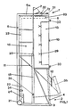
- the silo 1 shown in FIGS. 1 and 2 has a stand frame 2.
- the carriers 4 of this stand frame 2 extend in a manner known per se from a floor frame 3 upwards.
- the silo 1 has a bottom 11 which runs obliquely from top to bottom to the longitudinal axis of the silo.
- This floor 11 extends at an angle to the longitudinal axis of the silo from a side wall of the silo 1 to an outlet 12 which, as shown, is arranged outside the stand frame 2. Due to its arrangement, this outlet 12 is directly accessible from the outside, so that downstream systems or corresponding conveyors can be connected directly to this outlet 12.
- two parallel rails 6 extend upwards from the base frame 3. These rails 6 are extended beyond the upper end wall 17 of the silo 1 and a pivotable receiving eye 7 is mounted between these sections 6a. Its fulcrum lies in the silo axis of gravity of the standing silo. When setting up, the rail 6 can thus detach itself from the vehicle frame in the upper area and the silo tilts into the vertical position. In the lying transport position on the vehicle, the eyelet folds away and assumes the outer center position prescribed by the DIN regulation for hook deposit devices.
- a tube or a roller bearing is provided in the section of the base frame 3 opposite the outlet 12.
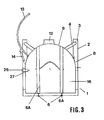
- FIG. 3 shows the cross section 16 of the silo section 15 lying above the floor 11.
- This cross section 16 has the shape of a rectangle, one side of which is replaced by an arc. In the illustrated embodiment, this arc is a circular arc section.
- the silo 1 has the shape of a parallelepiped box, which is closed off by a vault that lies when lying Silo is on top.
- the side wall section 8 is a curved, in particular circular cylindrical side wall section.
- the filling opening 9 is formed in this side wall section. The filling opening 9 is aligned with the outlet 12.
- FIGS. 1 and 2 The embodiment described above and shown in FIGS. 1 and 2 is used for the transport of a coarse-grained hard material, such as sand or gravel.
- a coarse-grained hard material such as sand or gravel.
- the lying silo 1 can be filled by means of a loading device.
- the silo 1 is used only for the transport of fine, powdery materials, the filling opening 9 with a flap 13 is not provided.
- the silo 1 is then equipped with a blowing system. Two embodiments of this blowing system are shown in Figures 1 and 2.
- a blow line 18 is formed in the carrier 4 of the stand frame 2.
- This blow line 18 has a blow line connection 26.
- the blow line 18 opens into the silo 1 at 20 above the base 11.
- This deep-lying mouth 20 leads to an operation in which the material is blown through the material layer that is formed in the silo 1 when it is blown in.
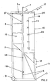
- a vent line 22 is provided for venting, the mouth 23 of which lies in the region of the upper end wall 17 of the silo 1.
- the vent line 22 extends downward out of the silo 1 and opens into a water tank 24, which serves as a dust filter.
- the section of the vent line 22 extending out of the silo 1 can also be in one of the supports 4 of the stand frame 2 be trained.
- a blow line 25 is formed, which has a connection 26.
- the blow line 25 extends, as shown, into the silo 1 up to the area of the upper end wall 17.
- the blow line has a plurality of orifices 27 which are spaced one above the other.
- an overpressure or expansion valve 28 is provided for ventilation in the region of the upper end wall 17.
- the two loading systems as shown in FIGS. 1 and 2, can be combined with one another.
- devices to be described are also provided, which of course can also be installed in the embodiment shown in FIG. 2.
- suction line connections 30 and 31 are arranged at a distance from one another in the upper end wall 17 of the silo 1.
- suction line connections 32 and 33 can only be arranged at an axial distance from one another in the side wall of the silo 1, or can be provided together with the suction line connections 30 and 31 in the upper front wall 17. These suction line connections can be blocked.
- a suction line can be connected to the suction line connection 30 that can be led to a point where material is to be extracted.
- the suction line connection 31 is connected to a suction line which leads to a blower which is arranged, for example, in a vehicle.
- silo 1 serves as a separator. So that the silo can be used horizontally as a separator, two lockable suction line connections 32 and 33 are provided in the vertical line of the curved side wall section 8 in the illustrated embodiment.
- a shut-off valve 34 is installed in the vent line 22 for the operation of the silo 1 as a separator.
- a T-piece 35 is connected to the outlet 12, through which a conveying air flow is guided.
- an overpressure is entered into the silo 1, for example, via the openings 27 (FIG. 2) of the blow line.
- the vent 28 is designed as an expansion flap in this case.
Landscapes
- Engineering & Computer Science (AREA)
- Mechanical Engineering (AREA)
- Filling Or Emptying Of Bunkers, Hoppers, And Tanks (AREA)
- Storage Of Harvested Produce (AREA)
- Basic Packing Technique (AREA)
Priority Applications (1)
| Application Number | Priority Date | Filing Date | Title |
|---|---|---|---|
| AT89730159T ATE82929T1 (de) | 1989-02-16 | 1989-07-11 | Silo fuer fliessfaehige stoffe. |
Applications Claiming Priority (2)
| Application Number | Priority Date | Filing Date | Title |
|---|---|---|---|
| DE3904955A DE3904955A1 (de) | 1989-02-16 | 1989-02-16 | Container-silo fuer fliessfaehige stoffe |
| DE3904955 | 1989-02-16 |
Publications (2)
| Publication Number | Publication Date |
|---|---|
| EP0382995A1 EP0382995A1 (de) | 1990-08-22 |
| EP0382995B1 true EP0382995B1 (de) | 1992-12-02 |
Family
ID=6374377
Family Applications (1)
| Application Number | Title | Priority Date | Filing Date |
|---|---|---|---|
| EP89730159A Expired - Lifetime EP0382995B1 (de) | 1989-02-16 | 1989-07-11 | Silo für fliessfähige Stoffe |
Country Status (3)
| Country | Link |
|---|---|
| EP (1) | EP0382995B1 (enExample) |
| AT (1) | ATE82929T1 (enExample) |
| DE (2) | DE3904955A1 (enExample) |
Families Citing this family (1)
| Publication number | Priority date | Publication date | Assignee | Title |
|---|---|---|---|---|
| FI20021614A7 (fi) * | 2002-09-10 | 2004-03-11 | Fiateck Oy | Säilytysväline ja sen käyttö |
Family Cites Families (6)
| Publication number | Priority date | Publication date | Assignee | Title |
|---|---|---|---|---|
| CH12351A (de) * | 1896-06-11 | 1896-11-30 | August Kind | Lagerbehälter für Schüttgüter |
| US1728197A (en) * | 1927-05-24 | 1929-09-17 | Fairfield Eng Co | Storing material |
| DE2148048C3 (de) * | 1971-09-25 | 1980-11-27 | Gebr. Knauf Westdeutsche Gipswerke, 8715 Iphofen | Geschlossener Behälter für schütt- oder fließfähiges Gut mit einem Untergestell |
| DE2441911A1 (de) * | 1974-09-02 | 1976-03-18 | Zyklos Metallbau Kg | Silo fuer schuettgueter |
| DE3205564C2 (de) * | 1982-02-17 | 1984-02-09 | Eugen Dietterle KG, Gips- und Sägewerk, 7033 Herrenberg | Silo für Trockengips und andere Trockenmörtel |
| DE8704215U1 (de) * | 1987-03-20 | 1987-05-07 | Silo Estrich GmbH + Co Vertriebs KG, 96146 Altendorf | Vorrichtung zum Transport und zur baustellenseitigen Bevorratung von schüttgutartigen Baustoffen |
-
1989
- 1989-02-16 DE DE3904955A patent/DE3904955A1/de active Granted
- 1989-07-11 DE DE8989730159T patent/DE58902901D1/de not_active Expired - Fee Related
- 1989-07-11 EP EP89730159A patent/EP0382995B1/de not_active Expired - Lifetime
- 1989-07-11 AT AT89730159T patent/ATE82929T1/de not_active IP Right Cessation
Also Published As
| Publication number | Publication date |
|---|---|
| DE3904955A1 (de) | 1990-08-23 |
| EP0382995A1 (de) | 1990-08-22 |
| DE58902901D1 (de) | 1993-01-14 |
| ATE82929T1 (de) | 1992-12-15 |
| DE3904955C2 (enExample) | 1992-04-09 |
Similar Documents
| Publication | Publication Date | Title |
|---|---|---|
| EP0937004B1 (de) | Vorrichtung und verfahren zum pneumatischen fördern pulverförmiger stoffe | |
| DE1431356A1 (de) | Entleerungsvorrichtung fuer Behaelter fuer pulverfoermige oder koernige Stoffe | |
| DE8621956U1 (de) | Vorrichtung zum Füllen von in horizontaler Richtung an wechselnder Stelle befindliche, nach oben offene Einfüllstutzen | |
| EP0065624B1 (de) | Verfahren zum Befüllen von Silofahrzeugbehältern | |
| DE2745748A1 (de) | Vorrichtung zum entfernen koerniger materialien aus einem unter druck stehenden raum | |
| EP0382995B1 (de) | Silo für fliessfähige Stoffe | |
| DE4240014C2 (de) | Beladungsvorrichtung | |
| DE2735180A1 (de) | Verfahren und vorrichtung zur abgabe eines fluidisierbaren feinzerteilten materials aus einem behaelter | |
| DE3322698A1 (de) | Geschlossener behaelter fuer schuett- oder fliessfaehiges gut, insbesondere baustoff | |
| EP0369358A1 (de) | Behälterfahrzeug | |
| DE3305130A1 (de) | Muellsammelfahrzeug | |
| DE437516C (de) | Geschlossener Eisenbahnwagen | |
| EP0741089A1 (de) | Tank mit oben angeordneter Befüll- und Entleereinrichtung | |
| CH475153A (de) | Container mit Entleerungsvorrichtung, für den Transport von staubförmigem oder stückigem Gut | |
| DD230732A3 (de) | Transportbehaelter fuer faesser mit radioaktiven abfaellen | |
| EP1997753B1 (de) | Verfahren und Anordnung zum Entladen von rieselfähigen Medien aus Tanklastzügen | |
| DE7435968U (de) | Container für körniges und staubförmiges gut | |
| DE3447125A1 (de) | Grossbehaelter | |
| DE3316803A1 (de) | Untertagetankwagen | |
| DE2233420C3 (de) | Container für feuchtigkeitsempfindliches Schüttgut | |
| AT379351B (de) | Pneumatisch fuellbarer behaelter aus flexiblem, luftdichtem material | |
| DE2248154C3 (de) | Vorrichtung zur Entleerung von Schüttgut aus Transport-Containern | |
| DE1556756C3 (de) | Transportbehälter für Schüttgut | |
| DE8814399U1 (de) | Vorabscheider mit Ringspülleitungen zur Abscheidung und Ausspülung von feinstfaserförmigen Schadstoffen | |
| DE1178362B (de) | Ortsbewegliches, pneumatisches Entladegeraet |
Legal Events
| Date | Code | Title | Description |
|---|---|---|---|
| PUAI | Public reference made under article 153(3) epc to a published international application that has entered the european phase |
Free format text: ORIGINAL CODE: 0009012 |
|
| AK | Designated contracting states |
Kind code of ref document: A1 Designated state(s): AT BE DE FR GB IT NL SE |
|
| 17P | Request for examination filed |
Effective date: 19901023 |
|
| 17Q | First examination report despatched |
Effective date: 19910820 |
|
| GRAA | (expected) grant |
Free format text: ORIGINAL CODE: 0009210 |
|
| AK | Designated contracting states |
Kind code of ref document: B1 Designated state(s): AT BE DE FR GB IT NL SE |
|
| PG25 | Lapsed in a contracting state [announced via postgrant information from national office to epo] |
Ref country code: IT Free format text: LAPSE BECAUSE OF FAILURE TO SUBMIT A TRANSLATION OF THE DESCRIPTION OR TO PAY THE FEE WITHIN THE PRE;WARNING: LAPSES OF ITALIAN PATENTS WITH EFFECTIVE DATE BEFORE 2007 MAY HAVE OCCURRED AT ANY TIME BEFORE 2007. THE CORRECT EFFECTIVE DATE MAY BE DIFFERENT FROM THE ONE RECORDED.SCRIBED TIME-LIMIT Effective date: 19921202 Ref country code: GB Effective date: 19921202 Ref country code: BE Effective date: 19921202 Ref country code: SE Effective date: 19921202 Ref country code: NL Effective date: 19921202 Ref country code: FR Effective date: 19921202 |
|
| REF | Corresponds to: |
Ref document number: 82929 Country of ref document: AT Date of ref document: 19921215 Kind code of ref document: T |
|
| REF | Corresponds to: |
Ref document number: 58902901 Country of ref document: DE Date of ref document: 19930114 |
|
| EN | Fr: translation not filed | ||
| NLV1 | Nl: lapsed or annulled due to failure to fulfill the requirements of art. 29p and 29m of the patents act | ||
| GBV | Gb: ep patent (uk) treated as always having been void in accordance with gb section 77(7)/1977 [no translation filed] |
Effective date: 19921202 |
|
| PG25 | Lapsed in a contracting state [announced via postgrant information from national office to epo] |
Ref country code: AT Effective date: 19930711 |
|
| PLBE | No opposition filed within time limit |
Free format text: ORIGINAL CODE: 0009261 |
|
| STAA | Information on the status of an ep patent application or granted ep patent |
Free format text: STATUS: NO OPPOSITION FILED WITHIN TIME LIMIT |
|
| 26N | No opposition filed | ||
| PGFP | Annual fee paid to national office [announced via postgrant information from national office to epo] |
Ref country code: DE Payment date: 19960209 Year of fee payment: 7 |
|
| PG25 | Lapsed in a contracting state [announced via postgrant information from national office to epo] |
Ref country code: DE Effective date: 19971101 |