EP0382201B1 - Korona-Entladungs-Vorrichtung - Google Patents
Korona-Entladungs-Vorrichtung Download PDFInfo
- Publication number
- EP0382201B1 EP0382201B1 EP90102442A EP90102442A EP0382201B1 EP 0382201 B1 EP0382201 B1 EP 0382201B1 EP 90102442 A EP90102442 A EP 90102442A EP 90102442 A EP90102442 A EP 90102442A EP 0382201 B1 EP0382201 B1 EP 0382201B1
- Authority
- EP
- European Patent Office
- Prior art keywords
- engaging
- discharging device
- cover
- corona discharging
- corona
- Prior art date
- Legal status (The legal status is an assumption and is not a legal conclusion. Google has not performed a legal analysis and makes no representation as to the accuracy of the status listed.)
- Expired - Lifetime
Links
- 238000007599 discharging Methods 0.000 title claims description 50
- 230000001105 regulatory effect Effects 0.000 claims description 17
- 230000000694 effects Effects 0.000 claims description 2
- 239000011810 insulating material Substances 0.000 description 4
- 238000000034 method Methods 0.000 description 4
- 238000004140 cleaning Methods 0.000 description 3
- 238000010276 construction Methods 0.000 description 3
- 230000005489 elastic deformation Effects 0.000 description 3
- 238000011161 development Methods 0.000 description 2
- 230000018109 developmental process Effects 0.000 description 2
- 230000000737 periodic effect Effects 0.000 description 2
- 230000003044 adaptive effect Effects 0.000 description 1
- 238000005452 bending Methods 0.000 description 1
- 230000000903 blocking effect Effects 0.000 description 1
- 230000000295 complement effect Effects 0.000 description 1
- 239000004020 conductor Substances 0.000 description 1
- 238000011109 contamination Methods 0.000 description 1
- 230000001747 exhibiting effect Effects 0.000 description 1
- 230000005923 long-lasting effect Effects 0.000 description 1
- 239000002184 metal Substances 0.000 description 1
- 239000011347 resin Substances 0.000 description 1
- 229920005989 resin Polymers 0.000 description 1
- 230000000717 retained effect Effects 0.000 description 1
- 230000000087 stabilizing effect Effects 0.000 description 1
- 210000005182 tip of the tongue Anatomy 0.000 description 1
Images

Classifications
-
- H—ELECTRICITY
- H01—ELECTRIC ELEMENTS
- H01T—SPARK GAPS; OVERVOLTAGE ARRESTERS USING SPARK GAPS; SPARKING PLUGS; CORONA DEVICES; GENERATING IONS TO BE INTRODUCED INTO NON-ENCLOSED GASES
- H01T19/00—Devices providing for corona discharge
-
- G—PHYSICS
- G03—PHOTOGRAPHY; CINEMATOGRAPHY; ANALOGOUS TECHNIQUES USING WAVES OTHER THAN OPTICAL WAVES; ELECTROGRAPHY; HOLOGRAPHY
- G03G—ELECTROGRAPHY; ELECTROPHOTOGRAPHY; MAGNETOGRAPHY
- G03G15/00—Apparatus for electrographic processes using a charge pattern
- G03G15/02—Apparatus for electrographic processes using a charge pattern for laying down a uniform charge, e.g. for sensitising; Corona discharge devices
- G03G15/0291—Apparatus for electrographic processes using a charge pattern for laying down a uniform charge, e.g. for sensitising; Corona discharge devices corona discharge devices, e.g. wires, pointed electrodes, means for cleaning the corona discharge device
Definitions
- the present invention is directed to a corona discharging device for use with an image forming apparatus such as a copying machine or the like.
- Such an image forming apparatus like a copying machine comprises a corona discharging device for electrifying a photosensitive body.
- a corona discharging device for electrifying a photosensitive body.
- a corona discharging device of the so-called scorotron type is used in which a mesh-like grid plate defined as a control grid is interposed between the photosensitive body and a corona wire.
- the grid plate is typically mounted on the corona discharging device and is so constructed as to be attachable to and detachable from the copying machine body together with the corona discharging device.
- a long lasting use of the corona discharging device causes adhesion of foreign matters to the corona wire or contamination in the interior of a shield case, which in turn require periodic cleaning.
- an easier work needs removal of the grid plate attached to the corona discharging device.
- the grid plate removed has to be, as a matter of course, remounted on the corona discharging device.
- end blocks for holding the corona wire are fixedly provided at both ends of the corona discharging device, engaging members integrally stand erect on the end blocks.
- One of the engaging members is arranged to be elastically deformable, whereby the engaging members engage with slits conceived as engaged parts of the grid plate.
- an engagement portion formed on a U-shaped spring member detachably mounted on a discharging body engages with a slit formed in the grid plate.
- the first of the prior art corona discharging devices presents the following problems.
- the grid plate is stretched with a tension due to the elasticity of one of the engaging members, and hence a distance between the engaging members disposed at both ends of the corona discharging device in the longitudinal direction has to be longer than between the slits formed on both ends of the grid plate.
- the engagement portion formed by an elastic protrusion has to be deformed beforehand, or alternatively the grid plate is required to be pulled inwards to the greatest possible extent. Therefore, the attachment thereof is quite troublesome.
- dismounting the grid plate involves operations reversed to the above, so that the troublesome situation is the same.
- the second of the prior art corona discharging devices is attended with the following problems. It is difficult to insert the U-shaped spring member into the discharging body, against the resilient force thereof. Even if inserted, the spring member has a tendency to spring out of the discharging body due to its resilient force. In addition, the configuration of the corona discharging device becomes intricate, and its assembly is also troublesome.
- the document US-A-4 550 253 discloses a corona charger of scorotron type wherein a corona wire is detachably secured to a base frame made of insulating material and a control grid is also detachably secured to a grid frame made of insulating material.
- the corona wire is secured to a base frame so that it is stretched out resiliently between two end portions.
- a grid frame provided to cover the corona wire, can be detachably fixed to the base frame by means of a pair of screws.
- a slide plate At one end of the grid frame, there is provided a slide plate which can be slidably moved in a longitudinal direction. For this purpose, the slide plate is biased by means of a coiled spring.
- a control grid is provided which is fixed to the grid frame by means of openings co-operating with projections of the grid frame.
- the proper function of this conventional device depends on a sufficient bias force of the coiled spring biasing the slide plate. If this spring is broken or worn out, the proper positioning and function of the control grid cannot be ensured.
- the object underlying the present invention is to provide a corona discharging device which is capable of facilitating the attachment and detachment of a grid plate with a simple construction.
- a corona discharging device comprising: a body; a corona wire stretched within the body; a control grid having receiving portions formed at two ends thereof, for covering at least a part of the corona wire; engaging members engaging with the receiving portions of the control grid; and support members for supporting the engaging members, at least one of the support members being detachably attached to the body, which corona discharging device is characterized in that said at least one support member is arranged so that, when being attached, an end of said support member on the side of the control grid abuts upon a part of the body and that the support member is rotated with the end thereof serving as a fulcrum, and in that lock means are provided for locking said one of the support members when it is attached to the body.
- a corona discharging device comprising: a shield case; end blocks formed with openings and provided at both ends of the shield case; cover members detachably mounted on the end blocks to cover the openings; a corona wire stretched between the end blocks; and a control grid, formed at its both ends with receiving portions, for covering at least a part of the corona wire, wherein at least one of engaging members engaging with the receiving portions is provided on one of the cover members and at least one of the engaging members is elastically deformable in a stretching direction of the control grid, which corona discharging device is characterized in that said corona discharging device further comprises lock means for locking the cover member, when being set in the opening of the end block wherein said lock means consists of a second engaging member provided on the cover member and a second receiving portion formed in the end block, arranged to effect locking by abutting an inner end of the cover member against an inner end of the end block and by engaging the second engaging member with the second
- the numeral 1 designates a corona discharging device mainly comprising the following components: a shield case 2; end blocks 3; a corona wire 4; a cover 6 constituting a support member; and a grid plate 20 which forms a control grid.
- the shield case 2 is formed of a conductive material to assume a substantially C-like configuration, wherein the shield case may have sidewalls 2a and 2b and a bottom wall 2c.
- the end blocks 3 are provided at both ends of the shield case 2 .
- the corona wire 4 Stretched between the end blocks 3 is the corona wire 4 for electrifying a photosensitive body (not illustrated) with a predetermined tension by proper means like machine screws 25.
- the corona wire 4 may pass through suitable apertures in respective end walls of the end blocks 3 and is electrically connected to a connector terminal 26 provided on an end surface of one of the end blocks 3 by known means.
- a cover 6 made of an insulating material is generally attached.
- the cover 6 is provided with a stopper 7 forming a second engaging member, the stopper 7 protruding therefrom, as shown in Fig. 1.
- the end block 3 corresponding thereto is formed with a notch 8 conceived as a receiving portion to be engaged with the stopper 7.
- the stopper 7 is inserted and fitted into the notch 8, thereby engaging the cover 6 with the end block 3. It is useful to have two pairs of notches 8 and stoppers 7, especially when they are provided in the sides of the end blocks 3; however, one pair of one stopper 7 and a complementary notch 8 may be sufficient, especially when provided in the end wall of the end block 3.
- a substantially central portion of the cover 6 is provided with an engaging member 11 consisting of a base 9 having a thickness smaller than that of the cover 6 and of a hook-like portion 10 formed in continuation of the base 9.
- the hook-like portion 10 is relatively and sufficiently thin to be elastically deformed by a force acting in a direction as indicated by an arrow A in Fig. 1 and Fig. 2.
- a height regulating member 13 for regulating the height of the grid plate 20 is provided in continuation of the cover 6 on one side of a discharging region, projecting from an edge of the cover 6. Namely, the height regulating member 13 serves to keep constant a spacing between a surface of the photosensitive body and the grid plate 20.
- the grid plate 20 consists mainly of a mesh 21 and a frame 22.
- Slits 23 serving as receiving portions to be engaged with the hook-like portion 10 are formed in both ends of the frame 22 in the longitudinal direction thereof.
- the respective slit 23 is caught by the hook-like portion 10 of the engaging member 11, whereby the grid plate 20 is held by the cover 6, which in turn is engaged with the end block 3.
- Both ends of the frame 22 in the longitudinal direction abut against the height regulating member 13, thereby regulating the height and the spacing of the grid plate 20 with respect to the shield case 2.
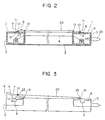
- the first cover 6 is mounted on the first end block 3 depicted at an upper right portion in Figs. 2 and 3 by engaging the stopper 7 provided on the first cover 6 with the notch 8 formed in the right end block 3. Subsequent to this step, the slit 23 formed at the right end of the grid plate 20 is caught by the hook-like portion 10 of the right engaging member 11 provided on the first cover 6 attached to the right end block 3. The slit 23 formed in the left end of the grid plate 20 is caught by the hook-like portion 10 of the left engaging member 11 provided on the second cover 6. At this time, the second cover 6 is not yet engaged with the left end block 3 as shown in Figs. 2 and 3. Thereafter, the second cover 6 is attached to the left end block 3 as shown in Fig.
- the second cover 6 is rotated in a direction indicated by an arrow B to engage the stopper 7 thereof with the notch 8 of the left end block 3 to assume a configuration depicted in Fig. 3, wherein the fulcrum is the end of the second cover 6 mounted on the left end block 3 on the side of the height regulating member 13.
- the two hook-like portions 10 of the two engaging members 11 provided on the two covers 6 are elastically deformed in such a direction as to gradually narrow a spacing therebetween in accordance with the length of the grid plate 20.
- the two engaging members 11 provided with the hook-like portions 10 undergo the elastic deformation corresponding to the length of the grid plate 20, and the lower part of the frame 22 of the grid plate 20 abuts against the two height regulating members 13, thus regulating the height and spacing of the grid plate 20.
- the grid plate 20 can be stretch-retained with a proper tension.
- the workability be improved by removing the grid plate 20.
- the reversed operations are performed. That is, the grid plate 20 can be removed simply by dismounting one cover 6 from the respective end block 3.
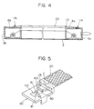
- FIG. 4 Another embodiment of the invention will be explained with reference to Fig. 4.
- the arrangement of this further embodiment differs from the preceding embodiment in that one engaging member is attached to the end block instead of the cover, and the other engaging member has no elasticity.
- the first cover 6a mounted on the right end block 3a includes only the height regulating member 13 of the grid plate 20 but does not have any stopper and notch for engagement, Rather, in this embodiment, the right engaging member 11a for holding the right end of the grid plate 20 is provided on the right end block 3a fixed to the shield case 2.
- the configuration of the right engaging member 11a is identical with that shown in the previous embodiment, and the explanation is therefore omitted.
- the second cover 6b fitted to the left end block 3b is provided with a left engaging member 11b having no elasticity.
- a slit formed in the right end of the grid plate 20 has to be engaged with the right engaging member 11a provided on the right end block 3a.
- the second cover 6b is taken off from the left end block 3b, in which state a slit formed in the left end of the grid plate 20 is engaged with the left engaging member 11b.
- the second cover 6b is mounted on the left end block 3b in the same manner as that of the embodiment discussed above.
- the grid plate 20 can be stretched with an adequate tension, because one engaging member has the necessary elasticity.
- FIG. 5 there is shown still another embodiment of the engaging member according to the present invention.
- the above-described two embodiments adopt an arrangement where the engaging member is formed integrally with the cover or the end block. However, in this embodiment, an engaging member separate from the cover is attached thereto.
- an engaging member 110 involves the use of a leaf spring formed by bending, e.g., a thin metal plate. Describing the configuration in greater detail, the engaging member 110 includes a hook portion 100, corresponding to the hook-like portion 10 used in the previous embodiments, and a base plate 90 corresponding to the base 9. The engaging member 110 is mounted on a cover 60 in the following manner.
- the base plate 90 is notched to form a tongue piece 91.
- a pin 61 standing upright on the cover 60 is fitted into the notched portion of the base plate 90, in which case the tongue piece 91 abuts against the pin 61 from the opposite side to the grid plate 20.
- the pin 61 is formed with a notch 62 into which the tip of the tongue piece 91 is inserted, thus preventing the engaging member 110 from coming off upwards in Fig. 5.
- the tongue piece 91 also has a spring property adaptive more elastically to a pulling force acting in a direction indicated by an arrow C in Fig. 5.
- the shield case 2 is formed to assume a substantially C-like configuration in section, wherein the corona wire 4 may be surrounded by three wall elements 2a, 2b and 2c in Fig. 1.
- the three wall elements are not necessarily provided. There may be adopted a combination of the wall elements 2a and 2b, or 2a and 2c; or one wall element, e.g., 2c may be sufficient.
- the configuration of the shield case 2 may be properly selected to be adapted to the respective type of a copying machine.
- This type of process unit is an image forming unit including a photosensitive body, an electrifying part, a developing part and a cleaning part.
- a casing for accommodating these components is typically formed of a resin.
- a shield case of the electrifying part and end blocks are formed integrally with the resinous casing, and a conductive plate is installed on the rear surface opposite to a discharge opening formed in the side of the photosensitive body.
- the present invention can be applied even to the thus constructed process units on condition that at least one end block is fitted with a cover for blocking the opening.
- the above embodiments deal with an arrangement where the height regulating member 13 of the grid plate 20 is provided in continuation of the respective cover 6.
- the height regulating member 13 may be attached to the end block or formed integrally with the end block.
- the configuration of the height regulating member 13 can be varied as the case may be.
Landscapes
- Physics & Mathematics (AREA)
- Engineering & Computer Science (AREA)
- Plasma & Fusion (AREA)
- General Physics & Mathematics (AREA)
- Electrostatic Charge, Transfer And Separation In Electrography (AREA)
Claims (11)
- Koronaentladungsvorrichtung, umfassend:- einen Körper (2);- einen Koronadraht (4), der im Inneren des Körpers (2) gespannt ist;- ein Steuergitter (20), das an zwei Enden desselben ausgebildete Aufnahmebereiche (23) aufweist und zum Überdecken wenigstens eines Teils des Koronadrahts (4) dient;- Eingriffselemente (11, 11a, 11b, 110), die mit den Aufnahmebereichen (23) des Steuergitters (20) in Eingriff stehen; und- Halterungselementen (6, 6a, 6b, 60) zum Haltern der Eingriffselemente (11, 11a, 11b, 110), wobei wenigstens eines (6, 6b, 60) der Halterungselemente an dem Körper (2) lösbar angebracht ist,dadurch gekennzeichnet,
daß das wenigstens eine Halterungselement derart ausgebildet ist, daß es, wenn es angebracht wird, ein Ende des Halterungselementes (6, 6b, 60) auf der Seite des Steuergitters (20) gegen ein Teil des Körpers (2) anliegt und das Halterungselement (6, 6b, 60) verschwenkt wird, wobei das Ende davon als Schwenkpunkt dient,
und daß eine Verriegelungseinrichtung (7, 8) zum Verriegeln des genannten einen Halterungselements (6, 6b, 60) vorgesehen ist, wenn dieses an dem Körper (2) angebracht ist. - Koronaentladungsvorrichtung nach Anspruch 1,
dadurch gekennzeichnet,
daß wenigstens eines (11, 11a, 110) der Eingriffselemente (11, 11a, 11b, 110) in einer Spannrichtung des Steuergitters (20) elastisch verformbar ist. - Koronaentladungsvorrichtung nach Anspruch 1 oder 2,
dadurch gekennzeichnet,
daß das Eingriffselement (11, 11b) integral mit dem Halterungselement (6, 6b) ausgebildet ist. - Koronaentladungsvorrichtung nach Anspruch 1 oder 2,
dadurch gekennzeichnet,
daß das Eingriffselement (110) ein an dem Halterungselement (60) angebrachtes Blattfederelement ist. - Koronaentladungsvorrichtung nach einem der Ansprüche 1 bis 4,
dadurch gekennzeichnet,
daß das Halterungselement (6, 6a, 6b, 60) ein Abdeckelement zum Abdecken eines Endes des Körpers (2) ist. - Koronaentladungsvorrichtung nach einem der Ansprüche 1 bis 5,
dadurch gekennzeichnet,
daß das Halterungselement (6, 6a, 6b, 60) ein Höhenregulierelement (13) zum Regulieren der Höhe des Steuergitters (20) aufweist. - Koronaentladungsvorrichtung nach einem der Ansprüche 1 bis 6,
dadurch gekennzeichnet,
daß die Verriegelungseinrichtung (7, 8) aus einem an dem Halterungselement (6, 6b, 60) vorgesehenen, zweiten Eingriffselement (7) und aus einem in dem Körper (2) ausgebildeten, zweiten Aufnahmebereich (8) gebildet ist,
und daß das Halterungselement (6, 6b, 60) derart ausgebildet ist, daß es sich dadurch an dem Körper (2) verriegeln läßt, daß man das zweite Eingriffselement (7) mit dem zweiten Aufnahmebereich (8) in Eingriff bringt. - Koronaentladungsvorrichtung, umfassend:- ein Abschirmgehäuse (2);- Endblöcke (3, 3a, 3b), die mit Öffnungen (5) ausgebildet sind und an beiden Enden des Abschirmgehäuses (2) vorgesehen sind;- Abdeckelemente (6, 6b, 60), die an den Endblökken (3, 3a, 3b) lösbar angebracht sind zum Abdecken der Öffnungen;- einen zwischen den Endblöcken (3, 3a, 3b) gespannten Koronadraht (4); und- ein an seinen beiden Enden mit Aufnahmebereichen (23) ausgebildetes Steuergitter (20) zum Überdecken wenigstens eines Teils des Koronadrahts (4), wobei wenigstens eines (11, 11b, 110) der mit den Aufnahmebereichen (23) in Eingriff stehenden Eingriffselemente (11, 11a, 11b, 100) an einem (6, 6b, 60) der Abdeckelemente vorgesehen ist und wenigstens eines der Eingriffselemente (11, 11a, 110) in einer Spannrichtung des Steuergitters (20) elastisch verformbar ist,dadurch gekennzeichnet,
daß die Koronaentladungsvorrichtung weiterhin eine Verriegelungseinrichtung (7, 8) zum Verriegeln eines Abdeckelements (6, 6b, 60) aufweist, wenn dieses in die Öffnung des Endblocks (3, 3b) gesetzt ist, wobei die Verriegelungseinrichtung (7, 8) aus einem an dem Abdeckelement (6, 6b, 60) vorgesehenen, zweiten Eingriffselement (7) und aus einem in dem Endblock (3, 3b) ausgebildeten, zweiten Aufnahmebereich (8) besteht und dadurch zur Bewerkstelligung einer Verriegelung ausgelegt ist, daß ein inneres Ende des Abdeckelements (6, 6b, 60) an einem inneren Ende des Endblocks (3, 3b) in Anlage gebracht wird und das zweite Eingriffselement (7) mit dem zweiten Aufnahmebereich (8) in Eingriff gebracht wird, wobei das Abdeckelement (6, 6b, 60) mit seinem anliegenden Teil als Schwenkpunkt dienend verschwenkt wird. - Koronaentladungsvorrichtung nach Anspruch 8,
dadurch gekennzeichnet,
daß das Eingriffselement (11, 11b) mit dem Abdeckelement (6, 6b) integral ausgebildet ist. - Koronaentladungsvorrichtung nach Anspruch 8,
dadurch gekennzeichnet,
daß das Eingriffselement (110) ein an dem Abdeckelement (60) angebrachtes Blattfederelement ist. - Koronaentladungsvorrichtung nach einem der Ansprüche 8 bis 10,
dadurch gekennzeichnet,
daß das Abdeckelement (6, 6a, 6b, 60) ein Höhenregulierelement (13) zum Regulieren der Höhe des Steuergitters (20) aufweist.
Applications Claiming Priority (2)
| Application Number | Priority Date | Filing Date | Title |
|---|---|---|---|
| JP1521189 | 1989-02-10 | ||
| JP15211/89 | 1989-02-10 |
Publications (3)
| Publication Number | Publication Date |
|---|---|
| EP0382201A2 EP0382201A2 (de) | 1990-08-16 |
| EP0382201A3 EP0382201A3 (de) | 1992-04-01 |
| EP0382201B1 true EP0382201B1 (de) | 1994-12-14 |
Family
ID=11882542
Family Applications (1)
| Application Number | Title | Priority Date | Filing Date |
|---|---|---|---|
| EP90102442A Expired - Lifetime EP0382201B1 (de) | 1989-02-10 | 1990-02-07 | Korona-Entladungs-Vorrichtung |
Country Status (3)
| Country | Link |
|---|---|
| US (1) | US5079668A (de) |
| EP (1) | EP0382201B1 (de) |
| DE (1) | DE69014926T2 (de) |
Families Citing this family (11)
| Publication number | Priority date | Publication date | Assignee | Title |
|---|---|---|---|---|
| US5216465A (en) * | 1990-03-19 | 1993-06-01 | Fuji Xerox Co., Ltd. | Print cartridge insertable into an image forming apparatus |
| DE4201899C2 (de) * | 1991-01-31 | 1996-04-11 | Minolta Camera Kk | Elektrophotographische Prozeßeinheit |
| US5324942A (en) * | 1992-12-17 | 1994-06-28 | Xerox Corporation | Tunable scorotron for depositing uniform charge potential |
| US5440375A (en) * | 1993-01-11 | 1995-08-08 | Mita Industrial Co., Ltd. | Corona discharger displacing mechanism and grid electrode positioning mechanism |
| JP3304209B2 (ja) * | 1994-09-14 | 2002-07-22 | シャープ株式会社 | 帯電装置 |
| JP3607531B2 (ja) * | 1999-05-28 | 2005-01-05 | シャープ株式会社 | 帯電装置 |
| US7136612B2 (en) * | 2004-07-26 | 2006-11-14 | Xerox Corporation | Connection assembly for a xerographic charging device |
| JP5181518B2 (ja) * | 2007-04-13 | 2013-04-10 | 株式会社リコー | スコロトロン帯電装置、プロセスカートリッジ及び画像形成装置 |
| JP4465379B2 (ja) * | 2007-11-02 | 2010-05-19 | シャープ株式会社 | 帯電装置及び本帯電装置を備えた画像形成装置 |
| JP5760582B2 (ja) * | 2011-03-28 | 2015-08-12 | 富士ゼロックス株式会社 | 帯電装置、画像形成装置及び電位制御板 |
| JP5915965B2 (ja) * | 2011-11-14 | 2016-05-11 | 富士ゼロックス株式会社 | 帯電装置および画像形成装置 |
Family Cites Families (7)
| Publication number | Priority date | Publication date | Assignee | Title |
|---|---|---|---|---|
| DE2915040A1 (de) * | 1978-04-14 | 1979-10-25 | Canon Kk | Verfahren zum herstellen und anbringen eines koronaentladers |
| JPS5511255A (en) * | 1978-07-11 | 1980-01-26 | Ricoh Co Ltd | Corona discharge device |
| JPS58159545U (ja) * | 1982-04-20 | 1983-10-24 | オリンパス光学工業株式会社 | コロナ帯電器 |
| US4603964A (en) * | 1984-10-22 | 1986-08-05 | Xerox Corporation | Photoreceptor charging scorotron |
| JPS6230268U (de) * | 1985-08-07 | 1987-02-23 | ||
| US4792680A (en) * | 1987-01-12 | 1988-12-20 | Xerox Corporation | Corona device having a beryllium copper screen |
| US4764675A (en) * | 1987-10-22 | 1988-08-16 | Xerox Corporation | Self-tensioning coronode structure |
-
1990
- 1990-02-02 US US07/473,926 patent/US5079668A/en not_active Expired - Lifetime
- 1990-02-07 EP EP90102442A patent/EP0382201B1/de not_active Expired - Lifetime
- 1990-02-07 DE DE69014926T patent/DE69014926T2/de not_active Expired - Fee Related
Also Published As
| Publication number | Publication date |
|---|---|
| EP0382201A3 (de) | 1992-04-01 |
| DE69014926D1 (de) | 1995-01-26 |
| EP0382201A2 (de) | 1990-08-16 |
| DE69014926T2 (de) | 1995-08-10 |
| US5079668A (en) | 1992-01-07 |
Similar Documents
| Publication | Publication Date | Title |
|---|---|---|
| EP0382201B1 (de) | Korona-Entladungs-Vorrichtung | |
| US4792680A (en) | Corona device having a beryllium copper screen | |
| US4725732A (en) | Pin corotron and scorotron assembly | |
| US4764675A (en) | Self-tensioning coronode structure | |
| EP0579185B1 (de) | Einheit enthaltend ein bildtragendes Bauteil | |
| JPH0782264B2 (ja) | コロナ放電器 | |
| US5844768A (en) | Scorotron type charging device with elevation suppression device for a grid plate | |
| US6249660B1 (en) | Imaging cartridge for use in an image forming apparatus including detachable electrode member | |
| US6070307A (en) | Edge cover | |
| JP2924082B2 (ja) | コロナ放電器の絶縁ブロック取り付け装置 | |
| JPH09269466A (ja) | 眼鏡に取り付ける遮光具及びそれを構成する部品 | |
| JP3212650B2 (ja) | 静電記録装置 | |
| JP2732657B2 (ja) | コロナ帯電装置 | |
| JP2861252B2 (ja) | スコロトロン帯電器のグリッド板位置出し装置 | |
| JPH06308800A (ja) | 帯電装置 | |
| KR100739692B1 (ko) | 화상형성장치 | |
| JPH06289736A (ja) | 転写装置 | |
| JPH0741005Y2 (ja) | 電子写真装置 | |
| JP3259607B2 (ja) | コロナ放電装置 | |
| JPH05303261A (ja) | スコロトロン帯電装置のグリッドテンション構造 | |
| KR930005371Y1 (ko) | 전자사진 복사기의 현상기 장,탈착장치 | |
| JPH04306677A (ja) | 画像形成装置 | |
| KR100615653B1 (ko) | 프로젝션 텔레비전의 램프하우징 설치구조 | |
| JPH0738919Y2 (ja) | コロナ帯電装置 | |
| JP3043472B2 (ja) | 除帯電装置 |
Legal Events
| Date | Code | Title | Description |
|---|---|---|---|
| PUAI | Public reference made under article 153(3) epc to a published international application that has entered the european phase |
Free format text: ORIGINAL CODE: 0009012 |
|
| AK | Designated contracting states |
Kind code of ref document: A2 Designated state(s): DE FR GB NL |
|
| 17P | Request for examination filed |
Effective date: 19901213 |
|
| PUAL | Search report despatched |
Free format text: ORIGINAL CODE: 0009013 |
|
| AK | Designated contracting states |
Kind code of ref document: A3 Designated state(s): DE FR GB NL |
|
| 17Q | First examination report despatched |
Effective date: 19930115 |
|
| GRAA | (expected) grant |
Free format text: ORIGINAL CODE: 0009210 |
|
| AK | Designated contracting states |
Kind code of ref document: B1 Designated state(s): DE FR GB NL |
|
| ET | Fr: translation filed | ||
| REF | Corresponds to: |
Ref document number: 69014926 Country of ref document: DE Date of ref document: 19950126 |
|
| PLBE | No opposition filed within time limit |
Free format text: ORIGINAL CODE: 0009261 |
|
| STAA | Information on the status of an ep patent application or granted ep patent |
Free format text: STATUS: NO OPPOSITION FILED WITHIN TIME LIMIT |
|
| 26N | No opposition filed | ||
| PGFP | Annual fee paid to national office [announced via postgrant information from national office to epo] |
Ref country code: GB Payment date: 19970129 Year of fee payment: 8 |
|
| PGFP | Annual fee paid to national office [announced via postgrant information from national office to epo] |
Ref country code: FR Payment date: 19970211 Year of fee payment: 8 |
|
| PGFP | Annual fee paid to national office [announced via postgrant information from national office to epo] |
Ref country code: DE Payment date: 19970214 Year of fee payment: 8 |
|
| PGFP | Annual fee paid to national office [announced via postgrant information from national office to epo] |
Ref country code: NL Payment date: 19970227 Year of fee payment: 8 |
|
| PG25 | Lapsed in a contracting state [announced via postgrant information from national office to epo] |
Ref country code: GB Free format text: LAPSE BECAUSE OF NON-PAYMENT OF DUE FEES Effective date: 19980207 |
|
| PG25 | Lapsed in a contracting state [announced via postgrant information from national office to epo] |
Ref country code: FR Free format text: THE PATENT HAS BEEN ANNULLED BY A DECISION OF A NATIONAL AUTHORITY Effective date: 19980228 |
|
| PG25 | Lapsed in a contracting state [announced via postgrant information from national office to epo] |
Ref country code: NL Free format text: LAPSE BECAUSE OF NON-PAYMENT OF DUE FEES Effective date: 19980901 |
|
| GBPC | Gb: european patent ceased through non-payment of renewal fee |
Effective date: 19980207 |
|
| NLV4 | Nl: lapsed or anulled due to non-payment of the annual fee |
Effective date: 19980901 |
|
| PG25 | Lapsed in a contracting state [announced via postgrant information from national office to epo] |
Ref country code: DE Free format text: LAPSE BECAUSE OF NON-PAYMENT OF DUE FEES Effective date: 19981103 |
|
| REG | Reference to a national code |
Ref country code: FR Ref legal event code: ST |