EP0381931B1 - Falzapparat mit Glattschnitteinrichtung - Google Patents
Falzapparat mit Glattschnitteinrichtung Download PDFInfo
- Publication number
- EP0381931B1 EP0381931B1 EP90100432A EP90100432A EP0381931B1 EP 0381931 B1 EP0381931 B1 EP 0381931B1 EP 90100432 A EP90100432 A EP 90100432A EP 90100432 A EP90100432 A EP 90100432A EP 0381931 B1 EP0381931 B1 EP 0381931B1
- Authority
- EP
- European Patent Office
- Prior art keywords
- folder
- cylinder
- blowing nozzles
- connection hole
- compressed air
- Prior art date
- Legal status (The legal status is an assumption and is not a legal conclusion. Google has not performed a legal analysis and makes no representation as to the accuracy of the status listed.)
- Expired - Lifetime
Links
Images
Classifications
-
- B—PERFORMING OPERATIONS; TRANSPORTING
- B65—CONVEYING; PACKING; STORING; HANDLING THIN OR FILAMENTARY MATERIAL
- B65H—HANDLING THIN OR FILAMENTARY MATERIAL, e.g. SHEETS, WEBS, CABLES
- B65H45/00—Folding thin material
- B65H45/12—Folding articles or webs with application of pressure to define or form crease lines
- B65H45/16—Rotary folders
- B65H45/162—Rotary folders with folding jaw cylinders
-
- B—PERFORMING OPERATIONS; TRANSPORTING
- B41—PRINTING; LINING MACHINES; TYPEWRITERS; STAMPS
- B41F—PRINTING MACHINES OR PRESSES
- B41F13/00—Common details of rotary presses or machines
- B41F13/54—Auxiliary folding, cutting, collecting or depositing of sheets or webs
- B41F13/56—Folding or cutting
- B41F13/60—Folding or cutting crosswise
-
- B—PERFORMING OPERATIONS; TRANSPORTING
- B65—CONVEYING; PACKING; STORING; HANDLING THIN OR FILAMENTARY MATERIAL
- B65H—HANDLING THIN OR FILAMENTARY MATERIAL, e.g. SHEETS, WEBS, CABLES
- B65H45/00—Folding thin material
- B65H45/12—Folding articles or webs with application of pressure to define or form crease lines
- B65H45/28—Folding in combination with cutting
Definitions
- the invention relates to a folder with a smooth cutting device consisting of two knife cylinders equipped with scissor cut knives, one of which is provided with puncture needles adjacent to its scissor cut knives for holding the sections and dips with a part of its circumference into a suction channel.
- a folder of this type is known for example from DE-A-30 30 706.
- Such arrangements can lead to malfunctions in that the sections needled onto the puncture needles are not pulled off the puncture needles reliably enough in the region of the suction channel. The consequence of this is that several sections come to lie on top of each other and the lower ones Sections are pushed further and further onto the pin needles.
- the measures according to the invention ensure that the cylinder containing the puncture needles and blowing nozzles is not unduly weakened.
- the measures according to the invention are therefore advantageous, in particular in the case of knife cylinders with a small diameter, and ensure that in the case of folding apparatuses for the production of small product formats, unnecessarily large cylinder diameters are not required.
- Another advantage of the measures according to the invention can be seen in the fact that air is fed into the suction duct through the blowing nozzles, so that the amount of air sucked in from outside and accordingly the air flow resulting outside the suction duct are reduced, so that even with a comparatively strong suction draft inside of the suction channel there is no disturbance of the folding products passing through the folding device and a high level of noise.
- the cylinder containing the blow nozzles can be provided with at least one radially opening connection bore connected to the blow nozzles and can be enclosed in the region of the connection bore by a stationary block connected by one to the compressed air line Supply channel is penetrated, the inner mouth of which is run over by the mouth of the connecting bore.
- the block can expediently be pivotable and fixable with respect to the axis of the associated knife cylinder. This makes it possible to easily set the angular range within which compressed air is applied to the blowing nozzles.
- a further advantageous measure can consist in the mouth of the supply channel ending in a control chamber which extends over a circumferential angle which corresponds approximately to the circumferential angle over which the suction duct extends.
- a sleeve containing the control chamber can advantageously be inserted into the block. This measure enables particularly simple manufacture.
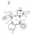
- the folding apparatus on which FIG. 1 is based contains a folding knife cylinder 1, the folding knife 2 of which with the Interacting jaws 3 of a jaw cylinder 4. This carries in the area between the jaws 3 scissors cutters 5 which cooperate with scissors cutters 7 arranged on an adjacent knife cylinder 6.
- the scissor cut knives 5 and 7 effect a smooth cut at the rear end of the products accommodated in the folding jaws 3.
- the products are delivered from the folding jaw cylinder 4 either to an adjacent belt guide or an adjacent paddle wheel.
- the stripe-shaped product sections resulting from the execution of the smooth cut are needled on the scissor cut knives 7 of the knife cylinder 6, that is to say set back in relation to them in the cylinder rotation direction, on the knife cylinder 6 stationary needle needles 8 and then suctioned off.
- a suction channel 9 is provided, into which the knife cylinder 6 is immersed with part of its circumference in such a way that the channel entrance is covered.
- the removal of the product sections from the puncture needles 8 is supported by measures on the cylinder side.
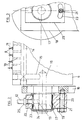
- the knife cylinder 6, as can best be seen from FIG. 2, is provided with the blowing needles 8 adjacent to the puncture needles 8. These are arranged in a row and in an alternating sequence with the puncture needles 8.
- the blow nozzles 10 are formed by radial bores with a small diameter of approximately 2 mm.
- the blowing nozzles 10 can be acted upon by compressed air as they pass through the circumferential area encompassed by the suction channel 9, as a result of which the product sections 11 needled on the pin needles 8, indicated by a dash-dotted line in FIG. 2, are lifted off the pin needles 8 and the suction channel 9 is fed with air.
- a compressed air line 12 is provided connected to a compressed air source, for example an internal compressed air network, which is connected via a rotating union to a bore system provided on the cylinder side, which leads from a radially opening connection bore 13 to the radial bores forming the blower nozzles 10.
- the radial bores forming the blowing nozzles start from an axial bore 14 which is continuous over the cylinder length and is closed in the region of the cylinder end faces and which is connected via a radial bore 15 which is likewise closed on the circumference to a central axial blind bore 16 which is closed on the end face and into which the radial connecting bore 13 opens.
- the knife cylinder 6 is provided with lateral journals 17 which are mounted in the associated frame walls 18. One of the journals 17 is provided with an extension extending beyond the associated frame wall 18 for receiving the connection bore 13 and the rotating union.
- the rotary feedthrough contains a block 20 which is provided with a bore 19 parallel to the cylinder and which is attached to the extension of the bearing pin 17 containing the connection bore 13.
- the block 20, which can be pivoted about the cylinder axis, can be connected to the adjacent frame wall 18 by means of a retaining screw 21 and can thus be secured against rotation.
- the block 20 is secured in the axial direction by clamping rings and spacer sleeves.
- the block 20 is provided with a radial bore forming a supply channel 22, to the circumferential end of which the compressed air line 12 connects and which passes through to the bore 19 parallel to the cylinder.
- the local inner mouth of the supply channel 22 is accordingly run over with each revolution of the knife cylinder 6 from the outer end of the connection bore 13, with the blowing nozzles 10 being pressurized with compressed air.
- a nipple 25 is provided for connecting the compressed air line 12 to the outer end of the radial bore 22 forming the supply channel.
- the retaining screw 21 is simply loosened and the block 20 is rotated accordingly. Accordingly, as can best be seen in FIG. 3, the latter is provided with an elongated hole 23 penetrated by the retaining screw 21 and concentric with the cylinder axis.
- a bushing 24 containing the bore 19 is inserted into the block 20 and has a circumferential recess 25 into which the radial bore forming the supply channel 22 runs.
- the recess 24 practically forms a control chamber for extending the compressed air supply to the blowing nozzles 10 over the diameter of the supply channel 22 corresponding angular range.
- the recess 24 accordingly extends over a circumferential angle which corresponds approximately to the circumferential angle within which the knife cylinder 6 dips into the intake duct 9.
Landscapes
- Engineering & Computer Science (AREA)
- Mechanical Engineering (AREA)
- Folding Of Thin Sheet-Like Materials, Special Discharging Devices, And Others (AREA)
Applications Claiming Priority (2)
| Application Number | Priority Date | Filing Date | Title |
|---|---|---|---|
| DE3903380A DE3903380A1 (de) | 1989-02-04 | 1989-02-04 | Falzapparat mit glattschnitteinrichtung |
| DE3903380 | 1989-02-04 |
Publications (3)
| Publication Number | Publication Date |
|---|---|
| EP0381931A2 EP0381931A2 (de) | 1990-08-16 |
| EP0381931A3 EP0381931A3 (de) | 1991-02-27 |
| EP0381931B1 true EP0381931B1 (de) | 1993-05-26 |
Family
ID=6373460
Family Applications (1)
| Application Number | Title | Priority Date | Filing Date |
|---|---|---|---|
| EP90100432A Expired - Lifetime EP0381931B1 (de) | 1989-02-04 | 1990-01-10 | Falzapparat mit Glattschnitteinrichtung |
Country Status (4)
| Country | Link |
|---|---|
| US (1) | US5049120A (enExample) |
| EP (1) | EP0381931B1 (enExample) |
| JP (1) | JP2771299B2 (enExample) |
| DE (2) | DE3903380A1 (enExample) |
Families Citing this family (10)
| Publication number | Priority date | Publication date | Assignee | Title |
|---|---|---|---|---|
| DE3904076A1 (de) * | 1989-02-11 | 1990-08-16 | Frankenthal Ag Albert | Falzapparat |
| DE9200575U1 (de) * | 1991-04-11 | 1992-04-23 | Heidelberger Druckmaschinen Ag, 6900 Heidelberg | Vorrichtung zur Sicherung des Papierlaufs in einem Falzapparat |
| US6095961A (en) * | 1998-05-14 | 2000-08-01 | F. L. Smithe Machine Company, Inc. | Radial aligner and folding mechanism |
| DE19825599A1 (de) * | 1998-06-09 | 1999-12-16 | Focke & Co | Verpackungsmaschine, insbesondere für Zigaretten |
| US6279890B1 (en) | 2000-04-11 | 2001-08-28 | Goss Graphic Systems, Inc. | Combination rotary and jaw folder for a printing press |
| US6733431B2 (en) * | 2001-09-19 | 2004-05-11 | Heidelberger Druckmaschinen Ag | Device and method for folding newspapers with flexible inserting position |
| DE60302459T2 (de) * | 2002-05-29 | 2006-08-03 | Cook Inc., Bloomington | Trigger-draht system für eine prothesenplazierungsvorrichtung |
| DE502004006043D1 (de) * | 2003-04-23 | 2008-03-13 | Koenig & Bauer Ag | Rollenrotationsdruckmaschine |
| DE10326976B4 (de) * | 2003-06-12 | 2011-12-15 | Manroland Ag | Schneidzylinder zum Querschneiden einer Bedruckstoffbahn in einer Rotationsdruckmaschine |
| US20050070415A1 (en) * | 2003-09-30 | 2005-03-31 | Haasl Andrew L. | Assembly for and method of preventing buildup of debris in a folding roll tucker assembly |
Family Cites Families (11)
| Publication number | Priority date | Publication date | Assignee | Title |
|---|---|---|---|---|
| US1974149A (en) * | 1932-06-22 | 1934-09-18 | Paper Converting Machine Co | Sheet-folding machine |
| DE944919C (de) * | 1953-01-17 | 1956-06-28 | Jagenberg Werke Ag | Querschneider zum Schneiden laufender Material-, insbesondere Papierbahnen mittels umlaufender Messerwalzen |
| US3010260A (en) * | 1957-01-26 | 1961-11-28 | Berkley Machine Co | Apparatus for forming openings in blanks or paper web from which envelopes are formed |
| DE1209414B (de) * | 1964-01-24 | 1966-01-20 | Winkler Richard | Fensterschneidwalze in Maschinen zum Herstellen von Briefumschlaegen, Flachbeuteln od. dgl. mit mehreren Fensterausschnitten |
| US3363896A (en) * | 1965-08-04 | 1968-01-16 | Thomas W. Mckindary | Methods and apparatus for zig-zag folding a web |
| DE1611283C2 (de) * | 1967-08-09 | 1975-11-27 | Koenig & Bauer Ag, 8700 Wuerzburg | Schneid- und Falzapparat an Rollenrotationsmaschinen |
| US3667354A (en) * | 1969-01-30 | 1972-06-06 | Rotographic Machinery Co | Web fed rotary variable repeat cutter-creaser system |
| US3689061A (en) * | 1970-07-02 | 1972-09-05 | Paper Converting Machine Co | System for folding napkins |
| FR2392916A1 (fr) * | 1977-05-31 | 1978-12-29 | Chambre Imprimerie Claude | Dispositif pour effectuer des decoupages dans une bande de materiau defilant en continu |
| DE3030706C2 (de) * | 1980-08-14 | 1983-11-24 | Albert-Frankenthal Ag, 6710 Frankenthal | Falzapparat |
| DE3302038A1 (de) * | 1983-01-22 | 1984-07-26 | Winkler & Dünnebier, Maschinenfabrik und Eisengießerei GmbH & Co KG, 5450 Neuwied | Rotierende schneidvorrichtung zur herstellung von fensterausschnitten in briefhuellen und kartonagen |
-
1989
- 1989-02-04 DE DE3903380A patent/DE3903380A1/de active Granted
-
1990
- 1990-01-10 DE DE9090100432T patent/DE59001519D1/de not_active Expired - Fee Related
- 1990-01-10 EP EP90100432A patent/EP0381931B1/de not_active Expired - Lifetime
- 1990-01-12 US US07/464,038 patent/US5049120A/en not_active Expired - Fee Related
- 1990-02-02 JP JP2022355A patent/JP2771299B2/ja not_active Expired - Lifetime
Also Published As
| Publication number | Publication date |
|---|---|
| JPH02243467A (ja) | 1990-09-27 |
| JP2771299B2 (ja) | 1998-07-02 |
| US5049120A (en) | 1991-09-17 |
| EP0381931A2 (de) | 1990-08-16 |
| DE3903380A1 (de) | 1990-08-09 |
| DE59001519D1 (de) | 1993-07-01 |
| DE3903380C2 (enExample) | 1993-02-04 |
| EP0381931A3 (de) | 1991-02-27 |
Similar Documents
| Publication | Publication Date | Title |
|---|---|---|
| EP0383148B1 (de) | Falzapparat | |
| DE3513329C2 (enExample) | ||
| EP0381931B1 (de) | Falzapparat mit Glattschnitteinrichtung | |
| DE10322993A1 (de) | Rotierender Senkschneidemaschine mit muschelartigem, geschlitzten Amboß | |
| CH665657A5 (de) | Offenend-rotorspinnmaschine mit einer vielzahl von nebeneinander angeordneten spinnstellen. | |
| DD201972A5 (de) | Vorrichtung zum gleichzeitigen durchtrennen von zwei fortlaufenden zigarettenstraengen | |
| DE1771114A1 (de) | Glasschneidegeraet | |
| DE10047545B4 (de) | Schneid- und Transportwalze mit integrierter Schneidvorrichtung mit schwenkbaren Schneidflächen und Verfahren zum Schneiden von Materialbahnen mithilfe einer solchen Walze | |
| EP0197477B1 (de) | Falzapparat | |
| DE3505627A1 (de) | Riemenschutzvorrichtung | |
| EP0068341A1 (de) | Falzapparat | |
| EP0166340B1 (de) | Vorrichtung zum Aufnehmen eines flexiblen flächigen Werkstückes von einer Unterlage | |
| DE29508732U1 (de) | Vorrichtung zum Perforieren einer laufenden Papierbahn | |
| EP0707930B1 (de) | Gegenleiste für eine Perforiereinrichtung | |
| EP0674045A2 (de) | Streifenabschlag- und Überführeinrichtung | |
| AT501246A1 (de) | Querschneidvorrichtung und -verfahren für bahnmaterial | |
| DE10254332A1 (de) | Falzzylinder | |
| EP1077596B1 (de) | Gartenschere mit einem schneidblatt und einem hiermit zusammenwirkenden amboss | |
| EP0068340A1 (de) | Falzapparat | |
| CH340700A (de) | Verfahren zum Perforieren von Papier und Einrichtung zur Durchführung dieses Verfahrens | |
| EP1065313B1 (de) | Vorrichtung zum Trennen und Überführen eines Einführstreifens | |
| DE3839367C1 (enExample) | ||
| WO1992007693A1 (de) | Unterstützungseinrichtung | |
| DE3525805C2 (enExample) | ||
| DE19533064C2 (de) | Verfahren zum Bewegen von Punkturnadeln |
Legal Events
| Date | Code | Title | Description |
|---|---|---|---|
| PUAI | Public reference made under article 153(3) epc to a published international application that has entered the european phase |
Free format text: ORIGINAL CODE: 0009012 |
|
| AK | Designated contracting states |
Kind code of ref document: A2 Designated state(s): CH DE FR GB IT LI SE |
|
| PUAL | Search report despatched |
Free format text: ORIGINAL CODE: 0009013 |
|
| AK | Designated contracting states |
Kind code of ref document: A3 Designated state(s): CH DE FR GB IT LI SE |
|
| 17P | Request for examination filed |
Effective date: 19910208 |
|
| 17Q | First examination report despatched |
Effective date: 19921023 |
|
| GRAA | (expected) grant |
Free format text: ORIGINAL CODE: 0009210 |
|
| AK | Designated contracting states |
Kind code of ref document: B1 Designated state(s): CH DE FR GB IT LI SE |
|
| REF | Corresponds to: |
Ref document number: 59001519 Country of ref document: DE Date of ref document: 19930701 |
|
| ITF | It: translation for a ep patent filed | ||
| GBT | Gb: translation of ep patent filed (gb section 77(6)(a)/1977) |
Effective date: 19930721 |
|
| ET | Fr: translation filed | ||
| PLBE | No opposition filed within time limit |
Free format text: ORIGINAL CODE: 0009261 |
|
| STAA | Information on the status of an ep patent application or granted ep patent |
Free format text: STATUS: NO OPPOSITION FILED WITHIN TIME LIMIT |
|
| 26N | No opposition filed | ||
| EAL | Se: european patent in force in sweden |
Ref document number: 90100432.5 |
|
| PGFP | Annual fee paid to national office [announced via postgrant information from national office to epo] |
Ref country code: DE Payment date: 20000214 Year of fee payment: 11 |
|
| PGFP | Annual fee paid to national office [announced via postgrant information from national office to epo] |
Ref country code: GB Payment date: 20001227 Year of fee payment: 12 |
|
| PGFP | Annual fee paid to national office [announced via postgrant information from national office to epo] |
Ref country code: FR Payment date: 20010118 Year of fee payment: 12 |
|
| PGFP | Annual fee paid to national office [announced via postgrant information from national office to epo] |
Ref country code: SE Payment date: 20010124 Year of fee payment: 12 |
|
| PGFP | Annual fee paid to national office [announced via postgrant information from national office to epo] |
Ref country code: CH Payment date: 20010206 Year of fee payment: 12 |
|
| PG25 | Lapsed in a contracting state [announced via postgrant information from national office to epo] |
Ref country code: DE Free format text: LAPSE BECAUSE OF NON-PAYMENT OF DUE FEES Effective date: 20011101 |
|
| REG | Reference to a national code |
Ref country code: GB Ref legal event code: IF02 |
|
| PG25 | Lapsed in a contracting state [announced via postgrant information from national office to epo] |
Ref country code: GB Free format text: LAPSE BECAUSE OF NON-PAYMENT OF DUE FEES Effective date: 20020110 |
|
| PG25 | Lapsed in a contracting state [announced via postgrant information from national office to epo] |
Ref country code: SE Free format text: LAPSE BECAUSE OF NON-PAYMENT OF DUE FEES Effective date: 20020111 |
|
| PG25 | Lapsed in a contracting state [announced via postgrant information from national office to epo] |
Ref country code: LI Free format text: LAPSE BECAUSE OF NON-PAYMENT OF DUE FEES Effective date: 20020131 Ref country code: CH Free format text: LAPSE BECAUSE OF NON-PAYMENT OF DUE FEES Effective date: 20020131 |
|
| EUG | Se: european patent has lapsed |
Ref document number: 90100432.5 |
|
| GBPC | Gb: european patent ceased through non-payment of renewal fee |
Effective date: 20020110 |
|
| REG | Reference to a national code |
Ref country code: CH Ref legal event code: PL |
|
| PG25 | Lapsed in a contracting state [announced via postgrant information from national office to epo] |
Ref country code: FR Free format text: LAPSE BECAUSE OF NON-PAYMENT OF DUE FEES Effective date: 20020930 |
|
| REG | Reference to a national code |
Ref country code: FR Ref legal event code: ST |
|
| PG25 | Lapsed in a contracting state [announced via postgrant information from national office to epo] |
Ref country code: IT Free format text: LAPSE BECAUSE OF NON-PAYMENT OF DUE FEES;WARNING: LAPSES OF ITALIAN PATENTS WITH EFFECTIVE DATE BEFORE 2007 MAY HAVE OCCURRED AT ANY TIME BEFORE 2007. THE CORRECT EFFECTIVE DATE MAY BE DIFFERENT FROM THE ONE RECORDED. Effective date: 20050110 |