EP0380936A1 - Cleaning machine for textile fibres - Google Patents
Cleaning machine for textile fibres Download PDFInfo
- Publication number
- EP0380936A1 EP0380936A1 EP90100481A EP90100481A EP0380936A1 EP 0380936 A1 EP0380936 A1 EP 0380936A1 EP 90100481 A EP90100481 A EP 90100481A EP 90100481 A EP90100481 A EP 90100481A EP 0380936 A1 EP0380936 A1 EP 0380936A1
- Authority
- EP
- European Patent Office
- Prior art keywords
- roller
- cleaning machine
- roller body
- machine according
- opening roller
- Prior art date
- Legal status (The legal status is an assumption and is not a legal conclusion. Google has not performed a legal analysis and makes no representation as to the accuracy of the status listed.)
- Ceased
Links
Images

Classifications
-
- D—TEXTILES; PAPER
- D01—NATURAL OR MAN-MADE THREADS OR FIBRES; SPINNING
- D01G—PRELIMINARY TREATMENT OF FIBRES, e.g. FOR SPINNING
- D01G9/00—Opening or cleaning fibres, e.g. scutching cotton
- D01G9/04—Opening or cleaning fibres, e.g. scutching cotton by means of beater arms
Definitions
- the invention relates to a cleaning machine for textile fibers transported in a conveying air flow, with a horizontal opening roller, which has a roller body and impact elements protruding from the peripheral surface of the roller body, with bar grids arranged under the underside of the opening roller and with an inlet and an outlet for the conveying air stream which are arranged at a first or at a second end of the opening roller.
- At least one such cleaning machine is known and available on the market. It serves to dissolve the fiber flakes supplied in the conveying air flow and to remove impurities from them. The fiber material is dragged over the slatted frames, with contamination from the slatted frames step through and then be vacuumed.
- bale removal machines for example of the type sold by the applicant worldwide with the designation "UNIFLOC"
- transfer a relatively uniform flock flow to the subsequent conveying air flow but that smaller clumps of fiber flocks can arise again in the course of pneumatic conveying , which have to be dissolved again by the cleaning machine according to the invention before the actual function of this machine, namely the further dissolving of the flakes released by the bale removal machine, can be carried out.
- the object of the invention is therefore to design the cleaning machine specified at the outset in such a way that there is an improved dissolving effect from the first to the second end of the dissolving roller, as a result of which better separation of impurities is achieved in comparison with the known machine.
- the object is achieved according to the invention in that the diameter of the roller body increases from the first to the second end of the opening roller.
- the fiber flakes transported in the conveying air flow are increasingly dissolved by the action of the cleaning machine. Because the length of the striking elements can be changed in length from the first to the second end of the opening roller, the length of the striking elements is better adapted to the increasing degree of dissolution of the fiber flakes, which depends on the material to be processed. which results in the desired improved effect.
- the cleaning machine shown in FIGS. 1-3 has an opening roller 13 with a roller body 1, which is rotatably mounted in a housing 2 about a horizontal axis.
- the roller body 1 carries striker pins 3 which protrude from the peripheral surface 4 of the roller body 1.
- the opening roller 13 is rotated in operation by a drive motor, not shown, in the direction of the arrow according to FIG. 1.
- a drive motor not shown
- two bar grids 5 and 6, only shown in FIG. 1 are arranged.
- the housing 2 Above the top of the opening roller 13, the housing 2 has at a first end of the roller, on the right in FIGS. 1 and 3 or at the bottom in FIG. 2, an air inlet 7 and at a second end of the roller, on the left in FIGS.
- FIG. 2 the positions of the inlet 7 and the outlet 8 and in Figures 3 and 4, the positions of the outlet 8, which are not visible here, each indicated with a broken line.
- baffles 9, 10 and 11 Arranged between the inlet 7 and the outlet 8 above the top of the opening roller 13 are three baffles 9, 10 and 11 which are inclined to the axis of the roller and which delimit two transfer chambers between the top of the roller 13 and the upper wall of the housing 2.
- the textile machine flakes to be cleaned and dissolved are fed in a conveying air flow through the inlet 7.
- the conveying air with the fiber flakes essentially flows first around the underside of the rotating opening roller 13, then through the transfer chamber between the guide plates 9 and 10, which moves the air in the direction of the axis of the opening roller 13, then again around the underside of the roller, then through the transfer chamber between the guide plates 10 and 11 and again around the underside of the roller in order to finally leave the machine through the outlet 8.
- the diameter of the roller body 1 increases from the inlet 7 to the outlet 8.
- the radial length of the striker pins 3 at the outlet 8 can still be 25-75%, preferably about 50%, of the radial length of the striker pins 3 at the inlet. It cannot be ruled out that, for example, some of the striker pins 3 have a reduced length at the inlet.
- the free ends of the striking pins 3 can lie at least approximately in a circular cylindrical surface coaxial with the roller body 1. This means that the free ends of the striker pins 3 are all substantially the same distance from the axis of the roller body 1 (although it cannot be ruled out that some of the striker pins 3 could be shorter, so that their free ends are a smaller distance from the axis of the roller body 1 to have).
- the roller body 1 shown in FIGS. 1 to 3 is conical, so that its diameter gradually increases from the inlet 7 to the outlet 8.
- the radial length of the striker pins 3 gradually decreases from the inlet 7 to the outlet 8.
- the length of the striker pins 3 could also gradually decrease in such a way that one group of the striker pins each has the same length, a next group of the striker pins has a somewhat smaller length, etc.
- FIG. 4 shows an embodiment with a roller body composed of two cylindrical sections 1a and 1b.
- the section 1a located at the inlet 7, or on the right in FIG. 4 has a smaller diameter than the section 1b on the left in FIG. 4, and the striking pins 3 arranged on section 1b have a smaller radial length than the striking pins arranged on section 1a 3, again in such a way that the free ends of essentially all striking pins 3 lie at least approximately in a circular cylindrical surface coaxial with the roller body 1a, 1b.
- the sections 1a and / or 1b could additionally be slightly conical.
- the roller body could also be composed of more than two sections with diameters increasing from the inlet to the outlet.
- the fiber flakes supplied with the conveying air flow through the inlet 7 are, as mentioned, increasingly dissolved on the way to the outlet 8 in the cleaning machines described.
- the striking pins 3 are adapted to the increasing degree of resolution by their length, which decreases from inlet 7 to outlet 8.
- the density of the striking pins can advantageously be increased with the increasing degree of disintegration of the fiber flakes, i.e. the axial distances between adjacent striking pins 3 can, as shown, be smaller at outlet 8 than at inlet 7, for example in a ratio of 2: 3.
- the thickness of the measured in the direction of the axis of the roller body 1 or 1a, 1b Remove the impact pins 3 from the inlet 7 to the outlet 8, so that the impact pins 3 at the outlet 8 are thinner than at the inlet 7, for example also in a ratio of about 2: 3.
- this thickness is equal to the diameter of the same; but the striking pins 3 can also have other cross-sectional shapes, for example square, rectangular, etc.
- other striking elements can also be used, for example plate-like elements made of sheet metal.
- the opening roller 13 can have the following dimensions: Length of the roller body 1 about 1.6 m, diameter of the roller body 1 at the inlet 7 about 65 cm, at the outlet 8 about 70 cm, radial length of the striking pins 3 at the inlet 7 about 5 cm, at the outlet 8 about 2.5 cm, diameter the striker pins 3 about 1 cm (possibly from the inlet 7 to the outlet 8 decreasing from 1.2 to 0.8 cm) axial distance between adjacent striker pins about 2.5 cm (possibly from the inlet 7 to the outlet 8 decreasing from 3 to 2 cm).
- the variants shown with FIGS. 5 and 6 relate to the length of the striking pins 3, in that in these two variants the striking pins have the same length over the entire length of the roller body 1, for example 3.5 cm.
- the dissolving effect on the above-mentioned agglomerations of fiber flakes is somewhat reduced at the beginning of the processing process, ie it becomes somewhat less aggressive than in the embodiments according to FIGS. 2-4.
- This is essentially desirable when cotton with rather longer fibers is processed in order to avoid the danger as possible when the agglomerations mentioned are dissolved avoid forming nits, where nits are small knots of fibers.
- FIGS. 7 and 8 show an even more consequent reduction in the aggressiveness of the striking pins 3 at the beginning of the process, in that the length of the striking pins 3 increases from the beginning of the processing process to the end.
- This increase can be, for example, 25% - 100%.
- the striking pins can be 2.5 cm at the beginning of the processing process and 5 cm at the end of the process.
Landscapes
- Engineering & Computer Science (AREA)
- Textile Engineering (AREA)
- Preliminary Treatment Of Fibers (AREA)
Abstract
Description
Die Erfindung bezieht sich auf eine Reinigungsmaschine für in einem Förderluftstrom transportierte Textilfasern, mit einer liegenden Auflösewalze, die einen Walzenkörper und von der Umfangsfläche des Walzenkörpers abstehende Schlagelemente aufweist, mit unter der Unterseite der Auflösewalze angeordneten Stabrosten und mit einem Einlass und einem Auslass für den Förderluftstrom, die bei einem ersten bzw. bei einem zweiten Ende der Auflösewalze angeordnet sind.The invention relates to a cleaning machine for textile fibers transported in a conveying air flow, with a horizontal opening roller, which has a roller body and impact elements protruding from the peripheral surface of the roller body, with bar grids arranged under the underside of the opening roller and with an inlet and an outlet for the conveying air stream which are arranged at a first or at a second end of the opening roller.
Mindestens eine derartige Reinigungsmaschine ist bekannt und auf dem Markt erhältlich. Sie dient dazu, die im Förderluftstrom zugeführten Faserflocken aufzulösen und Verunreinigungen daraus zu entfernen. Das Fasermaterial wird über die Stabroste geschleppt, wobei Verunreinigungen durch die Stabroste hindurchtreten und dann abgesaugt werden.At least one such cleaning machine is known and available on the market. It serves to dissolve the fiber flakes supplied in the conveying air flow and to remove impurities from them. The fiber material is dragged over the slatted frames, with contamination from the slatted frames step through and then be vacuumed.
Nun ist es an sich bekannt, dass zwar Ballenabtragmaschinen, beispielsweise der vom Anmelder weltweit vertriebenen Art mit der Bezeichnung "UNIFLOC", einen relativ gleichmässigen Flockenstrom an den darauf folgenden Förderluftstrom übergeben, dass jedoch im Laufe des pneumatischen Förderns wieder kleinere Ballungen von Faserfiocken entstehen können, die von der erfindungsgemässen Reinigungsmaschine wieder aufgelöst werden müssen, bevor die eigentliche Funktion dieser Maschine, nämlich das weitere Auflösen der von der Ballenabtragmaschine abgegebenen Flocken, durchgeführt werden kann.It is now known per se that bale removal machines, for example of the type sold by the applicant worldwide with the designation "UNIFLOC", transfer a relatively uniform flock flow to the subsequent conveying air flow, but that smaller clumps of fiber flocks can arise again in the course of pneumatic conveying , which have to be dissolved again by the cleaning machine according to the invention before the actual function of this machine, namely the further dissolving of the flakes released by the bale removal machine, can be carried out.
Die Aufgabe der Erfindung besteht deshalb darin, die eingangs angegebene Reinigungsmaschine derart auszubilden, dass eine verbesserte Auflösewirkung vom ersten bis zum zweiten Ende der auflösewalze erfolgt, wodurch eine bessere Abscheidung von Verunreinigungen im Vergleich zur bekannten Maschine erzielt wird.The object of the invention is therefore to design the cleaning machine specified at the outset in such a way that there is an improved dissolving effect from the first to the second end of the dissolving roller, as a result of which better separation of impurities is achieved in comparison with the known machine.
Die Aufgabe wird erfindungsgemäss dadurch gelöst, dass der Durchmesser des walzenkörpers vom ersten zum zweiten Ende der Auflösewalze zunimmt.The object is achieved according to the invention in that the diameter of the roller body increases from the first to the second end of the opening roller.
Auf dem Weg vom ersten zum zweiten Ende der Auflösewalze werden die im Förderluftstrom transportierten Faserflocken durch die Wirkung der Reinigungsmaschine zunehmend aufgelöst. Dadurch, dass die Länge der Schlagelemente vom ersten zum zweiten Ende der Auflösewalze in ihrer Länge veränderbar gewählt werden können, ist die Länge der Schlagelemente besser an den von dem zu verarbeitenden Material abhängenden zunehmenden Auflösegrad der Faserflocken angepasst, wodurch sich die angestrebte verbesserte Wirkung ergibt.On the way from the first to the second end of the opening roller, the fiber flakes transported in the conveying air flow are increasingly dissolved by the action of the cleaning machine. Because the length of the striking elements can be changed in length from the first to the second end of the opening roller, the length of the striking elements is better adapted to the increasing degree of dissolution of the fiber flakes, which depends on the material to be processed. which results in the desired improved effect.
Ausführungsbeispiele der erfindungsgemässen Reinigungsmaschine werden nachstehend anhand der Zeichnung näher erläutert. In dieser zeigen:
Figur 1 einen schematischen Vertikalschnitt durch eine Reingungsmaschine,Figur 2 eine Draufsicht zuFigur 1 im Schnitt nach der Linie II-II inFigur 1,Figur 3 einen zu Fig.1 senkrechten Vertikalschnitt durch die Maschine undFigur 4 einen ähnlichen Vertikalschnitt wieFigur 3, jedoch für eine andere Ausführungsform der Reinigungsmaschine.- Figur 5-8 Varianten der Reinigungsmaschinen der Figuren 1-4.
- FIG. 1 shows a schematic vertical section through a cleaning machine,
- FIG. 2 shows a plan view of FIG. 1 in section along the line II-II in FIG. 1,
- 3 shows a vertical section perpendicular to FIG. 1 through the machine and
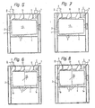
- Figure 4 shows a similar vertical section as Figure 3, but for another embodiment of the cleaning machine.
- Figure 5-8 Variants of the cleaning machines of Figures 1-4.
Die in den Fig. 1-3 dargestellte Reinigungsmaschine besitzt eine Auflösewalze 13 mit einem Walzenkörper 1, der in einem Gehäuse 2 um eine horizontale Achse drehbar gelagert ist. Der Walzenkörper 1 trägt Schlagstifte 3, die von der Umfangsfläche 4 des Walzenkörpers 1 abstehen. Die Auflösewalze 13 wird im Betrieb von einem nicht dargestellten Antriebsmotor in Pfeilrichtung gemäss Figur 1 gedreht. Unter der Unterseite der Auflösewalze 13 sind zwei nur in Figur 1 dargestellte Stabroste 5 und 6 angeordnet. Über der Oberseite der Auflösewalze 13 besitzt das Gehäuse 2 bei einem ersten Ende der Walze, rechts in Figur 1 und 3 bzw. unten in Figur 2, einen Lufteinlass 7 und bei einem zweiten Ende der Walze, links in Figur 1 und 3 bzw. oben in Figur 2, einen Luftauslass 8. In Figur 2 sind die Lagen des Einlasses 7 und des Auslasses 8 und in Figur 3 und 4 die Lagen des Auslasses 8, die hier nicht sichtbar sind, je mit einer unterbrochenen Linie angedeutet. Zwischen dem Einlass 7 und dem Auslass 8 sind über der Oberseite der Auflösewalze 13 drei zur Achse der Walze schräg gestellte Leitbleche 9,10 und 11 angeordnet, welche zwei Überleitkammern zwischen der Oberseite der Walze 13 und der oberen Wand des Gehäuses 2 begrenzen.The cleaning machine shown in FIGS. 1-3 has an
Im Betrieb werden der Reinigungsmaschine zu reinigende und aufzulösende Textilfaserflocken in einem Förderluftstrom durch den Einlass 7 zugeführt. Die Förderluft mit den Faserflocken strömt im wesentlichen zunächst um die Unterseite der drehenden Auflösewalze 13 herum, dann durch die Überleitkammer zwischen den Leitblechen 9 und 10, welche die Luft in Richtung der Achse der Auflösewalze 13 weiterbewegt, dann wieder um die Unterseite der Walze, dann durch die Überleitkammer zwischen den Leitblechen 10 und 11 und wieder um die Unterseite der Walze, um die Maschine schliesslich durch den Auslass 8 zu verlassen. Beim Herumlaufen um die Unterseite der Walze 13 werden die Faserflocken durch die Schlagstifte 3 zunehmend aufgelöst und an den Roststäben der Roste 5 und 6 streifend und schlagend vorbeigeführt, sodass Verunreinigungen von den Fasern getrennt, durch die Roste 5 und 6 hindurch abgeschieden und aus dem Raum unter den Stabrosten durch eine nicht dargestellte Absaugeinrichtung abgesaugt werden.In operation, the textile machine flakes to be cleaned and dissolved are fed in a conveying air flow through the
Die beschriebene Wirkung ist in der erfindungsgemässen Reinigungsmaschine dadurch verbessert, dass der Durchmesser des Walzenkörpers 1 vom Einlass 7 zum Auslass 8 zunimmt. Dabei können gemäss Figuren 2-4 die von der Umfangsfläche 4 des Walzenkörpers 1 aus gemessene radiale Länge der Schlagstifte 3, wie dargestellt vom ersten zum zweiten Ende der Auflösewalze, d.h. vom Einlass 7 zum Auslass 8, abnehmen. Beispielsweise kann die radiale Länge der Schlagstifte 3 beim Auslass 8 noch 25-75%, vorzugsweise etwa 50%, der radialen Länge der Schlagstifte 3 beim Einlass betragen. Dabei ist nicht auszuschliessen, dass beispielsweise auch einige der Schlagstifte 3 beim Einlass eine reduzierte Länge haben.The effect described is improved in the cleaning machine according to the invention in that the diameter of the
Die freien Enden der Schlagstifte 3 können mindestens annähernd in einer zum Walzenkörper 1 koaxialen Kreiszylinderfläche liegen. Das heisst, die freien Enden der Schlagstifte 3 haben im wesentlichen alle den gleichen Abstand von der Achse des Walzenkörpers 1 (wobei nicht auszuschliessen ist, dass einige der Schlagstifte 3 kürzer sein könnten, sodass ihre freien Enden einen kleineren Abstand von der Achse des Walzenkörpers 1 haben).The free ends of the
Der in den Figuren 1 bis 3 gezeigte Walzenkörper 1 ist konisch, so dass sein Durchmesser vom Einlass 7 zum Auslass 8 allmählich zunimmt. In gleicher Weise nimmt die radiale Länge der Schlagstifte 3 vom Einlass 7 zum Auslass 8 allmählich ab. Die Länge der Schlagstifte 3 könnte aber auch stufenweise abnehmen in der Weise, dass jeweils eine Gruppe der Schlagstifte gleiche Länge hat, eine nächste Gruppe der Schlagstifte eine etwas kleinere Länge, usw.The
Der Durchmesser des Walzenkörpers könnte vom Einlass 7 zum Auslass 8 auch stufenweise abnehmen. In Figur 4, in welcher gleiche Teile mit den gleichen Hinweisziffern wie in Figur 3 bezeichnet sind, ist eine Ausführungsform mit einem aus zwei zylindrischen Abschnitten 1a und 1b zusammengesetzten Walzenkörper dargestellt. Der beim Einlass 7, bzw. in Figur 4 rechts liegende Abschnitt 1a, hat einen kleineren Durchmesser als der in Figur 4 linke Abschnitt 1b, und die auf dem Abschnitt 1b angeordneten Schlagstifte 3 haben eine kleinere radiale Länge als die auf dem Abschnitt 1a angeordneten Schlagstifte 3, wieder derart, dass die freien Enden im wesentlichen aller Schlagstifte 3 mindestens annähernd in einer zum Walzenkörper 1a, 1b koaxialen Kreiszylinderfläche liegen. In einer Abwandlung könnten die Abschnitte 1a und/oder 1b zusätzlich leicht konisch sein. Auch könnte der Walzenkörper aus mehr als zwei Abschnitten mit vom Einlass zum Auslass zunehmenden Durchmessern zusammengesetzt sein.The diameter of the roller body could also gradually decrease from the
Die mit dem Förderluftstrom durch den Einlass 7 zugeführten Faserflocken werden in den beschriebenen Reinigungsmaschinen wie erwähnt auf dem Weg zum Auslass 8 zunehmend aufgelöst. Die Schlagstifte 3 sind durch ihre vom Einlass 7 zum Auslass 8 kleiner werdende Länge an den zunehmenden Auflösegrad angepasst. Zusätzlich kann vorteilhaft mit dem zunehmenden Auflösegrad der Faserflocken die Dichte der Schlagstifte erhöht werden, das heisst, die axialen Abstände zwischen benachbarten Schlagstiften 3 können wie dargestellt beim Auslass 8 kleiner sein als beim Einlass 7, z.B. etwa im Verhältnis 2:3. Gleichzeitig kann die in Richtung der Achse des Walzenkörpers 1 bzw. 1a, lb gemessene Dicke der Schlagstifte 3 vom Einlass 7 zum Auslass 8 abnehmen, so dass die Schlagstifte 3 beim Auslass 8 dünner sind als beim Einlass 7, z.B. ebenfalls im Verhältnis von etwa 2:3. Diese Dicke ist bei runden Schlagstiften 3 gleich dem Durchmesser derselben; die Schlagstifte 3 können aber auch andere Querschnittsformen haben, z.B. quadratisch, rechteckig usw. Anstelle der Schlagstifte können auch andere Schlagelemente verwendet werden, z.B. plättchenförmige Elemente aus Blech.The fiber flakes supplied with the conveying air flow through the
In einem praktischen Ausführungsbeispiel kann die Auflösewalze 13 die folgenden Abmessungen haben:
Länge des Walzenkörpers 1 etwa 1,6 m, Durchmesser des Walzenkörpers 1 beim Einlass 7 etwa 65 cm, beim Auslass 8 etwa 70 cm, radiale Länge der Schlagstifte 3 beim Einlass 7 etwa 5 cm, beim Auslass 8 etwa 2,5 cm, Durchmesser der Schlagstifte 3 etwa 1 cm (evtl. vom Einlass 7 zum Auslass 8 abnehmend von 1,2 auf 0,8 cm) axialer Abstand zwischen benachbarten Schlagstiften etwa 2,5 cm (evtl. vom Einlass 7 zum Auslass 8 abnehmend von 3 auf 2 cm).In a practical exemplary embodiment, the
Length of the
Die mit den Figuren 5 und 6 gezeigten Varianten betreffen die Länge der Schlagstifte 3, indem in diesen beiden Varianten die Schlagstifte über die ganze Länge des Walzenkörpers 1 dieselbe Länge aufweisen, beispielsweise 3,5 cm. Dadurch wird die auflösende Wirkung auf die genannten Ballungen von Faserflocken am Anfang des Bearbeitungsprozesses etwas reduziert, d.h. sie wird etwas weniger aggressiv als in den Ausführungsformen gemäss den Figuren 2-4. Dies ist im wesentlichen dann erwünscht, wenn Baumwolle mit eher längeren Fasern verarbeitet wird, um beim Auflösen der genannten Ballungen die Gefahr möglichst zu ver meiden, Nissen zu bilden, wobei unter Nissen kleine Verknotungen von Fasern verstanden werden.The variants shown with FIGS. 5 and 6 relate to the length of the
Eine noch konsequentere Reduktion der Aggressivität der Schlagstifte 3 am Anfang des Prozesses ist mit den Figuren 7 und 8 gezeigt, indem die Länge der Schlagstifte 3 vom Anfang des Verarbeitungsprozesses bis zum Ende zunehmen.FIGS. 7 and 8 show an even more consequent reduction in the aggressiveness of the
Diese Zunahme kann beispielsweise 25% - 100% sein. Bei einer Zunahme von 100% können die Schlagstifte am Anfang des Verarbeitungsverfahrens, beispielsweise 2,5 cm und am Ende des Verfahrens 5 cm, betragen.This increase can be, for example, 25% - 100%. With an increase of 100%, the striking pins can be 2.5 cm at the beginning of the processing process and 5 cm at the end of the process.
Mit Hilfe der zunehmenden Schlagstiftenlänge kann erreicht werden, dass, nachdem die Ballungen aufgelöst wurden, die Faserflocken mit den längeren Fasern intensiver bearbeitet werden können, als mit kürzeren Schlagstiften am Ende des Verfahrens.With the help of the increasing length of the striker it can be achieved that after the agglomerations have been dissolved, the fiber flakes with the longer fibers can be processed more intensively than with shorter striker at the end of the process.
Dabei können für die Varianten der Figuren 5 und 6 sowie 7 und 8 die bereits erwähnten Veränderungen der Dicke oder Arten der Schlagstifte zur Anwendung gelangen. Das Gleiche gilt für die ebenfalls genannte veränderbare Dichte der Schlagstifte 3 auf dem Walzenkörper 1.The changes in the thickness or types of striker pins already mentioned can be used for the variants of FIGS. 5 and 6 and 7 and 8. The same applies to the also mentioned changeable density of the
Claims (11)
dadurch gekennzeichnet, dass der Durchmesser des Walzenkörpers (1; 1a, 1b) vom ersten zum zweiten Ende der Auflösewalze (1, 3; 1a, 1b, 3) zunimmt.1. Cleaning machine for textile fibers transported in a conveying air stream, with a horizontal opening roller, which has a roller body (1; 1a, 1b) and impact elements (3) projecting from the peripheral surface (4) of the roller body, with under the underside of the opening roller (1, 3; 1a, 1b, 3) arranged bar grids (5, 6) and with an inlet (7) and an outlet (8) for the conveying air flow, which at a first and a second end of the opening roller (1, 3; 1a , 1b, 3) are arranged,
characterized in that the diameter of the roller body (1; 1a, 1b) increases from the first to the second end of the opening roller (1, 3; 1a, 1b, 3).
dadurch gekennzeichnet, dass der Walzenkörper (1) konisch ist.2. Cleaning machine according to claim 1,
characterized in that the roller body (1) is conical.
dadurch gekennzeichnet, dass der Walzenkörper stufenweise zunimmt.3. Cleaning machine according to claim 1,
characterized in that the roller body increases gradually.
dadurch gekennzeichnet, dass die Länge der Schlagelemente (3) von der Umfangsfläche (4) des Walzenkörpers (1; 1a, 1b) aus gemessen, vom ersten zum zweiten Ende der Auflösewalze (1, 3; 1a, 1b, 3) abnimmt.4. Cleaning machine according to claim 1 or 2,
characterized in that the length of the striking elements (3) measured from the peripheral surface (4) of the roller body (1; 1a, 1b) decreases from the first to the second end of the opening roller (1, 3; 1a, 1b, 3).
dadurch gekennzeichnet, dass die Länge der Schlagelemente (3) beim zweiten Ende der Auflösewalze (1, 3; 1a, 1b, 3) 25 bis 75%, vorzugsweise etwa 50%, der Länge der Schlagelemente beim ersten Ende der Auflösewalze (1, 3; 1a, 1b, 3) beträgt.5. Cleaning machine according to claim 4,
characterized in that the length of the striking elements (3) at the second end of the opening roller (1, 3; 1a, 1b, 3) 25 to 75%, preferably about 50%, of the length of the striking elements at the first end of the opening roller (1, 3 ; 1a, 1b, 3).
dadurch gekennzeichnet, dass die freien Enden der Schlagelemente (3) mindestens annähernd in einer zum Walzenkörper (1; 1a, 1b) koaxialen Kreiszylinderfläche liegen.6. Cleaning machine according to claim 4 or 5,
characterized in that the free ends of the striking elements (3) lie at least approximately in a circular cylindrical surface coaxial with the roller body (1; 1a, 1b).
dadurch gekennzeichnet, dass die Länge der Schlagelemente (3) von der Umfangsfläche (4) des Walzenkörpers (1; 1a, 1b) aus gemessen, vom ersten zum zweiten Ende der Auflösewalze (4) im wesentlichen gleich bleibt.7. Cleaning machine according to claim 1,
characterized in that the length of the striking elements (3) measured from the peripheral surface (4) of the roller body (1; 1a, 1b) remains essentially the same from the first to the second end of the opening roller (4).
dadurch gekennzeichnet, dass die Länge der Schlagelemente (3) von der Umfangsfläche (4) des Walzenkörpers (1; 1a, 1b) aus gemessen in einem vorgegebenen Masse zunimmt.8. Cleaning machine according to claim 1,
characterized in that the length of the striking elements (3) increases from the circumferential surface (4) of the roller body (1; 1a, 1b) to a predetermined extent.
dadurch gekennzeichnet, dass die Länge der Schlagelemente (3) von der Umfangsfläche (4) des Walzenkörpers (1; 1a, 1b) aus gemessen von 25% bis 100% zunimmt.9. Cleaning machine according to claim 8,
characterized in that the length of the striking elements (3) increases from 25% to 100% as measured from the peripheral surface (4) of the roller body (1; 1a, 1b).
dadurch gekennzeichnet, dass der axiale Abstand zwischen benachbarten Schlagelementen (3) vom ersten zum zweiten Ende der Auflösewalze (1, 3; 1a, 1b, 3) abnimmt.10. Cleaning machine according to one of claims 1-9,
characterized in that the axial distance between adjacent impact elements (3) from decreases first to the second end of the opening roller (1, 3; 1a, 1b, 3).
dadurch gekennzeichnet, dass die axiale Dicke der Schlagelemente (3) vom ersten zum zweiten Ende der Auflösewalze (1, 3; 1a, 1b, 3) abnimmt.11. Cleaning machine according to one of claims 1 to 10,
characterized in that the axial thickness of the striking elements (3) decreases from the first to the second end of the opening roller (1, 3; 1a, 1b, 3).
Applications Claiming Priority (2)
| Application Number | Priority Date | Filing Date | Title |
|---|---|---|---|
| CH320/89 | 1989-01-31 | ||
| CH32089 | 1989-01-31 |
Publications (1)
| Publication Number | Publication Date |
|---|---|
| EP0380936A1 true EP0380936A1 (en) | 1990-08-08 |
Family
ID=4184336
Family Applications (1)
| Application Number | Title | Priority Date | Filing Date |
|---|---|---|---|
| EP90100481A Ceased EP0380936A1 (en) | 1989-01-31 | 1990-01-11 | Cleaning machine for textile fibres |
Country Status (3)
| Country | Link |
|---|---|
| US (1) | US5018247A (en) |
| EP (1) | EP0380936A1 (en) |
| JP (1) | JPH02289123A (en) |
Cited By (4)
| Publication number | Priority date | Publication date | Assignee | Title |
|---|---|---|---|---|
| EP0464441A1 (en) * | 1990-07-02 | 1992-01-08 | Maschinenfabrik Rieter Ag | Method and apparatus for cleaning cotton fibres |
| US5237727A (en) * | 1990-07-02 | 1993-08-24 | Maschinenfabrik Rieter Ag | Adjustable cleaning of fibers in a spiralled air path and apparatus |
| WO2000029649A1 (en) * | 1998-11-16 | 2000-05-25 | Pragmatic Vision, Inc. | Disperser |
| CN103993392A (en) * | 2014-05-26 | 2014-08-20 | 江苏双盈纺织科技有限公司 | Efficient opener |
Families Citing this family (2)
| Publication number | Priority date | Publication date | Assignee | Title |
|---|---|---|---|---|
| CN101812745B (en) * | 2010-04-27 | 2011-07-20 | 恒天重工股份有限公司 | Opening and cleaning method for axial flow opener for opening picking or blowing carding process and special composite beater device thereof |
| CH713995A2 (en) * | 2017-07-17 | 2019-01-31 | Rieter Ag Maschf | Cleaning device. |
Citations (4)
| Publication number | Priority date | Publication date | Assignee | Title |
|---|---|---|---|---|
| GB162667A (en) * | 1920-05-03 | 1922-11-02 | Miguel Carcabilla | Improved machine for softening and cleaning wool, cotton, flock, hair, straw and the like by beating |
| US1459938A (en) * | 1922-07-20 | 1923-06-26 | Davis & Furber | Cone duster |
| DE508356C (en) * | 1930-09-27 | August Aeldert | Machine for cleaning waste paper, rags and similar goods | |
| GB1009284A (en) * | 1964-02-19 | 1965-11-10 | Isolier Und Kaltetechnik Rosto | Opening and feeding device for fibre materials, such as asbestos, slag wool or the like |
Family Cites Families (5)
| Publication number | Priority date | Publication date | Assignee | Title |
|---|---|---|---|---|
| DE250077C (en) * | ||||
| US788812A (en) * | 1904-05-28 | 1905-05-02 | Dixie Cotton Picker Company | Cotton-picking machine. |
| US2411575A (en) * | 1944-11-28 | 1946-11-26 | Arthur J Kay | Cotton picker |
| US3968542A (en) * | 1975-03-21 | 1976-07-13 | Hollingsworth John D | Beater roll |
| DE3333750A1 (en) * | 1983-09-19 | 1985-04-18 | Trützschler GmbH & Co KG, 4050 Mönchengladbach | DEVICE AND METHOD FOR OPENING AND CLEANING FIBER GOODS |
-
1990
- 1990-01-11 EP EP90100481A patent/EP0380936A1/en not_active Ceased
- 1990-01-31 JP JP2019383A patent/JPH02289123A/en active Pending
- 1990-01-31 US US07/472,796 patent/US5018247A/en not_active Expired - Fee Related
Patent Citations (4)
| Publication number | Priority date | Publication date | Assignee | Title |
|---|---|---|---|---|
| DE508356C (en) * | 1930-09-27 | August Aeldert | Machine for cleaning waste paper, rags and similar goods | |
| GB162667A (en) * | 1920-05-03 | 1922-11-02 | Miguel Carcabilla | Improved machine for softening and cleaning wool, cotton, flock, hair, straw and the like by beating |
| US1459938A (en) * | 1922-07-20 | 1923-06-26 | Davis & Furber | Cone duster |
| GB1009284A (en) * | 1964-02-19 | 1965-11-10 | Isolier Und Kaltetechnik Rosto | Opening and feeding device for fibre materials, such as asbestos, slag wool or the like |
Cited By (5)
| Publication number | Priority date | Publication date | Assignee | Title |
|---|---|---|---|---|
| EP0464441A1 (en) * | 1990-07-02 | 1992-01-08 | Maschinenfabrik Rieter Ag | Method and apparatus for cleaning cotton fibres |
| US5237727A (en) * | 1990-07-02 | 1993-08-24 | Maschinenfabrik Rieter Ag | Adjustable cleaning of fibers in a spiralled air path and apparatus |
| WO2000029649A1 (en) * | 1998-11-16 | 2000-05-25 | Pragmatic Vision, Inc. | Disperser |
| CN103993392A (en) * | 2014-05-26 | 2014-08-20 | 江苏双盈纺织科技有限公司 | Efficient opener |
| CN103993392B (en) * | 2014-05-26 | 2016-02-10 | 江苏双盈纺织科技有限公司 | A kind of high-efficiency opener |
Also Published As
| Publication number | Publication date |
|---|---|
| US5018247A (en) | 1991-05-28 |
| JPH02289123A (en) | 1990-11-29 |
Similar Documents
| Publication | Publication Date | Title |
|---|---|---|
| AT390812B (en) | WASHING DEVICE FOR FIBER FIBER SUSPENSIONS | |
| EP0494181B1 (en) | Process and device for opening and cleaning fibre material | |
| CH622033A5 (en) | ||
| CH626660A5 (en) | ||
| EP1657328B1 (en) | Fibre-opening unit having teeth with improved contour | |
| DE2648715A1 (en) | METHOD AND DEVICE FOR CLEANING FIBER MATERIAL | |
| DE3711640C2 (en) | ||
| DE1091011B (en) | Device for opening, cleaning and mixing fiber material | |
| CH674744A5 (en) | ||
| DE69121314T2 (en) | Method and device for opening and cleaning fiber material in an opener | |
| EP0380936A1 (en) | Cleaning machine for textile fibres | |
| DE68901813T2 (en) | PAPER MAKING MACHINE. | |
| EP0381860B1 (en) | Cleaning machine for textile fibres | |
| EP0586641A1 (en) | Dirt-separating intake | |
| EP0455017B1 (en) | Opening roller for spinning machines | |
| EP1866468B1 (en) | Grate bar | |
| DE2909133C2 (en) | ||
| EP0419416A1 (en) | Apparatus for fine cleaning of textile fibres | |
| EP0931584A1 (en) | Apparatus for the mechanical handling of high consistency fibrous material | |
| EP0186738B1 (en) | Sorting apparatus for fibre suspensions | |
| EP0381186A2 (en) | Opening apparatus | |
| EP1229157A1 (en) | Processing machine for textile fibre flocks | |
| DE2515780A1 (en) | Opener and cleaner for fibres to be spun - esp cotton, etc. for rotor spinning, removing all dust | |
| DE1899360U (en) | DRAWER FOR SPINNING MACHINES. | |
| CH519031A (en) | Removal of carding fly - by suction devices fitted to a carding machine |
Legal Events
| Date | Code | Title | Description |
|---|---|---|---|
| PUAI | Public reference made under article 153(3) epc to a published international application that has entered the european phase |
Free format text: ORIGINAL CODE: 0009012 |
|
| AK | Designated contracting states |
Kind code of ref document: A1 Designated state(s): CH DE FR GB IT LI |
|
| 17P | Request for examination filed |
Effective date: 19900904 |
|
| 17Q | First examination report despatched |
Effective date: 19920226 |
|
| STAA | Information on the status of an ep patent application or granted ep patent |
Free format text: STATUS: THE APPLICATION HAS BEEN REFUSED |
|
| 18R | Application refused |
Effective date: 19950108 |