EP0377136B1 - Adaptives Datenübertragungsprotokoll - Google Patents
Adaptives Datenübertragungsprotokoll Download PDFInfo
- Publication number
- EP0377136B1 EP0377136B1 EP89122802A EP89122802A EP0377136B1 EP 0377136 B1 EP0377136 B1 EP 0377136B1 EP 89122802 A EP89122802 A EP 89122802A EP 89122802 A EP89122802 A EP 89122802A EP 0377136 B1 EP0377136 B1 EP 0377136B1
- Authority
- EP
- European Patent Office
- Prior art keywords
- data
- terminal
- packet
- packets
- window
- Prior art date
- Legal status (The legal status is an assumption and is not a legal conclusion. Google has not performed a legal analysis and makes no representation as to the accuracy of the status listed.)
- Expired - Lifetime
Links
- 230000003044 adaptive effect Effects 0.000 title description 4
- 230000015654 memory Effects 0.000 claims description 107
- 230000005540 biological transmission Effects 0.000 claims description 105
- 238000000034 method Methods 0.000 claims description 35
- 230000004044 response Effects 0.000 claims description 13
- 238000001514 detection method Methods 0.000 claims description 8
- 238000004891 communication Methods 0.000 description 27
- 238000011084 recovery Methods 0.000 description 14
- 238000010276 construction Methods 0.000 description 12
- 230000006870 function Effects 0.000 description 11
- 238000012937 correction Methods 0.000 description 7
- 239000013307 optical fiber Substances 0.000 description 6
- 238000010586 diagram Methods 0.000 description 5
- 230000003466 anti-cipated effect Effects 0.000 description 4
- 125000004122 cyclic group Chemical group 0.000 description 4
- 239000000835 fiber Substances 0.000 description 4
- 230000007246 mechanism Effects 0.000 description 4
- 230000003287 optical effect Effects 0.000 description 4
- 238000012545 processing Methods 0.000 description 4
- 230000008901 benefit Effects 0.000 description 3
- 230000008569 process Effects 0.000 description 3
- 238000009432 framing Methods 0.000 description 2
- 230000002441 reversible effect Effects 0.000 description 2
- 230000008859 change Effects 0.000 description 1
- 238000013500 data storage Methods 0.000 description 1
- 230000002950 deficient Effects 0.000 description 1
- 230000003111 delayed effect Effects 0.000 description 1
- 230000001419 dependent effect Effects 0.000 description 1
- 238000013461 design Methods 0.000 description 1
- 238000000605 extraction Methods 0.000 description 1
- 230000000977 initiatory effect Effects 0.000 description 1
- 230000014759 maintenance of location Effects 0.000 description 1
- 238000007726 management method Methods 0.000 description 1
- 238000005259 measurement Methods 0.000 description 1
- 238000012986 modification Methods 0.000 description 1
- 230000004048 modification Effects 0.000 description 1
- 230000008520 organization Effects 0.000 description 1
- 230000002035 prolonged effect Effects 0.000 description 1
- 230000000246 remedial effect Effects 0.000 description 1
- 230000000717 retained effect Effects 0.000 description 1
- 238000012552 review Methods 0.000 description 1
- 238000012163 sequencing technique Methods 0.000 description 1
- 230000002459 sustained effect Effects 0.000 description 1
- 230000001360 synchronised effect Effects 0.000 description 1
- 239000002699 waste material Substances 0.000 description 1
Images


Classifications
-
- H—ELECTRICITY
- H04—ELECTRIC COMMUNICATION TECHNIQUE
- H04L—TRANSMISSION OF DIGITAL INFORMATION, e.g. TELEGRAPHIC COMMUNICATION
- H04L1/00—Arrangements for detecting or preventing errors in the information received
- H04L1/12—Arrangements for detecting or preventing errors in the information received by using return channel
- H04L1/16—Arrangements for detecting or preventing errors in the information received by using return channel in which the return channel carries supervisory signals, e.g. repetition request signals
- H04L1/18—Automatic repetition systems, e.g. Van Duuren systems
- H04L1/1825—Adaptation of specific ARQ protocol parameters according to transmission conditions
-
- H—ELECTRICITY
- H04—ELECTRIC COMMUNICATION TECHNIQUE
- H04L—TRANSMISSION OF DIGITAL INFORMATION, e.g. TELEGRAPHIC COMMUNICATION
- H04L1/00—Arrangements for detecting or preventing errors in the information received
- H04L1/0001—Systems modifying transmission characteristics according to link quality, e.g. power backoff
- H04L1/0006—Systems modifying transmission characteristics according to link quality, e.g. power backoff by adapting the transmission format
- H04L1/0007—Systems modifying transmission characteristics according to link quality, e.g. power backoff by adapting the transmission format by modifying the frame length
-
- H—ELECTRICITY
- H04—ELECTRIC COMMUNICATION TECHNIQUE
- H04L—TRANSMISSION OF DIGITAL INFORMATION, e.g. TELEGRAPHIC COMMUNICATION
- H04L1/00—Arrangements for detecting or preventing errors in the information received
- H04L1/12—Arrangements for detecting or preventing errors in the information received by using return channel
- H04L1/16—Arrangements for detecting or preventing errors in the information received by using return channel in which the return channel carries supervisory signals, e.g. repetition request signals
- H04L1/1607—Details of the supervisory signal
- H04L1/1671—Details of the supervisory signal the supervisory signal being transmitted together with control information
-
- H—ELECTRICITY
- H04—ELECTRIC COMMUNICATION TECHNIQUE
- H04L—TRANSMISSION OF DIGITAL INFORMATION, e.g. TELEGRAPHIC COMMUNICATION
- H04L1/00—Arrangements for detecting or preventing errors in the information received
- H04L1/12—Arrangements for detecting or preventing errors in the information received by using return channel
- H04L1/16—Arrangements for detecting or preventing errors in the information received by using return channel in which the return channel carries supervisory signals, e.g. repetition request signals
- H04L1/1607—Details of the supervisory signal
- H04L1/1685—Details of the supervisory signal the supervisory signal being transmitted in response to a specific request, e.g. to a polling signal
-
- H—ELECTRICITY
- H04—ELECTRIC COMMUNICATION TECHNIQUE
- H04L—TRANSMISSION OF DIGITAL INFORMATION, e.g. TELEGRAPHIC COMMUNICATION
- H04L1/00—Arrangements for detecting or preventing errors in the information received
- H04L1/12—Arrangements for detecting or preventing errors in the information received by using return channel
- H04L1/16—Arrangements for detecting or preventing errors in the information received by using return channel in which the return channel carries supervisory signals, e.g. repetition request signals
- H04L1/18—Automatic repetition systems, e.g. Van Duuren systems
- H04L1/1806—Go-back-N protocols
-
- H—ELECTRICITY
- H04—ELECTRIC COMMUNICATION TECHNIQUE
- H04L—TRANSMISSION OF DIGITAL INFORMATION, e.g. TELEGRAPHIC COMMUNICATION
- H04L1/00—Arrangements for detecting or preventing errors in the information received
- H04L1/12—Arrangements for detecting or preventing errors in the information received by using return channel
- H04L1/16—Arrangements for detecting or preventing errors in the information received by using return channel in which the return channel carries supervisory signals, e.g. repetition request signals
- H04L1/18—Automatic repetition systems, e.g. Van Duuren systems
- H04L1/1829—Arrangements specially adapted for the receiver end
- H04L1/1832—Details of sliding window management
-
- H—ELECTRICITY
- H04—ELECTRIC COMMUNICATION TECHNIQUE
- H04L—TRANSMISSION OF DIGITAL INFORMATION, e.g. TELEGRAPHIC COMMUNICATION
- H04L1/00—Arrangements for detecting or preventing errors in the information received
- H04L1/12—Arrangements for detecting or preventing errors in the information received by using return channel
- H04L1/16—Arrangements for detecting or preventing errors in the information received by using return channel in which the return channel carries supervisory signals, e.g. repetition request signals
- H04L1/18—Automatic repetition systems, e.g. Van Duuren systems
- H04L1/1867—Arrangements specially adapted for the transmitter end
- H04L1/187—Details of sliding window management
-
- H—ELECTRICITY
- H04—ELECTRIC COMMUNICATION TECHNIQUE
- H04L—TRANSMISSION OF DIGITAL INFORMATION, e.g. TELEGRAPHIC COMMUNICATION
- H04L1/00—Arrangements for detecting or preventing errors in the information received
- H04L1/12—Arrangements for detecting or preventing errors in the information received by using return channel
- H04L1/16—Arrangements for detecting or preventing errors in the information received by using return channel in which the return channel carries supervisory signals, e.g. repetition request signals
- H04L1/18—Automatic repetition systems, e.g. Van Duuren systems
- H04L1/1829—Arrangements specially adapted for the receiver end
- H04L1/1835—Buffer management
-
- H—ELECTRICITY
- H04—ELECTRIC COMMUNICATION TECHNIQUE
- H04L—TRANSMISSION OF DIGITAL INFORMATION, e.g. TELEGRAPHIC COMMUNICATION
- H04L1/00—Arrangements for detecting or preventing errors in the information received
- H04L1/12—Arrangements for detecting or preventing errors in the information received by using return channel
- H04L1/16—Arrangements for detecting or preventing errors in the information received by using return channel in which the return channel carries supervisory signals, e.g. repetition request signals
- H04L1/18—Automatic repetition systems, e.g. Van Duuren systems
- H04L1/1867—Arrangements specially adapted for the transmitter end
- H04L1/188—Time-out mechanisms
-
- H—ELECTRICITY
- H04—ELECTRIC COMMUNICATION TECHNIQUE
- H04L—TRANSMISSION OF DIGITAL INFORMATION, e.g. TELEGRAPHIC COMMUNICATION
- H04L1/00—Arrangements for detecting or preventing errors in the information received
- H04L2001/0092—Error control systems characterised by the topology of the transmission link
- H04L2001/0094—Bus
Definitions
- This invention relates to architecture for a data link control protocol suitable for a duplex digital data transmission system employing error recovery based on a GO-BACK-N algorithm for retransmission of data frames of a window subsequent to the detection of an error and, more particularly, to the construction of such an architecture with a digital word format permitting parallel processing of individual bits of a word to allow for error detection and recovery at rates commensurate with the high data-transmission rates of pulsed optical communication links.
- Digital communication systems are widely used for communicating digitized data among people who use the data.
- data may include pictorial information sent by facsimile, textual data for publishing purposes, and numeric data as may be employed by computer companies, the latter two forms of data being transmitted frequently by the use of modems connected to a telephone line or high-speed data line.
- Large amounts of data to be transmitted over a single communication link are generally multiplexed and modulated onto an electromagnetic carrier for transmission over a coaxial cable, or pulse modulated onto a light beam for transmission by fiber optics.
- the data is transmitted, typically, in the form of batches or packets along with some form of coding, such as a cyclic redundancy check (CRC), which allows for a receiver to verify that the received packet of data may be regarded as being free of error.
- CRC cyclic redundancy check
- the packet is rejected, and the receiving terminal requests the transmitting terminal of the communication link to retransmit the rejected packet.
- the capacity for transmitting the request for retransmission is provided by the duplex link wherein transmission is possible in both directions.
- a communication system for communicating digitized data among a group of computers is disclosed in an article entitled "VAXclusters: A Closely-Coupled Distributed System" by N. P. Kronenberg, H. M. Levy, and W. D. Strecker in ACM Transactions on Computer systems, Vol. 4, No. 2.
- This article discloses a star-shaped array of data buses with arbitration and acknowledgement of buses for connecting between two terminals.
- U.S. patent 4 527 267 discloses a communication system with administration of acknowledgement packets, and employs an internal protocol of a transport switching network with windows of authorized data packets to be transmitted.
- U.S. patent 4 677 614 discloses a multi-node loop form of communication system wherein any one of the nodes can assume the role of a master node to provide a time base for the loop.
- a communication link provides two-way communication between two terminals at the ends of the link.
- Data is transmitted along the link in the form of data packets, wherein each packet also includes control words and status bits which identify each packet by a sequence, and carry messages such as a request for an acknowledgement of successful transmission, and to indicate a retransmission of a packet when such retransmission has been requested because of a communication error.
- Synchronization is facilitated by the use of a pair of memories, one at each terminal, wherein storage compartments are arranged in the same fashion within each memory.
- the storage compartments are divided among data frames, with groups of frames being arranged as sub-windows of a window.
- the window is the complete array of frames in the memory.
- the sequence number of each packet is equal to the number of the frame in which the data is stored.
- the data in each frame is transmitted as a separate packet.
- the data Upon receipt of a valid packet, the data is stored in the corresponding frame of the received memory. All packets are checked for error before being stored in the received memory.
- the omission of the packet is readily determined by comparison of sequence numbers of received packets with an incoming packet.
- This arrangement is readily implemented by use of programmable array logic (PAL) units in the construction of state machines which can operate faster than a general purpose microprocessor in carrying out the synchronization function.
- PAL programmable array logic
- a request for an acknowledgement signal is included within the packet at the end of each sub-window.
- transmission of subsequent frames need not be delayed until an acknowledgement signal has been received. Rather, the transmission of subsequent frames is allowed to continue for a predetermined amount of time, whether or not the acknowledgement signal has been received.
- acknowledgement signal When an acknowledgement signal is received, status bits are changed from "awaiting acknowledgement” to "acknowledgement received", the status bits being appended to the corresponding data packet in the transmit memory.
- the data of all frames is retained in storage in the main memory until the complete window has been sent. The retention of the data permits retransmission of data packets in the event that a faulty transmission has occurred.
- a PAL unit can readily review the status of the frames to determine whether an acknowledgement (Ack) signal has been received.
- the invention provides for an error recovery mechanism implemented by the data link control.
- the receiving terminal Upon detection of an error in data or a sequence error by the receiving terminal, the receiving terminal transmits a message to the transmit terminal indicating that there has been a faulty transmission and, further indicating the sequence number of the data frame for which the fault occurred.
- the transmit terminal goes back to the sub-window and frame specified in the error message, and resumes transmission with the sub-window and frame specified in the error message.
- a status bit is set to indicate that this a retransmission.
- the receiving terminal upon seeing the message with the indication of retransmission, and upon properly receiving this packet, sends the Ack message with the status bit indicating that the acknowledgement is in response to the retransmitted data packet. This informs the data transmit terminal that the GO-BACK procedure has been completed.
- Timing of the recovery interval begins upon reception of the error message, and is terminated upon receipt of the status bit indicating that the GO-BACK procedure has been completed.
- the timer is also operated in the event that a status of Awaiting Acknowledgement is found in the status bits of each data frame stored in the transmit memory.
- the transmit terminal inserts the message "I Need Status" within the data packet and starts the timer.
- the timer is reset when the "Awaiting Ack" is alleviated by receipt of an Ack signal or upon completion of a data recovery procedure. Should the elapsed time exceed an allowable amount, a warning indicator is activated to alert personnel at the transmit terminal.
- the use of the status bits in cooperation with the timer provide for greater efficiency during the link re-synchronization cycle after a packet error.
- the system architecture operates independently of the data packet size because all of the control words and status bits are set in a portion of the data packet separate from the data itself, and separate from a cyclic redundancy check (CRC) code which is employed in checking for error in transmission. Therefore, the data portion of a transmitted packet may be small, large, or varied in length in accordance with the adaptive capability of the system. Variation of the number of frames between a request for acknowledgement, as well as variation in the length of the data portion of each packet permits the acknowledgement signals be sent more or less frequently depending on the system response to error rate, packet or bit error rate, along the communication link. For high quality transmission links, the error rate is so low that it is highly unlikely that more than one bit per packet would be in error. Therefore, as a practical matter in the implementation of the system, the bit error rate and the packet error rate may be regarded as being the same.
- Fig. 1 shows a two-way (duplex) data transmission system 20 allowing two users 22 and 24 to communicate with each other.
- the system 20 comprises two terminals 26 and 28 coupled by a full duplex data transmission link 30.
- the link 30, may be constructed of two optical fibers wherein one optical fiber provides simplex transmission of data and control signals from the terminal 26 to the terminal 28, and the second optical fiber providing simplex transmission of data and control signals from the terminal 28 to the terminal 26.
- the transmission link 30 may be constructed of a coaxial cable or a telephone transmission line to provide for the duplex transmission; however, full advantage of the invention can only be attained with the high-speed transmission of an optical link.
- the terminal 26 connects with the user 22, and the terminal 28 connects with the user 24.
- the two terminals 26 and 28 are constructed of the same components, and are operated to provide their respective functions of transmission and reception.
- the terminal 26 comprises a memory 32, a transmitter 34, a receiver 36, a control logic unit 38, and an interface 40.
- the terminal 28 comprises a memory 42, a transmitter 44, a receiver 46, a control logic unit 48, and an interface 50.
- the control logic unit 38 connects with the memory 32, the transmitter 34, and the receiver 36 for the application of control signals to operate these units.
- the control logic unit 48 connects with the memory 42, the transmitter 44 and the receiver 46 for applying control signals to operate these units.
- the interfaces 40 and 50 operate to couple signals between the link 30 and the transmitters 34, 44, and the receivers 36, 46.
- Operation of the system 20 may be demonstrated by the transmission of data from the user 22 to the user 24.
- the data is first stored in the memory 32 so as to become available to the transmitter 34 for transmission to the terminal 28.
- the data from the user 22 is entered into the memory 32 by arranging the data in the memory 32 as a set of frames which, together, form a window of data.
- the window is divided into sub-windows to facilitate data transmission, as will be described hereinafter.
- the window is outputted to the transmitter 34 under control of the logic unit 38 for transmission via the link 30.
- each frame is transmitted as a separate data packet comprising data and control words, as well as an error correction code, a message type, and flags designating the start and end of a packet, as will be described hereinafter in further detail.
- BER bit error rate
- each frame is transmitted as a separate data packet comprising data and control words, as well as an error correction code, a message type, and flags designating the start and end of a packet, as will be described hereinafter in further detail.
- the length of a frame and the corresponding length of the data portion of a packet may be reduced.
- the transmission of a sub-window is preceded by a header identifying the number of frames in the sub-window.
- control signals embedded in the control words and the message type of each packet identify each frame of the sub-window to enable the receiving terminal 28 to compare the anticipated sequence of frame arrivals with the sequence of frames as actually received.
- the data frames are received by the receiver 46, the receiver 46 also providing an error check of each data word by a cyclic redundancy check (CRC) to verify that data in each frame head is valid.
- CRC cyclic redundancy check
- the result of such invalid data is to alter the sequence of stored frames in the memory 42 from that which has been expected.
- the transmitter 44 is activated to transmit a signal back to the transmitting terminal 26 requesting that the present sequence of frame transmission be stopped and that the transmission be restarted with the frame containing the faulty packet.
- the window of the memory 42 is filled with data which accurately matches the data originally stored in the window of the memory 32.
- the memory 32 retains storage of the data, even after transmission of the data, until such time as an acknowledgement signal has been transmitted from the receiving terminal 28 to the transmitting terminal 26 to acknowledge that all of the data has been correctly received. Thereupon, the data is dumped from the memory 32 to provide space for receiving further data from the user 22.
- the data of the memory 42 is transferred to the user 24 with a clearing of the memory 42 so as to permit entry of further data.
- the system 20 is able to transmit data accurately from the user 22 to the user 24.
- the system 20 can operate in the same fashion in the reverse direction so as to enable the transmission of data from the user 24 to the user 22.
- Fig. 2 is useful in explaining a further feature of the invention wherein control signals are embedded in each packet for controlling operation of the system 20.
- the control signals may be present in a packet irrespectively of whether or not the packet contains any data.
- a packet traveling from the terminal 26 to the terminal 28 contains both control signals and data.
- an acknowledgement signal and a signal requesting a retransmission would be transmitted in a packet which carries no data.
- the transmission of bits of each packet is conducted in serial fashion along the link 30.
- the bits of each packet are transmitted along the fiber serially.
- the bits may also be formed as a pulse modulation of an electromagnetic carrier signal in which case the bits are transmitted serially.
- Serially transmitted signals are converted into a parallel signal, by use of a shift register 52.
- the parallel output lines are applied to field-recognition circuitry 54 which identifies the various fields in each packet so as to permit rapid extraction of the control signals from the packet.
- Data and an error checking code are outputted by the recognition circuitry 54 to a data error checker 56 which operates in a well-known fashion to make the data available for entry into the memory 42, and to output a check signal on line 58 indicating whether or not the data is error free.
- the check signal on line 58 is applied to the control logic unit 48 for use in the generation of a request for retransmission of data, as will be described hereinafter.
- the parallel processing of the respective fields of a packet enables the circuitry of the receiving terminal 28 to operate at the same rate at which the data is being transmitted.
- a window of the memory 32 may be divided into smaller sub-windows each of which has a reduced number of frames so as to increase the frequency at which acknowledgement signals are received from the receiving terminal 28 back at the transmitting terminal 26.
- the increased rate of acknowledgement signals is most useful in the case of a noisy environment at the link 30 wherein higher error rates may exist. This reduces the total number of frames which may have to be retransmitted in the event of an error being detected within a sub-window.
- the changing of the sub-window size can be accomplished automatically by the system 20 by counting the number of negative-acknowledgment (NACK) signals during a predetermined interval of time. These functions are accomplished by use of the control logic units 38 and 48.
- NACK negative-acknowledgment
- PAL units 60 are available commercially and are readily connected and programmed to perform a fixed logic routine.
- the latches 62 which may be constructed as type-D flip-flops, are employed to store the bits of digital signals representing specific states of the system 20, such as a state of waiting for an acknowledgment signal, a state of an empty memory frame ready to receive new data, or a state of a loaded memory frame ready to discharge data. Additional commands, as well as a sequence of commands, may be stored in a program memory 68.
- the interconnection of the counter 66, and the memory 68 with the latches 62 and the PAL units 60, as shown in Fig. 3 represent a typical interconnection scheme, and are provided to demonstrate the use of these elements in the construction of the logic unit 38. It is understood that the total number of PAL units 60 and latches 62 is dependent upon the specific programming and logic functions to be provided by the logic unit 38 as will be discussed hereinafter. It is noted also that the logic unit 48 is constructed in the same fashion as the logic unit 38 and, accordingly, the explanation of the logic unit 38 is to be understood to apply also to the logic unit 48.
- the control logic unit 38 also includes an address generator 76, responsive to the PAL unit 60, for addressing the memory 32 to select frames, or portions of a frame into which data is to be written and from which data is to be read out.
- the system 20 is capable of providing for accurate transmission of data at substantially higher data rates than has been available heretofore.
- the novel features of the architecture and protocol which make the operation possible is explained now in further detail by reference to the specific arrangement of frames in the window, and the specific formatting of packets to provide for the embedding of control signals within a data-carrying packet.
- One mode is to repeat the transmission of a packet of data which was determined to be defective during the initial transmission.
- a second mode the serial transmission of a succession of data packets is stopped, and the transmission sequence reverts back to the packet with the faulty data for a retransmission of this packet along with all subsequent packets of the sequence which may have already have been transmitted.
- additional information is transmitted with each data packet, which information is sufficient to regenerate a portion of data which has been lost or corrupted during a transmission.
- each of these modes may be useful in particular situations depending on error rate, the rate of transmission speed, and the availability of a transmission in the reverse direction to notify a sender of a transmission failure.
- the invention is intended for use in a duplex data transmission system which allows for the transmission of messages to the sender acknowledging whether data has been accurately received or whether there has been a faulty transmission of the data. Therefore, only the first two of the foregoing data correction modes are candidates for use in the system of the invention.
- Fig. 4 shows the efficiency of data transmission, as a function of bit error rate, for the first two of the foregoing modes of data correction.
- the selective repetition of only a data packet experiencing a faulty transmission would be the ideal protocol for data link control because this mode minimizes a number of packets which must be retransmitted.
- the second of the foregoing modes namely the retransmitting of a sequence of data packets beginning with the packet experiencing the - failure can be more easily implemented in terms of the construction of the transmission system.
- Fig. 4 shows that for a relatively low BER, the two modes of correction provide essentially the same throughput efficiency. Accordingly, either of these two modes may be employed in the construction of a high-speed low-BER transmission system.
- the second mode namely the retransmission of the sequence of packets beginning with the faulty packet is employed in the construction of the system of the invention.
- Fig. 5 presents a diagram of a memory 32 showing an arrangement of frames 70 in a window 72.
- the window may be divided into sub-windows 74 for improved efficiency of data transmission in an environment of increased bit error rate.
- the frames 70 are selected by the address generator 76 (Fig. 3) in accordance with a program to be described hereinafter.
- a packet of data comprises the data of a single frame 70.
- a data packet may be configured with a smaller quantity of data, such as the data stored in one-half of a frame 70.
- Each of the sub-windows define sequences of frames of data to be transmitted from the user 22 to the user 24.
- an acknowledgement signal (Ack) is sent from the terminal 28 back to the terminal 26.
- the frames of the window are cleared to receive further data from the user 22.
- the error signal includes identification of the frame containing the data of the unsuccessful transmission. Then, in response to the error signal, the data of that frame plus the packets of data of the succeeding frames are retransmitted from the terminal 26 to the terminal 28. Thereupon, assuming that successful acknowledgement is received, the series of data transmissions proceeds with the next sub-window.
- NACK negative acknowledgement
- the series of data transmissions proceeds with the next sub-window.
- Fig. 6 shows the arrangement of frames of the transmitting memory 32 of the transmitting terminal 26, and the frames of the receiving memory 42 of the receiving terminal 28.
- Fig. 6 is useful in describing the memory architecture of the data link control.
- each of these memories provides for the storage of 512 K bytes of data.
- the data is transmitted from each frame sequentially wherein the sequence number of each frame is equal to the address of the frame and the memory.
- a multiple window scheme as disclosed above, is employed in the architecture, the multiple window scheme including the window 72 and the sub-windows 74.
- the memory size of 512K bytes of data has been selected to accommodate the pipelining requirements of a long distance data link, such as an optical link.
- Each of the sub-windows 74 has the same number of frames 70.
- the number of status states employed in the operation of the memory 32 as a transmit memory differs from that employed in the operation of the memory 42 as a receive memory. Also, it is convenient to refer to the window 72 of the memory 32 as a transmit window, while the corresponding window of the memory 42 may be referred to as a receive window.
- Each transmit window has three status states associated with it, the three status states being identified by two status bits in a status memory 78 of the control logic unit 38.
- One of the latches 62 in cooperation with the counter 66, under control of the program memory 68, serve to provide the function of a sequencer 80, indicated by the dashed line in Fig. 3.
- the status memory may be referred to as a transmit status memory, and in the case of the control logic unit 48, the status memory may be referred to as a receive status memory.
- Each status memory is configured, by way of example, in a preferred embodiment of the invention, as a scratch-pad memory with an array of 128 x 9 bits. The states defined by these bits are as follows: (00) Write, (01) Read, (11) Awaiting Ack. If the status of a window or sub-window is Write, then this window is listed to be empty and available for reception of data to be written into this window.
- OSI open system interconnect
- a status of Read indicates that data stored in the window is ready to be read out of the window and sent from the terminal 26 to the terminal 28 via the data transmission link 30.
- the Awaiting Ack status indicates that data of the window has been sent, and that the transmit terminal 26 is awaiting an Ack message.
- the control logic unit 38 directs the sending of the data of sub-windows having a status of Read sequentially without waiting for reception of an Ack signal for a previously sent window before advancing to transmission update of the next sub-window.
- the control unit 38 changes the status of the sub-window to (11), Awaiting Ack.
- the DLC layer requests a message from the receiving terminal 28 asking for the status of the logic control at the receiving terminal 28.
- the receive memory has the same organization as that of the transmit memory, but employs only two status conditions.
- the two status conditions are (00) Write and (01) Read.
- the receive Write status permits the DLC for the receiver to write the received data into the receiver memory. After writing the data into the receiver memory, the receiver DLC changes the status to (01), Read.
- the layer above the DLC reads the received data and changes the status, at the receiving station 28 to Write (00).
- the received data at the receiving terminal 28 is checked for CRC errors associated with the transmitted data.
- a sequence error can also occur, the sequence error being a lack of a match between the number of a received frame and the anticipated number of a received frame. Such lack of match can occur in the event that a data frame has not been received by the receiver 46 due to noise or other source of transmission error.
- the data received by the receiver 46 is stored in the received memory 42 only if there are no sequence or CRC errors associated with the data. It is noted that the receiver 46 expects the data of the various frames received sequentially, any deviation from the sequence is flagged by the receiver 46 as an error. If an error is detected, the data associated with this error is discarded, and an error message is sent from the received terminal 28 back to the transmit terminal 26 along with the identifying number of the expected frame.
- the receiver 46 discards all incoming packets of data until the expected sequence is received correctly.
- the sequence number of each frame is equal to the address of that frame in the transmit memory.
- the inventive feature of having the sequence number equal to the frames' transmit memory address allows the system 20 to quickly access the receive memory 42 because the arrangement of data storage in the receive memory is an exact image of the arrangement of the storage in the transmit memory. This allows the system 20 to support a high speed data link.
- Fig. 7 shows the frame structure of a data message
- Fig. 8 shows the corresponding structure of an Ack message.
- the structures set forth in both Fig. 7 and 8 illustrate a feature of the invention in which the frame structure comprises two control fields. These control fields carry the type of message, the transmit or receive status bits, and an instruction for the control logic units 38 or 48, each of which functions as a state machine. This instruction allows for the fast serving of incoming messages, and allows the processing of messages at a real time rate.
- This feature of the invention facilitates the implementation of a DLC protocol which can handle a high speed data link.
- Start Flag contains four consecutive 1's and is followed by the message type field.
- the message type field contains four bits of message type, a page bit to indicate which 512K page of transmit memory is presently being processed by the transmit terminal 26, a bit to instruct the receive terminal 28 as to when to toggle its page bit to stay in synchronization with the transmit terminal 26, and a transmit status bit to indicate whether the transmit terminal is in an error condition or not.
- the page bit is toggled after the 128th window has been sent by the transmitter terminal 26.
- the type for data messages is 0001.
- the transmit status bit is set by an incoming error message with the received status bit equal to 0.
- the transmit status bit is reset by an Ack message or an Error message with the received status bit set.
- a parity bit is appended to the seven bits before transmission.
- the control word is composed of three bits indicating the present frame being sent, seven bits to indicate the present window being sent, two bits to indicate to the receiver 46 when to increment either its window or frame sequencer, and two bits which request an Ack for the window or the frame.
- the data portion of the frame is flexible and can be varied according to the BER of the link 30. This is accomplished by varying the length of the data block based on the BER of the link with measurements of the BER being attained as the ratio of erroneous packets versus correct packets per unit time. If the BER of the link increases, the packet size is made to decrease by the control logic unit 38.
- the feature of the invention wherein the Ack requests are embedded within the Data messages, allows us to vary the interval of time between Ack requests based on the BER of the link at that time. In relatively high BER conditions, the interval between Ack requests is to be reduced by the control logic unit 38. In low BER conditions, the interval between Ack requests is allowed to increase to a maximum of one request per sub-window.
- the architecture of the invention is capable of requesting Ack signals for each frame or for any number of frames in accordance with the BER.
- the CRC portion of the frame is also variable, and can be programmed to 16, 32, 48, or 56 bytes, depending on the amount of error detection coverage required.
- An end flag which is signified by a bit stream of 1000, indicates the end of the frame.
- Fig. 8 illustrates the frame format for the Ack (Window or Frame) message.
- This message is generated by the receiver terminal 28 in response to an Ack request by the transmitter terminal 26 in the data message.
- the message type for an Ack message is 0010.
- the page bit indicates the page status of the receiver memory 32.
- the parity bit is generated on the above-mentioned seven bits.
- the control word contains three bits which indicate the frame being acknowledged, seven bit to indicate the sub-window that is being acknowledged, four bits which indicate the type of Ack (either window or frame) to the control logic unit 38, two parity bits which are generated on each of the seven bit groups and are appended to the control word before transmission.
- Fig. 9 shows the format of the error message.
- the error message is generated by the receiver in response to the reception of an erroneous data message, such as an invalid sequence number or CRC error.
- the message type for an error message is a 0101.
- the page bit indicates receiver page status.
- the receiver status bit indicates whether the receiver is in a normal mode or in an error mode.
- the parity bit is generated to confirm the validity of the above-mentioned bits.
- the control word is made up of three bits that indicate the erroneous frame, and seven bits which indicate the erroneous window. These bits along with the page bit are used by the transmitter control unit 38 to allow the transmitter terminal 26 to go back and retransmit data, starting at a specific frame. Two parity bits are appended to the control word to ensure the validity of the bits within the word.
- Fig. 10 illustrates "I Need Status" message.
- This message is generated by the transmitter terminal 26 when the DLC pointer encounters a window with a status "Waiting for Ack".
- the message type for this message is 0011.
- the page bit indicates the page on which the transmitter control unit 38 detects a status of "Waiting for Ack".
- the transmitter status bit indicates the mode of the transmitter terminal 26, either normal or error.
- a parity bit is appended to ensure the validity of the message type bits.
- the control word is made up of three bits which indicate the frame which has not been acknowledged.
- the control word further comprises seven bits which indicate the sub-window of the packet which has not been acknowledged. Two parity bits are appended to ensure data integrity.
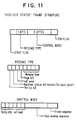
- Fig. 11 shows the structure of the receiver status message. This message is generated by the receiver terminal 28 in response to the "I Need Status" message.
- the message type for this message is 0100.
- the page bit indicates the page status of the receiver memory 42.
- the receiver status bit indicates the status of the receiver terminal 28, error or normal.
- a parity bit is provided for data integrity.
- the control word is composed three bits which indicate the expected frame, seven bits which indicate the expected window, and two bits to ensure data integrity by a checking of parity.
- Fig. 12 illustrates the messages for "Are You There” and "I Am Okay".
- the message types for these messages are 0110 and 0111, respectively.
- a parity bit is added to the message type to ensure data integrity.
- the control word is made up of ten bits which are used as a time stamp to indicate when this message was sent.
- the control word further comprises four bits which are either 0000 or 1111 indicating messages of "Are You There” or “I Am Okay", respectively. This redundancy is used to ensure that the message is interpreted properly.
- Two parity bits are also used in the control word to ensure its integrity. This message is used on power-up to calculate the round-trip loop time and also to validate link continuity during prolonged times of idle link conditions.
- Fig. 13 demonstrates a normal DLC transmission and acknowledgement.
- Tx is abbreviated by Tx and "receive” is abbreviated by Rx.
- Rx receives the transmitter terminal 26 sends a data message with the transmitter status bit equal to 0.
- the receiver receives this message correctly and responds by sending an Ack signal upon the conclusion of the transmission of a sub-window. This same message exchange is repeated every time a sub-window is received correctly.
- Each sub-window is eight frames in this example.
- the sub-window size can be varied based on the BER of the link at that time.
- the system 20 can change the frequency of Ack signals on a frame by frame basis.
- Fig. 14 demonstrates the DLC error recovery mechanism.
- the transmitter terminal 26 initiates a data message with the transmit bit equal to 0.
- the data is received, in this example, incorrectly due to a CRC or sequence error.
- the receiver terminal 28 responds by starting an error message retry timer 82 which may be included within the control logic unit 48 of the receiver terminal 28. Since both of the control units 38 and 48 have the same construction so as to allow for the transmission of data in both directions across the link 30, the timer 82 is shown in the control logic unit 38 of Fig. 3.
- the transmitter terminal 28 responds further by setting the inhibit bit to inhibit the restarting of the timer 82, and sends an error message with the receive status bit set to 0.
- the transmit control unit 38 upon sensing the receive status bit of the error message equal to 0, responds by setting the transmit bit to 1, and initiates an error recovery cycle.
- the transmit terminal 26 reverts to the sub-window and frame specified in the error message and starts transmitting.
- the transmit terminal 26 now sends a data message with the transmit status bit now equal to 1.
- the transmit terminal 26, upon receiving the Ack message resets the transmit status bit to indicate that the "Go BACK" state is complete.
- the transmit terminal 26 continues to send the data packets that follow.
- the next data message has the transmit status bit equal to 0, and when received by the receive terminal 28, resets both the receive status bit and the inhibit bit.
- the error message retry timer 82 is reloaded and disabled until another erroneous data message with the transmit status bit equal to 0 is received.
- the timer 82 is disabled when the receive bit is 1.
- the timer 82 is either restarted, if the data message which reset the receive status bit was incorrect, or is reloaded and disabled if the data received is correct.
- the timer 82 remains disabled until the next erroneous data message is received.
- the control unit 38 would have initiated the message "I Need Status", and started the timer 82 at the transmitter control unit 38 to regulate the time between transmissions of the message "I Need Status".
- the timer 82 is disabled when the transmit status bit is equal to 1, and is restarted when the transmit bit is reset if the condition "Awaiting Ack” still exists.
- the timer 82 is reloaded and disabled when the "Awaiting Ack” condition is alleviated at the transmit terminal 26.
- the transmit and receive status bits, and the inhibit bit are provided as a feature of the invention to ensure that the controlled and efficient algorithm for the "GO BACK' function can be implemented. These bits ensure that the "GO BACK' function is accomplished efficiently.
- the provision, in accordance with the invention, of the transmit and receive status bits allows the transmit terminal 26 and the receive terminal 28 to be synchronized with respect to the specific data frames being communicated without the need for excessively complex (smart) microprocessor at either terminal of the system 20.
- the provision, in accordance with the invention, of the inhibit bit blocks a constant restarting of the error timer with erroneous packet received, this saving power due to excess reloading.
- the foregoing operation of the system 20 is adaptive, the adaptive nature of the DLC allowing the characteristics of the control logic unit 38, as well as of the control logic unit 48, to vary in accordance with the BER of the link 30.
- the error rate may vary due to instability in the power supply of a laser driver employed with an optical configuration of the link 30.
- the throughput performance of the system 20 is characterized by a relatively low bit error rate, no larger than 10 ⁇ 9. Because of the 'GO-BACK" retransmissions, each unsuccessful packet transmission results in a waste of one round trip interval of link bandwidth.
- D be the round trip
- C the link speed in bits per second
- s the packet size
- Fig. 4 depicts a comparison of link throughput efficiency between the GO-BACK-N algorithm and an ideal DLC. It can be seen that for a BER no larger than 10 ⁇ 9, the two forms of control have almost identical performances.
- Fig. 15 is a program flow chart useful in explaining operation of the transmit terminal 26 of Fig. 1.
- the program starts at block 86 by selecting the sub-window and packet size, shown at block 88, for operation of the transmit memory 32.
- the transmit memory 32 is cleared, at block 90, and the status bit for each frame 70 (Fig. 5) in each sub-window 74 is set to WRITE, as shown at block 92, for receipt of data from the user 22 (Fig. 1).
- data from the user 22 is loaded into the transmit memory 32 after which, at block 96, the status bits are changed to READ of the frames which have been filled with data.
- the memory 32 is now ready to output the data to the receive terminal 28 via the link 30.
- Reading out of the data is accomplished, beginning at block 98, by moving a READ pointer to designate the first frame of the sequence of frames from which data is to be transmitted as a packet.
- the data of a frame is transmitted as a data packet via the link 30 to the receive terminal 28.
- data of the next frame and of subsequent frames are transmitted serially in a sequence of packets to complete the transmission of data of all of the frames of a single sub-window.
- the status bits for the respective frames of the sub-window are reset to "Awaiting Acknowledgement", as shown at block 104.
- a request for status is sent at block 106, the request being for an acknowledgement signal. A failure to receive an acknowledgement signal will be dealt with in the program flow chart of Fig. 17.
- the flow chart of Fig. 15 continues at block 108 which is on the second drawing sheet of Fig. 15, the first drawing sheet being identified as Fig. 15A and the second drawing sheet being identified as Fig. 15B. Junction points A, B, and C are provided for joining together the portions of the charts of Figs. 15A and 15B. For example, the chart flows from block 106 to block 108 via the junction point A.
- the transmit terminal 26 checks as to whether the data of the last sub-window has been sent.
- An error counter shown at block 110, is used to measure the frequency of occurrence of transmission errors so as to enable a selection of an appropriate sub-window size at block 88 to attain a desired frequency of acknowledgement signals commensurate with the error rate as has been described hereinabove.
- the operation proceeds to block 112 wherein the counter 110 is read and reset, the contents of the counter 110 being used in selecting the sub-window and packet size at block 88. The cycle of writing in data and reading out data would then be repeated after completion of the successful transmission of data of the last sub-window.
- operation proceeds to block 114 to determine if an error message has been received. If no error message has been received, then the operation proceeds to block 116 wherein the READ pointer is advanced to the next frame of the sub-window from which data is to be transmitted to the receive terminal 28. The operation then reverts to block 100 for transmission of data of the next frame in a data packet.
- the operation proceeds to block 118 in which the READ pointer is moved back to a previously transmitted frame, which frame has been designated in the error message as having not been received at all, or having been received with error.
- This is in accordance with the GO-BACK-N frames algorithm employed in the operation of the invention.
- operation proceeds to block 120 where the status bits in the frame and in the data packet are set to indicate that the data packet is a retransmission of a previously transmitted block of data.
- the operation continues at block 122 for advancing a count of the counter 110 to indicate that an error message has been received.
- the count of the counter 110 For each error message received during the transmission of a complete window of data of the transmit memory 32, the count of the counter 110 is advanced so that, at the conclusion of the transmission of the data of the window, the counter 110 shows the complete count of all error messages received during the transmission of the window data.
- the anticipated data error rate is very low, on the order of one error in 1014 bits. At such a low error rate, it is unlikely that more than one bit would in error in a data packet so that the bit error rate (BER) would be equal to the packet error rate. Therefore, the error counter at block 110, by counting the occurrences of erroneous packets, provides information useful in setting the sub-window size and acknowledgement repetition-frequency parameters suitable for operation in an environment of a specific BER.
- the operation of the receive terminal 28 is described further with the aid of a program flow chart which starts at block 124.
- the receive memory 42 is cleared, and the status bits at each of the frames of the memory 42 are set at block 128 to WRITE for storing data received by the terminal 28 from the terminal 26.
- the receiving of the incoming data packets occurs at block 130 after which, at block 132 the embedded bits designating the sequence number of each packet are examined to ascertain that the packet identifications agree with the memory frames into which the data is to be stored.
- a faulty sequence error could occur, by way of example, in the situation wherein a data packet was not received at the terminal 28 in which case the next packet to be received would appear to have a sequence number higher than the next packet which was anticipated to have been received. If the packet identification number is correct, then, at block 134, the cyclic redundancy check (CRC) accompanying the data in each packet is employed for determining that the data is correct and not corrupted by bit errors.
- CRC cyclic redundancy check
- the operation Upon initiating the GO-BACK process at block 136, the operation proceeds to block 138 wherein the receive terminal 28 sends an error signal to the transmit terminal 26, the error signal including the sequence number of the frame and packet experiencing the transmission failure. Thereupon, operation reverts to block 130 in which incoming data packets are received and examined at block 132 to determine if a retransmitted data packet having the right sequence number has been received. It is noted that there is no confusion between a retransmitted packet and the originally transmitted packet because the control word forming a part of the packet has bits embedded therein which identify the status of a packet as being an originally transmitted packet for a retransmitted packet.
- the operation proceeds to block 140.
- the GO-BACK process is terminated and the status bits at the frames of the receive memory can be set, as will be described now, to enable read-out of data from the memory 42 to the user 24.
- the operation proceeds to block 140 wherein the data is stored in the appropriate frame of the memory 42. It is noted that the frame number and the sequence number of the data packet are equal to insure that the data is stored in the correct frame in synchronism with the frame of the transmit memory 32 having the same identification or sequence number.
- the status bits of the frame are changed, at block 144 to READ to enable read-out of the data to the user 24.
- the receive terminal 28 watches for acknowledgement requests, at block 146, transmitted from the transmit terminal 26. If an Ack request has been received, then an acknowledgement signal, at block 148, is sent from the receive terminal 28 to the transmit terminal 26. If no acquisition request has been received, or if such request has been received and responded to, the operation proceeds to block 150 in which the transmit terminal 28 ascertains whether the last frame of the memory 42 has been filled with data. If the last frame has been filled with data, or if a control word has been received indicating that no further data is to be be transmitted, operation then proceeds to block 152 wherein the data is read out of the memory 42 to the user 24. If, at block 150, the last frame has not been filled, nor has an end of transmission signal been received, then the operation reverts to block 130 for receipt of further incoming data packets.
- Fig. 17 shows an aspect of the operation of the transmit terminal 26 by use of a program flow chart for timing an interval between a request for acknowledgement and receipt of the acknowledgement signal.
- the procedure begins at block 154 for a reading of the status bits of the data frames in the transmit memory 32 of Fig. 1. Upon reading the status bits, it is found at block 156 that the status "Awaiting Ack" may or may not be present. If the "Awaiting Ack" status is not present, operation reverts to a further reading of the status bits at block 154. If the "Awaiting Ack" status is present, operation proceeds to block 158 wherein the transmit terminal 26 sends a request for acknowledgement to the receive terminal 28. Upon requesting the acknowledgement, the timer 82 (Fig. 3) is started at block 160 to measure the time elapsed until an acknowledgement is received from the receive terminal 28.
- the operation continues at block 162 wherein the transmit terminal 26 determines whether an acknowledgement has been received. If the acknowledgement has been received, then the timer 82 is reset at block 164 after which the operation reverts to block 154 for further reading of the status bit. At block 162, if no acknowledgement is received, then a determination is made at block 166 as to whether an error signal has been received at the transmit terminal 26 from the receive terminal 28. If no other signal has been received, the transmit terminal 26 continues to implement a normal transmission of packets at block 168.
- the timer 82 which was started at block 160 continues to run, and at block 172 is read to see if an excessively long time interval has elapsed since the request for acknowledgement at block 158. If an excessively long time has elapsed, then an alarm is activated at block 174 to warn operating personnel at the transmit terminal 26 that the system 20 has malfunctioned and that data may not be reaching the receive terminal 28. Further, at block 176, the upper layer of the system architecture is alerted that the communication link is down, has malfuctioned. If, at block 172, an excessive time has not yet been measured then the operation reverts to block 162 for a further check as to whether the acknowledgement has been received. The operation continues to loop around between blocks 162 and 172 until either an acknowledgement signal is finally received, or until the alarm sounds at block 174 at which point the automatic operation is interrupted by personnel at both of the terminals 26 and 28 to take remedial action.
- the implementation of the architecture and protocol of the invention and the communication system has provided for a rapid speed of data transmission and a rapid speed of data recovery in the event that transmission errors are detected.
- This has been accomplished by arranging for the storage of data packets in transmit and receive memories having the same format of frame structure with identification numbers equal to the sequence numbers of the individual packets.
- the features of the invention have been made possible by the use of status bits and control words embedded within the data packets which provide both terminals with the same information as to the status of a packet to facilitate synchronization by means of hard-wired and programmable array logic units functioning as state machines.
- the state machines are responsive to specific events taking place in the communication system such as the detection of an error and the response of a terminal to the error.
Landscapes
- Engineering & Computer Science (AREA)
- Computer Networks & Wireless Communication (AREA)
- Signal Processing (AREA)
- Quality & Reliability (AREA)
- Communication Control (AREA)
- Data Exchanges In Wide-Area Networks (AREA)
Claims (16)
- Verfahren des adaptiven Steuerns einer Kommunikationsverbindung (30), um eine Fehlerschwankung bei einer Übertragung von Daten von einer ersten Datenstation (26) zu einer zweiten Datenstation (28) auszugleichen, wobei das Verfahren folgendes umfaßt:Speichern von Daten an der ersten Datenstation (26) in einem Übertragungsspeicher (32) als eine Feldgruppe von Datenrahmen (70), die in einem Fenster des Übertragungsspeichers (32) angeordnet ist;Aufteilen des Fensters (72) in Teilfenster (74), von denen jedes weniger Rahmen (70) als das Fenster (72) aufweist;Übertragen von Daten von aufeinanderfolgenden der Rahmen (70) in einer Folge von Paketen, wobei Daten in einem Paket von einem Rahmen (70) erhalten werden;Einbetten von Steuersignalen in jedes der Pakete, wobei die Steuersignale Pakete durch die Folgenummer kennzeichnen;Empfangen der Pakete (130) an der Datenstation (28);Prüfen der Pakete durch Tests nach Folgenummer (132) und Bitfehler (134) zur Feststellung eines Übertragungsfehlers;Speichern von Daten (142) von nur den Paketen, welche die Tests bestehen, in einem Empfangsspeicher (42) an der zweiten Datenstation (28), Pakete, die bei mindestens einem der Tests scheitern, werden zurückgewiesene Pakete;Neuübertragen zurückgewiesener Pakete von der ersten Datenstation (26) zu der zweiten Datenstation (28);Zählen der Anzahl zurückgewiesener Pakete, die während einer Übertragung eines Fensters von Daten auftreten, um eine Paketfehlerrate zu erhalten;Senden eines Anforderungssignals nach Bestätigung von der ersten Datenstation (26) zu der zweitem Datenstation (28); undÄndern der Frequenz der Anforderungssignale nach Bestätigung gemäß der Paketfehlerrate, um die Verzögerung der Neuübertragung zu minimieren und die Auslastung der Verbindung (30) zu erhöhen.
- Verfahren gemäß Anspruch 1, das weiterhin einen Schritt des Zurückmeldens eines Fehlersignals von der zweiten Datenstation (28) an die erste Datenstation (26) umfaßt, das die Folgenummer eines zurückgewiesenen Paketes (138) bezeichnet.
- Verfahren gemäß Anspruch 2, wobei während des Schrittes des Übertragens eine Neuübertragung von Paketen (170), die nach dem zurückgewiesenen Paket übertragen wurden, gemäß einem GO-BACK-Algorithmus stattfindet.
- Verfahren gemäß Anspruch 1, wobei das Ändern der Frequenz der Anforderungssignale nach Bestätigung durch das Schwanken der Anzahl von Rahmen zwischen zwei Anforderungssignalen nach Bestätigung ausgeführt wird.
- Verfahren gemäß Anspruch 1, wobei während des Schrittes des Neuübertragens ein Schritt des Einbettens eines Steuerbits (120) in jedes Paket (130) auftritt, das jedes Paket (130) als ein neuübertragenes Paket kennzeichnet.
- Verfahren gemäß Anspruch 1, wobei der Schritt des Sendens eines Anforderungssignals nach dem Abschluß der Übertragung aller Rahmen (70) eines Teilfensters (74) ausgeführt wird und wobei das Anforderungssignal als ein Teil des Steuersignals in ein anschließend übertragenes Paket eingebettet wird.
- Verfahren gemäß Anspruch 1, das weiterhin einen Schritt des Zurückmeldens eines Bestätigungssignals (148) von der zweiten Datenstation (28) an die erste Datenstation (26) umfaßt, welches bestätigt, daß Pakete, die vorher an der zweiten Datenstation (28) empfangen wurden, die Tests (132, 134) bestanden haben.
- Verfahren gemäß Anspruch 7, das weiterhin einen Schritt des Festlegenseines Zeitintervalls (160) umfaßt, das zwischen dem Anforderungssignal nach Bestätigung und dem Empfang eines Bestätigungssignals (162) abläuft.
- Verfahren gemäß Anspruch 8, wobei die Festlegung des Intervalls die Zeit einschließt, die zur Neuübertragung eines zurückgewiesenen Paketes abgelaufen ist, und wobei nach Feststellung eines Übertragungsfehlers, der von einer Neuübertragung gefolgt wird, der Neuübertragung die Bestätigung folgt.
- Verfahren gemäß Anspruch 1, wobei die Folgenummer gleich der Nummer des Rahmens (70) in dem Fenster ist, das Daten des Paketes enthält, das die Folgenummer trägt.
- Verfahren gemäß Anspruch 10, wobei Daten des Empfangsspeichers (42) in einer Feldgruppe von Rahmen (70) in einem Fenster (72) des Empfangsspeichers gespeichert werden, die mit der Feldgruppe von Rahmen (70) in dem Fenster des Über-tragungsspeichers (32) identisch ist.
- Verfahren gemäß Anspruch 1, wobei der Schritt des Änderns der Größen der Teil fenster (74) gemäß der Paketfehlerrate verwendet wird, um eine Geschwindigkeit der Datenübertragung über die Kommunikationsverbindung (30) zu maximieren; und wobei das Verfahren weiterhin folgendes umfaßt:Zurückmelden eines Fehlersignals von der zweiten Datenstation (28) an die erste Datenstation (26), das die Folgenummer eines zurückgewiesenen Paketes bezeichnet;wobei während des Schrittes des Übertragens eine Neuübertragung von Paketen (170), die nach dem zurückgewiesenen Paket übertragen wurden, gemäß einen GO-BACK-Algorithmus (118) stattfindet;während des Schrittes des Neuübertragens ein Schritt des Einbettens eines Steuersignals (120) in jedes Paket stattfindet, das jedes Paket als ein neuübertragenes Paket kennzeichnet;die Folgenummer gleich der Nummer des Rahmens (70) in dem Fenster ist, das Daten des Paketes enthält, das die Folgenummer trägt; undDaten des Empfangsspeichers (42) in einer Feldgruppe von Rahmen (70) in einem Fenster (72) des Empfangsspeichers (42) gespeichert werden, die mit der Feldgruppe von Rahmen (70) in dem Fenster des Übertragungsspeichers (32) identisch ist.
- Verfahren gemäß Anspruch 12, wobeinach dem Abschluß der Übertragung aller Rahmen (70) eines Teilfensters (74) ein Schritt des Sendens eines Anforderungssignals nach Bestätigung von der ersten Datenstation (26) an die zweite Datenstation (28) stattfindet, wobei das Anforderungssignal als ein Teil des Steuersignals in ein anschließend übertragenes Paket eingebettet wird; wobei das Verfahren weiterhin einen Schritt des Zurückmeldens eines Bestätigungssignals (148) von der zweiten Datenstation (28) an die erste Datenstation (26) umfaßt, welches bestätigt, daß Pakete, die vorher an der zweiten Datenstation (28) empfangen wurden, die Tests (132, 134) bestanden haben.
- Verfahren des adaptiven Steuerns einer Kommunikationsverbindung (30), um eine Fehlerschwankung bei einer Übertragung von Daten von einer ersten Datenstation (26) zu einer zweiten Datenstation (28) auszugleichen, wobei das Verfahren folgendes umfaßt:Speichern von Daten an der ersten Datenstation (26) in einem Übertragungsspeicher (32) als eine Feldgruppe von Datenrahmen (70), die in einem Fenster des Übertragungsspeichers (32) angeordnet sind;Aufteilen des Fensters (72) in Teilfenster (74), von denen jedes weniger Rahmen (70) als das Fenster (72) aufweist;Übertragen von Daten von aufeinanderfolgenden der Rahmen (70) in einer Folge von Paketen, wobei Daten in einem Paket von einem Rahmen (70) erhalten werden;Einbetten von Steuersignalen in jedes der Pakete, wobei die Steuersignale Pakete durch die Folgenummer kennzeichnen;Empfangen der Pakete (130) an der Datenstation (28);Prüfen der Pakete durch Tests nach Folgenummer (132) und Bitfehler (134) zur Feststellung eines Übertragungsfehlers;Speichern von Daten (142) von nur den Paketen, welche die Tests bestehen, in einem Empfangsspeicher (42) an der zweiten Datenstation (28), wohei Pakete, die bei mindestens einem der Tests scheitern, zurückgewiesene Pakete sind;Neuübertragen zurückgewiesener Pakete von der ersten Datenstation (26) an die zweite Datenstation (28);Zurückmelden eines Fehlersignals von der zweiten Datenstation an die erste Datenstation, das die Folgenummer eines zurückgewiesenen Paketes bezeichnet;Zählen der Anzahl von Fehlersignalen, die während der Übertragung eines Fensters von Daten auftreten, um eine Paketfehlerrate zu erhalten;wobei die Folgenummer gleich der Nummer des Rahmens (70) in dem Fenster ist, das Daten des Paketes enthält, das die Folgenummer trägt;Daten des Empfangsspeichers (42) werden in einer Feldgruppe von Rahmen (70) in einem Fenster (72) des Empfangsspeichers (42) gespeichert, die mit der Feldgruppe von Rahmen (70) in dem Fenster des Übertragungsspeichers (32) identisch ist;nach dem Abschluß der Übertragung aller Rahmen (70) eines Teilfensters (74) ein Schritt des Sendens eines Anforderungssignals nach Bestätigung von der ersten Datenstation (26) an die zweite Datenstation (28) stattfindet, wobei das Anforderungssignal als ein Teil des Steuersignals in ein anschließend übertragenes Paket eingebettet wird;wobei das Verfahren weiterhin das Zurückmelden eines Bestätigungssignals (148) von der zweiten Datenstation (28) an die erste Datenstation (26) umfaßt, welches bestätigt, daß Pakete,die vorher an der zweiten Datenstation (28) empfangen wurden, die Tests (132, 134) bestanden haben; undwobei ein Fehlersignal durch Vergleichen von Folgenummern gespeicherter Daten in dem Empfangsspeicher (42) mit Rahmennummern von Rahmen (70), welche Daten speichern, erzeugt wird;wobei das Verfahren weiterhin einen Schritt des Änderns einer Wiederholfrequenz der Bestätigungsanforderungssignale gemäß der Paketfehlerrate umfaßt, um eine Geschwindigkeit der Datenübertragung über die Kommunikationsverbindung (30) zu maximieren.
- Verfahren des adaptiven Steuerns einer Kommunikationsverbindung (30), um eine Fehlerschwankung bei einer Übertragung von Daten von einer ersten Datenstation (26) an eine zweite Datenstation (28) auszugleichen, wobei das Verfahren folgendes umfaßt:Übertragen einer Folge von Datenpaketen von der ersten Datenstation (26) an die zweite Datenstation (28), um an der zweiten Datenstation empfangen zu werden;Senden eines Anforderungssignals von der ersten Datenstation (26) nach Bestätigung des Empfangs der Datenpakete durch die zweite Datenstation (28), wobei das Senden periodisch nach einer vorherbestimmten Anzahl von Datenpaketen erfolgt;Zurückmelden eines Antwortsignals als Antwort auf das Bestätigungsanforderungssignal von der zweiten Datenstation (28) an die erste Datenstation (26), das den Empfang fehlerfreier Pakete bestätigt, wobei das Antwortsignal im Fall des Empfangs eines fehlerhaften Paketes ein Fehlersignal ist;Neuübertragen von Paketen, die mit Fehler empfangen wurden, gemäß einem GO-BACK-Algorithmus;Formulieren einer Paketfehlerrate durch Vergleichen der Anzahl der Fehlersignale mit der Anzahl der übertragenen Pakete; undÄndern einer Wiederholfrequenz der Bestätigungsanforderungssignale gemäß der Paketfehlerrate, wobei eine Erhöhung der Fehlerrate eine Erhöhung der Wiederholfrequenz erzeugt, um die Übertragungsgeschwindigkeit einer Folge von Datenpaketen zu erhöhen.
- Verfahren gemäß Anspruch 15, das weiterhin folgendes umfaßt:Kennzeichnen jedes Paketes mit einer Folgenummer;Ablehnen eines Paketes mit einem Fehler;Zurückmelden eines Fehlersignals von der zweiten Datenstation (28) an die erste Datenstation (26), das die Folgenummer eines zurückgewiesenen Paketes bezeichnet;Einbetten von Steuersignalen in jedes der Pakete, wobei die Steuersignale Pakete durch die Folgenummer kennzeichnen; undwobei während des Schrittes des Neuübertragens ein Schritt des Einbettens eines Steuersignals in jedes Paket stattfindet, das jedes Paket als ein neuübertragenes Paket kennzeichnet.
Applications Claiming Priority (2)
| Application Number | Priority Date | Filing Date | Title |
|---|---|---|---|
| US294086 | 1989-01-05 | ||
| US07/294,086 US4970714A (en) | 1989-01-05 | 1989-01-05 | Adaptive data link protocol |
Publications (3)
| Publication Number | Publication Date |
|---|---|
| EP0377136A2 EP0377136A2 (de) | 1990-07-11 |
| EP0377136A3 EP0377136A3 (de) | 1991-10-30 |
| EP0377136B1 true EP0377136B1 (de) | 1996-03-13 |
Family
ID=23131820
Family Applications (1)
| Application Number | Title | Priority Date | Filing Date |
|---|---|---|---|
| EP89122802A Expired - Lifetime EP0377136B1 (de) | 1989-01-05 | 1989-12-11 | Adaptives Datenübertragungsprotokoll |
Country Status (4)
| Country | Link |
|---|---|
| US (1) | US4970714A (de) |
| EP (1) | EP0377136B1 (de) |
| JP (1) | JP2503086B2 (de) |
| DE (1) | DE68925958T2 (de) |
Cited By (1)
| Publication number | Priority date | Publication date | Assignee | Title |
|---|---|---|---|---|
| DE102004015159A1 (de) * | 2004-03-27 | 2006-01-19 | Deutsche Thomson-Brandt Gmbh | Verfahren zum Synchronisieren von Speicherbereichen in einer Sendervorrichtung und einer Empfängervorrichtung sowie Empfängervorrichtung |
Families Citing this family (136)
| Publication number | Priority date | Publication date | Assignee | Title |
|---|---|---|---|---|
| US5175766A (en) * | 1988-12-09 | 1992-12-29 | The Exchange System Limited Partnership | Signalling scheme for controlling data encryption device in an electronic fund transaction processing system |
| EP0453863A2 (de) * | 1990-04-27 | 1991-10-30 | National Semiconductor Corporation | Verfahren und Gerät zur Ausführung einer Mediumzugriffssteuerung/Wirtsystemschnittstelle |
| JP2652079B2 (ja) * | 1990-08-09 | 1997-09-10 | シャープ株式会社 | データ伝送装置 |
| JP2763394B2 (ja) * | 1990-10-09 | 1998-06-11 | 三菱電機株式会社 | 通信制御装置 |
| AU8636391A (en) * | 1990-10-10 | 1992-05-20 | British Telecommunications Public Limited Company | Network traffic management |
| JP2615509B2 (ja) * | 1990-10-30 | 1997-05-28 | 富士通株式会社 | 通信装置 |
| US5335233A (en) * | 1990-12-31 | 1994-08-02 | International Business Machines Corporation | Data packet format |
| DE69220262T2 (de) * | 1991-03-08 | 1997-09-18 | Matsushita Electric Ind Co Ltd | Einrichtung zur Datenübertragung |
| US7936664B2 (en) | 1991-03-26 | 2011-05-03 | Nokia Corporation | Multi-carrier radio link protocol supervision in a radio communication system |
| US7298701B2 (en) * | 2002-10-31 | 2007-11-20 | Nokia Corporation | Apparatus, and associated method, for requesting data retransmission in a packet radio communication system |
| JP2995348B2 (ja) * | 1991-03-28 | 1999-12-27 | マツダ株式会社 | 多重伝送方法 |
| US5361255A (en) * | 1991-04-29 | 1994-11-01 | Dsc Communications Corporation | Method and apparatus for a high speed asynchronous transfer mode switch |
| US5894547A (en) * | 1991-06-27 | 1999-04-13 | International Business Machines Corporation | Virtual route synchronization |
| US5307351A (en) * | 1991-08-26 | 1994-04-26 | Universal Data Systems, Inc. | Data communication apparatus for adjusting frame length and method of operating same |
| US5257384A (en) * | 1991-09-09 | 1993-10-26 | Compaq Computer Corporation | Asynchronous protocol for computer system manager |
| US5490250A (en) * | 1991-12-31 | 1996-02-06 | Amdahl Corporation | Method and apparatus for transferring indication of control error into data path of data switcher |
| CA2081505C (en) * | 1992-02-14 | 1998-09-01 | Charles Robert Kalmanek, Jr. | Packet framer |
| US5455831A (en) * | 1992-02-20 | 1995-10-03 | International Business Machines Corporation | Frame group transmission and reception for parallel/serial buses |
| US5267240A (en) * | 1992-02-20 | 1993-11-30 | International Business Machines Corporation | Frame-group transmission and reception for parallel/serial buses |
| US5455830A (en) * | 1992-02-20 | 1995-10-03 | Gregg; Thomas A. | Error detection and recovery in parallel/serial buses |
| CA2064541C (en) * | 1992-03-31 | 1998-09-15 | Thomas A. Gray | Cycling error count for link maintenance |
| US5260933A (en) * | 1992-05-15 | 1993-11-09 | International Business Machines Corporation | Acknowledgement protocol for serial data network with out-of-order delivery |
| US5442637A (en) * | 1992-10-15 | 1995-08-15 | At&T Corp. | Reducing the complexities of the transmission control protocol for a high-speed networking environment |
| US6151689A (en) * | 1992-12-17 | 2000-11-21 | Tandem Computers Incorporated | Detecting and isolating errors occurring in data communication in a multiple processor system |
| US5386518A (en) * | 1993-02-12 | 1995-01-31 | Hughes Aircraft Company | Reconfigurable computer interface and method |
| US5588009A (en) * | 1994-02-03 | 1996-12-24 | Will; Craig A. | Personal paging, communications, and locating system |
| US5479408A (en) * | 1994-02-22 | 1995-12-26 | Will; Craig A. | Wireless personal paging, communications, and locating system |
| US5515385A (en) * | 1994-03-09 | 1996-05-07 | Motorola, Inc. | Device and method for limiting delay by substantial elimination of duplicate synchronous data frames in a communication system |
| US5467341A (en) * | 1994-04-14 | 1995-11-14 | Toshiba America Information Systems, Inc. | Apparatus and method for alerting computer users in a wireless LAN of a service area transition |
| JP2611667B2 (ja) * | 1994-07-27 | 1997-05-21 | 日本電気株式会社 | 異種フレーム形式混在通信システム |
| US5422893A (en) * | 1994-08-04 | 1995-06-06 | International Busines Machines Corporation | Maintaining information from a damaged frame by the receiver in a communication link |
| US6108809A (en) * | 1994-11-11 | 2000-08-22 | Siemens Aktiengesellschaft | Method for sending messages from a lower-level controller to a higher-level controller |
| US5526353A (en) * | 1994-12-20 | 1996-06-11 | Henley; Arthur | System and method for communication of audio data over a packet-based network |
| US5581566A (en) * | 1995-01-06 | 1996-12-03 | The Regents Of The Univ. Of California Office Of Technology Transfer | High-performance parallel interface to synchronous optical network gateway |
| US5602831A (en) * | 1995-03-31 | 1997-02-11 | Seiko Communications Systems, Inc. | Optimizing packet size to eliminate effects of reception nulls |
| US5987505A (en) * | 1995-04-28 | 1999-11-16 | Fry; Shawn C. | Method for emulation of terminal-resident GUI application by transmitting macros having information and command instructing the terminal how to process the information |
| US5727154A (en) * | 1995-04-28 | 1998-03-10 | Fry; Shawn C. | Program synchronization on first and second computers by determining whether information transmitted by first computer is an acceptable or unacceptable input to second computer program |
| FI98174C (fi) * | 1995-05-09 | 1997-04-25 | Nokia Telecommunications Oy | Datansiirtojärjestelmä, jossa on liukuvaan ikkunaan perustuva datavuonohjaus |
| GB2301752B (en) * | 1995-06-02 | 2000-03-29 | Dsc Communications | Control message transmission in telecommunications systems |
| US5664091A (en) * | 1995-08-31 | 1997-09-02 | Ncr Corporation | Method and system for a voiding unnecessary retransmissions using a selective rejection data link protocol |
| US5748100A (en) * | 1995-10-06 | 1998-05-05 | Motorola, Inc. | Reliable wireless message distribution system |
| US5717689A (en) * | 1995-10-10 | 1998-02-10 | Lucent Technologies Inc. | Data link layer protocol for transport of ATM cells over a wireless link |
| US5768294A (en) * | 1995-12-11 | 1998-06-16 | International Business Machines Corporation | Memory implemented error detection and correction code capable of detecting errors in fetching data from a wrong address |
| US5745685A (en) * | 1995-12-29 | 1998-04-28 | Mci Communications Corporation | Protocol extension in NSPP using an acknowledgment bit |
| SE515264C2 (sv) * | 1996-02-12 | 2001-07-09 | Telia Ab | Metod att koppla datatjänster för GSM |
| US5799211A (en) * | 1996-03-22 | 1998-08-25 | General Electric Company | Shift register having latch cell operable in serial-in/parallel-out and parallel-in/serial-out modes in response to a sequence of commands for controlling appropriate switches |
| US6055576A (en) * | 1996-05-20 | 2000-04-25 | Intel Corporation | Access control to packet transfer based on key match stored in cable modem hardware unit |
| JPH09321799A (ja) * | 1996-05-27 | 1997-12-12 | Fuji Xerox Co Ltd | データ伝送装置および方法 |
| US5825770A (en) * | 1996-06-06 | 1998-10-20 | Northern Telecom Limited | Multiple algorithm processing on a plurality of digital signal streams via context switching |
| US6064673A (en) * | 1996-08-02 | 2000-05-16 | 3Com Corporation | Communications system having distributed control and real-time bandwidth management |
| KR100200217B1 (ko) * | 1996-10-30 | 1999-06-15 | 윤종용 | 오동작을 방지할 수 있는 다기능 일체형 복합전자제품 및 오동작 방지방법 |
| GB9622683D0 (en) * | 1996-10-31 | 1997-01-08 | Sgs Thomson Microelectronics | Message protocol |
| FR2759518B1 (fr) * | 1997-02-07 | 1999-04-23 | France Telecom | Procede et dispositif d'allocation de ressources dans un reseau numerique de transmission par paquets |
| US5923840A (en) * | 1997-04-08 | 1999-07-13 | International Business Machines Corporation | Method of reporting errors by a hardware element of a distributed computer system |
| US5968189A (en) * | 1997-04-08 | 1999-10-19 | International Business Machines Corporation | System of reporting errors by a hardware element of a distributed computer system |
| DE19722433A1 (de) * | 1997-05-28 | 1998-12-03 | Siemens Ag | Verfahren und Vorrichtung zur Übertragung eines kontinuierlichen Datenstroms in paketierter Form |
| US6021124A (en) * | 1997-08-19 | 2000-02-01 | Telefonaktiebolaget Lm Ericsson | Multi-channel automatic retransmission query (ARQ) method |
| US6134237A (en) * | 1997-09-30 | 2000-10-17 | Motorola, Inc. | Method and apparatus for tracking data packets in a packet data communication system |
| DE19743170A1 (de) * | 1997-09-30 | 1999-04-01 | Daimler Benz Ag | Kommunikationssystem |
| US5961626A (en) * | 1997-10-10 | 1999-10-05 | Motorola, Inc. | Method and processing interface for transferring data between host systems and a packetized processing system |
| DE19824143A1 (de) * | 1998-05-29 | 1999-12-02 | Siemens Ag | Verfahren zur Datenübertragung und Kommunikationssystem |
| US6192410B1 (en) * | 1998-07-06 | 2001-02-20 | Hewlett-Packard Company | Methods and structures for robust, reliable file exchange between secured systems |
| US6359877B1 (en) * | 1998-07-21 | 2002-03-19 | Telefonaktiebolaget Lm Ericsson (Publ) | Method and apparatus for minimizing overhead in a communication system |
| US6125116A (en) * | 1998-07-27 | 2000-09-26 | Nec Corporation | Message sets for a flexible programmable ATM access multiplexer using functional separation of line and protocol related functions |
| US7058027B1 (en) | 1998-09-16 | 2006-06-06 | Scientific Research Corporation | Systems and methods for asynchronous transfer mode and internet protocol |
| DE69820444T2 (de) * | 1998-10-05 | 2004-05-27 | Mitsubishi Electric Information Technology Centre Europe B.V. | Automatische WiederholungsanforderungsProtokoll der "go-back-N" Art über virtuellen Verbindungen |
| US6212195B1 (en) | 1998-12-01 | 2001-04-03 | 3Com Corporation | Telecommunication apparatus and method for forwarding packets using separate collision domains |
| US6262979B1 (en) | 1998-12-01 | 2001-07-17 | 3Com Corporation | Telecommunication conferencing system and method |
| US6967963B1 (en) | 1998-12-01 | 2005-11-22 | 3Com Corporation | Telecommunication method for ensuring on-time delivery of packets containing time-sensitive data |
| US6654375B1 (en) * | 1998-12-24 | 2003-11-25 | At&T Corp. | Method and apparatus for time-profiling T-carrier framed service |
| US6633574B1 (en) * | 1999-03-17 | 2003-10-14 | Loytec Electronics Gmbh | Dynamic wait acknowledge for network protocol |
| US6335933B1 (en) * | 1999-05-21 | 2002-01-01 | Broadcom Homenetworking, Inc. | Limited automatic repeat request protocol for frame-based communication channels |
| US6625128B1 (en) * | 1999-06-28 | 2003-09-23 | Legerity, Inc. | Method and apparatus for prioritizing packet data transmission and reception |
| US6393435B1 (en) | 1999-09-22 | 2002-05-21 | International Business Machines, Corporation | Method and means for evaluating the performance of a database system referencing files external to the database system |
| US6970450B1 (en) * | 1999-10-29 | 2005-11-29 | Array Telecom Corporation | System, method and computer program product for point-to-point bandwidth conservation in an IP network |
| JP2001142845A (ja) * | 1999-11-17 | 2001-05-25 | Toshiba Corp | コンピュータシステムおよびデータ転送制御方法 |
| DE60031090T2 (de) | 2000-03-22 | 2007-04-05 | Alcatel | Verfahren und Vorrichtung zur Wiederzusammensetzung von Rahmen |
| US6745360B1 (en) * | 2000-04-13 | 2004-06-01 | Microsoft Corporation | Method and system for controlling the rate of acknowledgment of communication packets |
| US6925502B1 (en) * | 2000-06-20 | 2005-08-02 | At&T Corp. | Methods and systems for improving data transmission rates having adaptive protocols |
| JP4330767B2 (ja) * | 2000-06-26 | 2009-09-16 | 株式会社エヌ・ティ・ティ・ドコモ | 自動再送要求を行う通信方法及び基地局装置 |
| EP1209861A1 (de) * | 2000-11-22 | 2002-05-29 | Telefonaktiebolaget L M Ericsson (Publ) | Überwachung des Datenverkehrs in Paketnetzwerken |
| US6999430B2 (en) * | 2000-11-30 | 2006-02-14 | Qualcomm Incorporated | Method and apparatus for transmitting data traffic on a wireless communication channel |
| DE10102053A1 (de) * | 2001-01-17 | 2002-07-18 | Merck Patent Gmbh | Piperazinylcarbonylchinoline und -isochinoline |
| US7145704B1 (en) | 2003-11-25 | 2006-12-05 | Cheetah Omni, Llc | Optical logic gate based optical router |
| US7120134B2 (en) * | 2001-02-15 | 2006-10-10 | Qualcomm, Incorporated | Reverse link channel architecture for a wireless communication system |
| GB2375001A (en) * | 2001-04-06 | 2002-10-30 | Motorola Inc | Re-transmission protocol |
| CN1317841C (zh) * | 2001-09-26 | 2007-05-23 | 西门子公司 | 利用置换电报识别错误和避免错误的方法和节点 |
| DE50114373D1 (de) * | 2001-10-31 | 2008-11-13 | Infineon Technologies Ag | Datenübertragungseinrichtung |
| US7110671B1 (en) * | 2001-12-03 | 2006-09-19 | Cheetah Omni, Llc | Method and apparatus for scheduling communication using a star switching fabric |
| US7034975B1 (en) | 2001-12-03 | 2006-04-25 | Cheetah Onmi, Llc | High speed MEMS device |
| US7209657B1 (en) | 2001-12-03 | 2007-04-24 | Cheetah Omni, Llc | Optical routing using a star switching fabric |
| US7260655B1 (en) | 2001-12-03 | 2007-08-21 | Cheetah Omni, Llc | Optical routing using star switching fabric with reduced effective switching time |
| US6912667B1 (en) * | 2002-03-08 | 2005-06-28 | Applied Micro Circuits Corporation | System and method for communicating fault type and fault location messages |
| KR100434054B1 (ko) * | 2002-04-26 | 2004-06-04 | 엘지전자 주식회사 | 래디오 링크 콘트롤의 폴링방법 |
| JP2003346273A (ja) * | 2002-05-30 | 2003-12-05 | Okuma Corp | センサー装置およびセンサー装置の検出データを用いて制御対象を制御するシステムの監視方法 |
| US7082479B2 (en) * | 2002-06-19 | 2006-07-25 | Eastman Kodak Company | System and method for maintaining synchronized data transfer using a plurality of different control words individually indicative of the same single event |
| ATE429116T1 (de) * | 2002-11-07 | 2009-05-15 | Ericsson Telefon Ab L M | Papr-reduktion |
| MXPA05008085A (es) * | 2003-02-12 | 2005-09-21 | Matsushita Electric Industrial Co Ltd | Aparato de recepcion y metodo de recepcion. |
| KR100568232B1 (ko) * | 2003-07-28 | 2006-04-07 | 삼성전자주식회사 | 모바일 애드 혹 네트워크에서 전송층을 이용한 효율적인데이터 송수신 방법 및 상기 방법을 이용한 네트워크 장치 |
| JP4188774B2 (ja) * | 2003-08-14 | 2008-11-26 | 株式会社エヌ・ティ・ティ・ドコモ | フレーム送受信システム、フレーム送信装置、フレーム受信装置、及びフレーム送受信方法 |
| TWI220614B (en) * | 2003-10-21 | 2004-08-21 | Benq Corp | Method and device for updating frame number and automatically generating frame boundary |
| JP4537410B2 (ja) * | 2003-12-29 | 2010-09-01 | エレクトロニクス アンド テレコミュニケーションズ リサーチ インスチチュート | 移動通信システムにおける自動再送要求のためのフィードバックメッセージ生成方法 |
| JP4417733B2 (ja) * | 2004-01-15 | 2010-02-17 | ソニー・エリクソン・モバイルコミュニケーションズ株式会社 | 伝送方法及び装置 |
| KR100714675B1 (ko) * | 2004-01-30 | 2007-05-07 | 삼성전자주식회사 | 데이터 프레임 재전송 방법 및 상기 방법을 사용하는네트워크 장치 |
| US7340667B2 (en) * | 2004-05-10 | 2008-03-04 | Via Telecom Co., Ltd. | Method and/or apparatus implemented in hardware to discard bad logical transmission units (LTUs) |
| US8929228B2 (en) * | 2004-07-01 | 2015-01-06 | Honeywell International Inc. | Latency controlled redundant routing |
| KR100620687B1 (ko) * | 2004-08-17 | 2006-09-19 | 주식회사 팬택앤큐리텔 | 위치기반 단문메시지 시스템 및 위치기반 메시지 생성방법및 위치기반 메시지 표시방법 |
| JP4474266B2 (ja) * | 2004-11-29 | 2010-06-02 | ソニー株式会社 | 情報処理装置、情報処理システム、および情報処理方法、並びにコンピュータ・プログラム |
| US20060227729A1 (en) * | 2005-04-12 | 2006-10-12 | Honeywell International Inc. | Wireless communication system with collision avoidance protocol |
| US7831882B2 (en) | 2005-06-03 | 2010-11-09 | Rambus Inc. | Memory system with error detection and retry modes of operation |
| US9459960B2 (en) | 2005-06-03 | 2016-10-04 | Rambus Inc. | Controller device for use with electrically erasable programmable memory chip with error detection and retry modes of operation |
| US20070011554A1 (en) * | 2005-06-27 | 2007-01-11 | Intel Corporation | Block acknowledgement request apparatus, systems, and methods |
| US7324922B2 (en) * | 2005-10-26 | 2008-01-29 | International Business Machines Corporation | Run-time performance verification system |
| US7562285B2 (en) | 2006-01-11 | 2009-07-14 | Rambus Inc. | Unidirectional error code transfer for a bidirectional data link |
| US8352805B2 (en) | 2006-05-18 | 2013-01-08 | Rambus Inc. | Memory error detection |
| US20070271495A1 (en) * | 2006-05-18 | 2007-11-22 | Ian Shaeffer | System to detect and identify errors in control information, read data and/or write data |
| US8132068B2 (en) * | 2006-06-01 | 2012-03-06 | Innovative Sonic Limited | Dual receiving window method and apparatus for automatic retransmission request |
| US8074139B2 (en) * | 2006-06-27 | 2011-12-06 | Panasonic Corporation | Communication method and communication device |
| JP4841353B2 (ja) * | 2006-08-02 | 2011-12-21 | 富士通株式会社 | データ通信方式 |
| JP2008098798A (ja) * | 2006-10-10 | 2008-04-24 | Nec Corp | 通信システムにおけるデータ伝送状況判定方法および通信装置 |
| EP1936853B1 (de) * | 2006-12-20 | 2018-11-21 | Panasonic Intellectual Property Corporation of America | Vermeidung von Feedbackkollisionen in Mobilkommunikationen |
| US8964734B2 (en) * | 2007-07-26 | 2015-02-24 | The Directv Group, Inc. | Method and system for communicating content having modified packet headers through a satellite |
| US9564988B2 (en) * | 2007-07-26 | 2017-02-07 | The Directv Group, Inc. | Method and system for forming a formatted content stream and using a cyclic redundancy check |
| TWI350457B (en) * | 2007-09-19 | 2011-10-11 | Htc Corp | Data transmission method and system |
| US8964560B2 (en) * | 2007-10-11 | 2015-02-24 | Nokia Solutions And Networks Oy | Apparatus, method, computer program product and system for requesting acknowledgment of transmitted data packets |
| EP2083552A1 (de) * | 2008-01-28 | 2009-07-29 | Alcatel Lucent | Verfahren für den erweiterten Datentransfer, zugehörige Vorrichtung, sowie Programmmodul dafür |
| KR101627538B1 (ko) | 2008-08-11 | 2016-06-07 | 후쿠토메 히로후미 | 리그닌 분해용 촉매, 알코올류 및 유기산류의 제조 방법, 리그닌 분해 생성물의 제조 방법, 방향족 탄화수소 분해용 촉매, 수소 이온의 유리 방법, 그리고 포르피린 |
| US8289996B2 (en) * | 2008-08-20 | 2012-10-16 | Alcatel Lucent | Multi-purpose PDU container for delineating PDU datagrams and PDU datagram attributes in an 8B/10B coded system |
| EP2178236A1 (de) * | 2008-10-14 | 2010-04-21 | Thomson Licensing | Verfahren und Vorrichtung zur Kommunikation unter Verwendung eines einstellbaren Gruppenbestätigungsprotokolls |
| KR101124066B1 (ko) * | 2008-12-03 | 2012-04-12 | 한국전자통신연구원 | 왕복 지연시간이 긴 시스템에서의 arq와 harq의 상호작용 방법 |
| DE102010028485B4 (de) * | 2010-05-03 | 2024-05-29 | Robert Bosch Gmbh | Verfahren und Vorrichtung zur Absicherung von über eine Schnittstelle zu übertragenden Datenpaketen |
| US8976814B2 (en) | 2011-12-09 | 2015-03-10 | General Electric Company | Method of transporting data from sending node to destination node |
| US10247557B2 (en) * | 2014-09-30 | 2019-04-02 | Here Global B.V. | Transmitting map data images in a limited bandwidth environment |
| WO2019190866A1 (en) | 2018-03-26 | 2019-10-03 | Rambus Inc. | Command/address channel error detection |
| CN114629599B (zh) * | 2022-03-10 | 2023-12-19 | 深圳市云语科技有限公司 | 一种实时传输协议的确认报文方法 |
| CN115941128B (zh) * | 2022-11-07 | 2024-09-20 | 天津津航计算技术研究所 | 一种基于QCache的报文协议超时重发管理方法 |
Family Cites Families (8)
| Publication number | Priority date | Publication date | Assignee | Title |
|---|---|---|---|---|
| FR2268411B1 (de) * | 1974-04-17 | 1978-12-01 | Radio Diffusion Tv Francaise | |
| US4527267A (en) * | 1982-07-09 | 1985-07-02 | At&T Bell Laboratories | Method of administering local and end-to-end acknowledgments in a packet communication system |
| US4677614A (en) * | 1983-02-15 | 1987-06-30 | Emc Controls, Inc. | Data communication system and method and communication controller and method therefor, having a data/clock synchronizer and method |
| JPS59205640A (ja) * | 1983-05-09 | 1984-11-21 | Sharp Corp | プログラマブル・コントローラのデータリンク方法 |
| JPS6172432A (ja) * | 1984-09-18 | 1986-04-14 | Fujitsu Ltd | 通信制御方式 |
| US4677616A (en) * | 1985-09-11 | 1987-06-30 | At&T Company | Flow control scheme for a switching network |
| US4736369A (en) * | 1986-06-13 | 1988-04-05 | International Business Machines Corp. | Adaptive session-level pacing |
| JPS6362435A (ja) * | 1986-09-02 | 1988-03-18 | Nec Corp | パケツト送受信方式 |
-
1989
- 1989-01-05 US US07/294,086 patent/US4970714A/en not_active Expired - Fee Related
- 1989-12-11 EP EP89122802A patent/EP0377136B1/de not_active Expired - Lifetime
- 1989-12-11 DE DE68925958T patent/DE68925958T2/de not_active Expired - Fee Related
- 1989-12-20 JP JP32860289A patent/JP2503086B2/ja not_active Expired - Lifetime
Cited By (1)
| Publication number | Priority date | Publication date | Assignee | Title |
|---|---|---|---|---|
| DE102004015159A1 (de) * | 2004-03-27 | 2006-01-19 | Deutsche Thomson-Brandt Gmbh | Verfahren zum Synchronisieren von Speicherbereichen in einer Sendervorrichtung und einer Empfängervorrichtung sowie Empfängervorrichtung |
Also Published As
| Publication number | Publication date |
|---|---|
| US4970714A (en) | 1990-11-13 |
| EP0377136A2 (de) | 1990-07-11 |
| JPH02228147A (ja) | 1990-09-11 |
| DE68925958T2 (de) | 1996-11-14 |
| EP0377136A3 (de) | 1991-10-30 |
| DE68925958D1 (de) | 1996-04-18 |
| JP2503086B2 (ja) | 1996-06-05 |
Similar Documents
| Publication | Publication Date | Title |
|---|---|---|
| EP0377136B1 (de) | Adaptives Datenübertragungsprotokoll | |
| US4841526A (en) | Data communications system | |
| US4617657A (en) | Transmitting sequence numbers of information in a packet data transmission system | |
| EP0055404B1 (de) | Verfahren und System zur Daten-Übertragung | |
| US5245616A (en) | Technique for acknowledging packets | |
| EP0409578B1 (de) | Datenkommunikationssystem und Vorrichtung mit einer zyklischen Quittungsantwortensequenz | |
| US4726027A (en) | Data retransmitting method in communication network | |
| US4547850A (en) | Priority control method and apparatus for common bus of data processing system | |
| EP0513232A1 (de) | Verfahren zur fehlerkorrektur in einem datenkommunikationssystem. | |
| US4896151A (en) | Simultaneous communication method and system | |
| EP0244117A2 (de) | Verfahren zur Duplex-Datenübertragung unter Verwendung eines Sende- und Warteprotokolls | |
| JPS62277827A (ja) | 複数フレ−ムからなるメツセ−ジとしてデイジタルデ−タを伝送する方法およびそのための装置 | |
| EP0513226A1 (de) | Datenübertragungsprotokoll für serielle verbindung | |
| US6292470B1 (en) | Data transmission system and method utilizing history information corresponding to correctly received frames | |
| US5422893A (en) | Maintaining information from a damaged frame by the receiver in a communication link | |
| EP0162478A2 (de) | Verfahren und Anordnung zur Hochgeschwindigkeitssatellitenübertragung | |
| EP0330223B1 (de) | Nachrichtenverteilungssystem | |
| CA2010809A1 (en) | Technique for acknowledging packets | |
| US5003538A (en) | Communication network and protocol for real-time control of mailing machine operations | |
| JPH02100538A (ja) | ローカルエリアネットワークのデータ通信方法 | |
| US20060059273A1 (en) | Envelope packet architecture for broadband engine | |
| CN120185779B (zh) | Axi互联装置、系统、方法、电子设备、存储介质和产品 | |
| JPH06252895A (ja) | データ伝送方式 | |
| JPS59178831A (ja) | デ−タ伝送方式 | |
| JPH0831844B2 (ja) | エラ−・リカバリイ装置 |
Legal Events
| Date | Code | Title | Description |
|---|---|---|---|
| PUAI | Public reference made under article 153(3) epc to a published international application that has entered the european phase |
Free format text: ORIGINAL CODE: 0009012 |
|
| AK | Designated contracting states |
Kind code of ref document: A2 Designated state(s): DE FR GB |
|
| 17P | Request for examination filed |
Effective date: 19901113 |
|
| PUAL | Search report despatched |
Free format text: ORIGINAL CODE: 0009013 |
|
| AK | Designated contracting states |
Kind code of ref document: A3 Designated state(s): DE FR GB |
|
| 17Q | First examination report despatched |
Effective date: 19940125 |
|
| GRAA | (expected) grant |
Free format text: ORIGINAL CODE: 0009210 |
|
| AK | Designated contracting states |
Kind code of ref document: B1 Designated state(s): DE FR GB |
|
| PG25 | Lapsed in a contracting state [announced via postgrant information from national office to epo] |
Ref country code: FR Effective date: 19960313 |
|
| REF | Corresponds to: |
Ref document number: 68925958 Country of ref document: DE Date of ref document: 19960418 |
|
| EN | Fr: translation not filed | ||
| PGFP | Annual fee paid to national office [announced via postgrant information from national office to epo] |
Ref country code: GB Payment date: 19961126 Year of fee payment: 8 |
|
| PGFP | Annual fee paid to national office [announced via postgrant information from national office to epo] |
Ref country code: DE Payment date: 19970116 Year of fee payment: 8 |
|
| PLBE | No opposition filed within time limit |
Free format text: ORIGINAL CODE: 0009261 |
|
| STAA | Information on the status of an ep patent application or granted ep patent |
Free format text: STATUS: NO OPPOSITION FILED WITHIN TIME LIMIT |
|
| 26N | No opposition filed | ||
| PG25 | Lapsed in a contracting state [announced via postgrant information from national office to epo] |
Ref country code: GB Free format text: LAPSE BECAUSE OF NON-PAYMENT OF DUE FEES Effective date: 19971211 |
|
| GBPC | Gb: european patent ceased through non-payment of renewal fee |
Effective date: 19971211 |
|
| PG25 | Lapsed in a contracting state [announced via postgrant information from national office to epo] |
Ref country code: DE Free format text: LAPSE BECAUSE OF NON-PAYMENT OF DUE FEES Effective date: 19980901 |