EP0376596A2 - Dispositif d'impression par jet d'encre de positions d'éléments d'image utilisant des buses multiples pour chaque élément d'image ou rangée d'éléments d'image - Google Patents
Dispositif d'impression par jet d'encre de positions d'éléments d'image utilisant des buses multiples pour chaque élément d'image ou rangée d'éléments d'image Download PDFInfo
- Publication number
- EP0376596A2 EP0376596A2 EP89313320A EP89313320A EP0376596A2 EP 0376596 A2 EP0376596 A2 EP 0376596A2 EP 89313320 A EP89313320 A EP 89313320A EP 89313320 A EP89313320 A EP 89313320A EP 0376596 A2 EP0376596 A2 EP 0376596A2
- Authority
- EP
- European Patent Office
- Prior art keywords
- colorant
- nozzles
- pixel
- color
- printing medium
- Prior art date
- Legal status (The legal status is an assumption and is not a legal conclusion. Google has not performed a legal analysis and makes no representation as to the accuracy of the status listed.)
- Granted
Links
- 239000003086 colorant Substances 0.000 claims abstract description 119
- 238000000151 deposition Methods 0.000 claims description 41
- 238000000034 method Methods 0.000 claims description 30
- 230000007246 mechanism Effects 0.000 claims description 5
- 238000013459 approach Methods 0.000 abstract description 42
- 230000000007 visual effect Effects 0.000 abstract description 4
- 239000000976 ink Substances 0.000 description 27
- 230000008569 process Effects 0.000 description 10
- 230000015572 biosynthetic process Effects 0.000 description 8
- 230000015556 catabolic process Effects 0.000 description 6
- 238000006731 degradation reaction Methods 0.000 description 6
- 230000008901 benefit Effects 0.000 description 5
- 230000000694 effects Effects 0.000 description 5
- 230000006872 improvement Effects 0.000 description 5
- XUIMIQQOPSSXEZ-UHFFFAOYSA-N Silicon Chemical compound [Si] XUIMIQQOPSSXEZ-UHFFFAOYSA-N 0.000 description 4
- 230000008021 deposition Effects 0.000 description 4
- 239000007788 liquid Substances 0.000 description 4
- 229910052710 silicon Inorganic materials 0.000 description 4
- 239000010703 silicon Substances 0.000 description 4
- 239000000758 substrate Substances 0.000 description 4
- 240000000254 Agrostemma githago Species 0.000 description 3
- 235000009899 Agrostemma githago Nutrition 0.000 description 3
- 238000010438 heat treatment Methods 0.000 description 3
- 230000009467 reduction Effects 0.000 description 3
- 238000012935 Averaging Methods 0.000 description 2
- 239000000975 dye Substances 0.000 description 2
- 230000001771 impaired effect Effects 0.000 description 2
- 230000033001 locomotion Effects 0.000 description 2
- 229920000728 polyester Polymers 0.000 description 2
- NIXOWILDQLNWCW-UHFFFAOYSA-M Acrylate Chemical compound [O-]C(=O)C=C NIXOWILDQLNWCW-UHFFFAOYSA-M 0.000 description 1
- 229910000838 Al alloy Inorganic materials 0.000 description 1
- RVSGESPTHDDNTH-UHFFFAOYSA-N alumane;tantalum Chemical compound [AlH3].[Ta] RVSGESPTHDDNTH-UHFFFAOYSA-N 0.000 description 1
- 230000009286 beneficial effect Effects 0.000 description 1
- 230000005540 biological transmission Effects 0.000 description 1
- 230000000740 bleeding effect Effects 0.000 description 1
- 230000008859 change Effects 0.000 description 1
- 230000007797 corrosion Effects 0.000 description 1
- 238000005260 corrosion Methods 0.000 description 1
- 230000003247 decreasing effect Effects 0.000 description 1
- 230000001419 dependent effect Effects 0.000 description 1
- 238000011161 development Methods 0.000 description 1
- 238000001035 drying Methods 0.000 description 1
- 238000010304 firing Methods 0.000 description 1
- 239000012530 fluid Substances 0.000 description 1
- PCHJSUWPFVWCPO-UHFFFAOYSA-N gold Chemical compound [Au] PCHJSUWPFVWCPO-UHFFFAOYSA-N 0.000 description 1
- 239000010931 gold Substances 0.000 description 1
- 229910052737 gold Inorganic materials 0.000 description 1
- 238000007689 inspection Methods 0.000 description 1
- 230000001788 irregular Effects 0.000 description 1
- 238000004519 manufacturing process Methods 0.000 description 1
- 229910052751 metal Inorganic materials 0.000 description 1
- 239000002184 metal Substances 0.000 description 1
- 238000002161 passivation Methods 0.000 description 1
- 238000000059 patterning Methods 0.000 description 1
Images


Classifications
-
- B—PERFORMING OPERATIONS; TRANSPORTING
- B41—PRINTING; LINING MACHINES; TYPEWRITERS; STAMPS
- B41J—TYPEWRITERS; SELECTIVE PRINTING MECHANISMS, i.e. MECHANISMS PRINTING OTHERWISE THAN FROM A FORME; CORRECTION OF TYPOGRAPHICAL ERRORS
- B41J2/00—Typewriters or selective printing mechanisms characterised by the printing or marking process for which they are designed
- B41J2/005—Typewriters or selective printing mechanisms characterised by the printing or marking process for which they are designed characterised by bringing liquid or particles selectively into contact with a printing material
- B41J2/01—Ink jet
- B41J2/21—Ink jet for multi-colour printing
- B41J2/2132—Print quality control characterised by dot disposition, e.g. for reducing white stripes or banding
Definitions
- This invention relates to formation of images on printing media, and, more particularly, to the operation of ink jet printers.
- Printers are devices that print images onto a printing medium such as a sheet of paper. Printers of many types are available, and are commonly linked to a computer that defines and supplies the images, in the form of text or figures, that are to be printed. Some printers use a colorant-containing liquid, which may be an ink or a dye, but is often generically termed an ink in the industry, to form the characters on the printing medium. (By contrast, other printers use a dry toner to form the image.) Such printers deliver the colorant to the medium using a print head that creates the proper patterning of colorant to record the image.
- a printing medium such as a sheet of paper.
- Ink jet printer which forms small droplets of colorant that are ejected toward the printing medium in the pattern that forms the images. Ink jet printers are fast, producing a high output of print, and quiet, because there is no mechanical impact during formation of the image other than the droplets depositing upon the printing medium.
- an ink jet printer has a large number of individual colorant-ejection nozzles in a print head, oriented in a facing, but spaced-apart, relationship to the printing medium. The print head traverses past the surface of the medium, with the nozzles ejecting droplets of colorant under command at the proper times. The droplets strike the medium and then dry to form "dots" that, when viewed together, create the permanently printed image.
- Good print quality is one of the most important considerations and bases of competition in the ink jet printer industry. Since the image is formed of thousands of individual dots, the quality of the image is ultimately dependent upon the quality and accurate placement of each dot, and the mode of arranging the dots on the medium. Because of the fashion in which the printing occurs, the quality of the dots can have a surprisingly large effect upon the final image quality, both for black-and-white and color images.
- the present invention is directed toward improvement of the image by improvements in the quality and placement of the printed dots.
- the improvement of image quality has two aspects. One is attaining good image quality when using a new print head, and the other relates to maintaining image quality over extended use of the print head. Even though it may be possible to obtain good image quality with the initial use of the print head, the droplet size and/or placement accuracy may degrade with use due to mechanical, electrical, or hydraulic problems that develop, resulting in a degradation in image quality. Both considerations are important in designing print heads and nozzle structures.
- the present invention provides a process for printing dots on a printing medium that ensures a good quality image initially, and also reduces the effect on print quality of failures of individual nozzles during use of the print head.
- the process can be used with existing print head and nozzle designs, requiring only a change in the mode of operation and not the hardware.
- the invention encompasses different strategies for using a double dotting approach to improve print quality both for new print heads and for print heads that have been used and may have blocked or partially inoperative nozzles.
- each dot is formed from at least two droplets of each color, from different nozzles. The quality of the dots is improved, and the degradation of image quality resulting from a failed nozzle is reduced.
- dots that require the same colors in a single pixel row are formed using droplets from different nozzles, so that the degradation in image quality due to a failed nozzle is significantly reduced.
- a process for depositing two dots of a single colorant onto a printing medium at a single selected pixel location comprises the steps of furnishing two colorant delivery nozzles that each deposit colorant of the same selected color, including a first colorant delivery nozzle and a second colorant delivery nozzle; depositing a first droplet of colorant onto the printing medium at the selected pixel location, from the first colorant delivery nozzle; and depositing a second droplet of colorant of the same color onto the printing medium at the same selected pixel location, from the second colorant delivery nozzle.
- the invention is based in the strategy for printing the dots at particular locations on the printing medium.
- the locations at which dots may be printed, or are to be printed, are termed "pixels".
- the pixel locations are points on the printing medium that may be chosen by the electronic controller of the printer as locations where droplets of ink are to be deposited to form dots upon drying.
- the pixels are usually visualized as lying on the nodes of a raster of regularly arranged points in two dimensions.
- the pixels are not physically marked on the printing medium other than by dots upon printing, they form a useful convention because they permit an assessment of the dot and image quality actually printed compared to a hypothetical ideal standard pixel array. Since it is the visual appearance of the image that is most important, the use of the pixel location concept also permits comparisons of different methods of forming images using various dot deposition strategies.
- a process for depositing dots of colorant of a single color onto a printing medium in a selected pattern of pixel locations comprises the steps of furnishing at least two sets of colorant delivery nozzles that all deposit colorant of the same selected color, including a first set of colorant delivery nozzles and a second set of colorant delivery nozzles; depositing a first set of droplets of colorant onto the printing medium in the selected pattern of pixel locations, from the first set of colorant delivery nozzles; and depositing a second set of droplets of colorant of the same color onto the printing medium in the same selected pattern of pixel locations, from the second colorant delivery nozzle.
- a process for depositing dots of colorant onto a printing medium in a selected pattern of pixel locations comprises the steps of furnishing a print head having at least two colorant delivery nozzles for depositing colorant of the same selected color, including a first colorant delivery nozzle and a second colorant delivery nozzle, the print head being mounted on a traversing mechanism that moves the print head parallel to and across the surface of a printing medium; traversing the print head over the printing medium in a first pass; depositing a first set of droplets of colorant onto the printing medium in the selected pattern of pixel locations during the first pass, from the first colorant delivery nozzle; traversing the print head across the printing medium in a second pass; and depositing a second set of droplets of colorant onto the printing medium in the same selected pattern of pixel locations during the second pass, from the second colorant delivery nozzle.
- the first droplet of ink of the selected color that forms any particular dot is deposited on a first pass of the print head over the printing medium.
- the droplet so deposited has a period of time to be absorbed into the printing medium and to dry.
- a second droplet of the same color is then deposited at the same location on a later, typically the next, pass of the print head across the printing medium.
- the second, overprinted, droplet then is absorbed and dries in the same location.
- the first approach under the invention thus forms each dot with at least two droplets of ink of the same color, each droplet being ejected from a different nozzle.
- the droplets are deposited at a pixel location with an interval of time between, permitting the first droplet to dry or partially dry before the second droplet is deposited. Reduction of print quality due to cockle of the paper and bleeding of the dots is thereby reduced.
- each dot with at least two droplets of ink of the same color, but from different nozzles is to be carefully distinguished from the established procedure for forming printed colors.
- Most color ink jet printers form shades of colors (secondary colors) by depositing two or more droplets of ink of different primary colors, one over the other, so that the net visual effect is a dot of a secondary color determined by the principles of transmitted or reflected color formation.
- the present approach forms each dot with at least two droplets of the same color, each droplet being ejected from a different nozzle.
- Dots of primary colors or black, in a black-and-white printer
- Dots of secondary colors are formed by overprinting two dots of primary colors, wherein each dot is printed using two or more droplets of each primary color, each droplet being from a different nozzle.
- each dot from at least two droplets of ink of the same color, each ejected from a different nozzle, has important advantages over prior approaches wherein a dot is formed from a single droplet of each color or from two droplets ejected from a single nozzle.
- the dot is formed from two or more droplets from different nozzles, the likelihood is reduced that the final dot might exhibit irregularities in shape or size, or be improperly positioned relative to the pixel location, that might result from forming the dot of a single droplet ejected from an irregular or partially clogged nozzle. It is highly unlikely that two or more different nozzles will each produce the same irregularity.
- the two or more droplets that form the dot thus produce an averaging effect that tends to produce dots of uniform size and coverage of targeted pixels throughout the printed image, an important consideration in achieving a uniformly good quality image.
- the more droplets used to form each droplet the more the averaging effect.
- the preferred number of droplets per dot is two, as the overprinting of more droplets tends to slow the printing speed of the printer and deposits more liquid than the paper can absorb without cockle.
- each dot by multiple droplets from different nozzles plays a highly significant role in ensuring the formation of an acceptable image even with extended use of the print head.
- significant progress has been made in recent years to reduce the incidence of failure of nozzles with extended use, individual nozzles sometimes fail during the course of extended use, usually because the electrical firing pulse cannot reach the nozzle or because air bubbles starve the nozzle of colorant. If a particular nozzle fails, it can no longer print a dot. In the prior approach, when a single nozzle failed, no dot could be printed at all from that nozzle, and there resulted a pronounced banding appearance in the image. If a color image was being printed, then the color of the dot printed by the failed nozzle would be incorrect, if the dot was to be a secondary color, or there would be no dot at all, if the dot were to be a primary color.
- the dot to be printed by that nozzle will still be printed because the second nozzle assigned to deposit a droplet at the selected location normally continues to operate.
- the present approach permits the print head to be used longer, albeit at a reduced quality level.
- the user can complete a job and then replace the print head in a more leisurely manner than possible where a dot was no longer printed at all.
- a process for depositing dots of colorant of a single selected color onto a printing medium at those pixel locations of a pixel row requiring the selected color in a predetermined color scheme comprises the steps of furnishing at least two colorant delivery nozzles for depositing colorant of a selected color; and depositing at least two sets of droplets of colorant onto a subset of pixel locations of the pixel row, each set being deposited by one of the colorant delivery nozzles, each subset of locations being selected such that one droplet from each of the colorant nozzles is deposited therein.
- a process for depositing dots of colorant of a selected color on a printing medium on pixel locations of a pixel row according to a predetermined color scheme comprises the steps of furnishing at least two colorant delivery nozzles for depositing colorant of a selected color including a first colorant delivery nozzle and a second colorant delivery nozzle, the nozzles being supported so that they can move across and parallel to the surface of the printing medium above the pixel locations of the pixel row; depositing a first set of droplets of colorant onto a first subset of pixels of the pixel locations of the pixel row, from the first colorant delivery nozzle; and depositing a second set of droplets of colorant of the same color onto a second subset of the pixel locations of the pixel row, from the second colorant delivery nozzle.
- This approach is particularly advantageous in printing color images.
- droplets of two primary colors are deposited one over the other. If both droplets are doubled by printing two droplets from different nozzles, as in the approach previously described, a total of four droplets is deposited at each pixel location. The result may be too much liquid deposited for the printing medium to absorb, particularly if the printing medium is uncoated paper or an acrylate transparency.
- the second embodiment of the invention therefore prints various dots in a pixel row with different combinations of nozzles, so that failure of any one nozzle has a reduced impact on image quality.
- the image quality of a print head having all nozzles operable is substantially unchanged from the conventional approach, but the image quality produced by a print head having one or more partially or fully inoperable nozzles is significantly improved as compared with the conventional approach.
- thermal ink jet print head assembly 10 used to eject droplets of ink toward a print medium in a precisely controlled manner, is illustrated in Figures 1-3. Such a print head assembly is discussed in more detail in US Patent 4,635,073, whose disclosure is incorporated by reference.
- the print head assembly 10 includes an ejector 12 having a silicon substrate 14 and a nozzle plate 16.
- the nozzle plate 16 has a plurality of nozzles 18 therein. Droplets of colorant are ejected from the individual nozzles 18.
- colorant includes generally a fluid that is deposited upon a printing medium to produce images, such as inks or dyes, and is not restricted to any narrow sense of that term.
- droplets of ink are ejected through the nozzles 18 by localized heating of the silicon substrate 14 with a heater 20.
- the silicon substrate 14 has deposited thereon a plurality of tantalum-aluminum alloy planar resistors 22 with gold leads 24, one of the resistors being located adjacent each nozzle 18.
- An electrical current is passed through the portion of the resistor 22 between the ends of the leads 24, rapidly heating the resistor.
- a small volume of ink adjacent the resistor 22 is thereby rapidly heated and vaporized, causing some of the ink 26 in a reservoir 28 to be ejected through the nozzle 18 to be deposited as a dot 30 on a printing medium 32 (such as paper or polyester).
- An optional passivation layer 34 overlies the resistor 22, to protect it from corrosion by the ink.
- the ejector 12 is mounted in a recess 36 in the top of a central raised portion 38 of a plastic or metal manifold 40.
- the raised portion has slanted side walls 42, and end tabs 44 which facilitate its handling and attachment to a carriage mechanism in the printer, which will be discussed in conjunction with Figure 4.
- a flexible interconnect circuit 50 also sometimes known as a TABcircuit.
- the circuit 50 fits against the side walls 44, with one end extending to the bonding locations 48 and the other end to external connections to the controllable current source that supplies current to the resistors 22.
- the general features, structure, and use of such flexible interconnect circuits 50, and their fabrication, are described in US Patent 3,689,991, whose disclosure is incorporated by reference.
- Figure 2 shows the pattern of nozzles 18 in the nozzle plate 16. In this illustration, only 24 nozzles 18 are shown so that the figure is not unnecessarily crowded. Larger numbers of nozzles in a nozzle plate are possible, and the principles of the present invention are applicable to such nozzle plates.
- the nozzles 18 are in a generally linear array from left to right, but staggered so that the nozzles 18 may readily fit within the available area of the nozzle plate 16.
- the print head 10 is mounted on a carriage in the printer so that its direction of motion is perpendicular to the linear array, in a direction indicated by arrow 52.
- the dots 30 maybe spaced as closely as the distance D in Figure 2 in the direction along the linear array, which is typically about 0.084 (0.0033 inches), and as closely as the mechanics and electronics of deposition permit in the direction parallel to arrow 52. Increasing the number of nozzles 18 and decreasing the distance D permits very high resolution images to be formed using a pattern of dots.
- FIG 4 illustrates an ink jet printer 60, which can utilize print heads of the type just discussed.
- the printer 60 includes a pair of platens 62 between which a sheet of the printing medium 32 is supported.
- the platen 62 is rotatably driven by a stepping motor 64 that causes it to controllably rotate in either direction. Rotation of the platen 62 advances the printing medium in the selected direction, here indicated by the arrow 74.
- a carriage 66 is supported above the sheet of printing medium 32 on bearings 68 from a pair of rails 70.
- the carriage 66 slides along the rails 70 under the control of a traversing motor 71 acting through a belt 72 that extends from the motor to the carriage 66.
- the direction of movement of the carriage 66 along the rail 70 is termed the “traversing direction", indicated by numeral 52.
- the traversing direction 52 is perpendicular to the direction of the advance of the printing medium 32 through rotation of the platen 62, termed the "paper advance direction" and indicated by numeral 74.
- One or more of the print heads 10 is supported in the carriage 66 in a print head support 76 (one print head being illustrated in Figure 4), in a generally facing but spaced apart relationship to the printing medium 32, so that colorant droplets ejected from the ejector 12 strike the printing medium. If the printer is only for printing of single colors, then only one print head is required. The print head produces colorant droplets, which deposit upon the printing medium 32 as the dots 30. Multiple print heads are needed where a variety of colors are to be printed. In one common practice, four print heads are supported in the carriage 66. However, the possible colors are not restricted to those four primary colors. The superposition of droplets of colorant can produce intermediate or secondary colors according to well established principles of color formation in reflection or transmission.
- the dots 30 are deposited upon the printing medium 32 to form patterns that are recognizable by the human eye, in much the same manner as screened photographs in newspapers are printed.
- the dot sizes are typically very small, on the order of a few thousandths of an inch in diameter, so that many dots printed closely together appear to the eye to form continuous images.
- the electronic control of the printer 60 determines the pattern of dots to be deposited from the image to be printed.
- the image is divided into a raster pattern of pixels, which are assigned various intensity levels or colors. These assigned values are loaded into the print head control, which causes the proper nozzle to eject colorant at the proper moment as the carriage traverses across the printing medium 32.
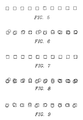
- a convenient way to think of the development of the image is in terms of an assembly of rows of pixel locations, as illustrated in Figure 5. In this Figure (as well as Figures 6-13), a row of pixel locations is indicated by a row of horizontal squares, each square being a pixel.
- the number of pixels is 118 per cm (300 per inch) or more, but a smaller number of widely spaced pixels are shown for illustrative purposes. Also, the pixels are normally placed immediately adjacent each other, but in the illustration of Figures 5-13 there is a spacing between pixels for clarity of illustration.
- Figure 6 illustrates the printing of a row of pixels of a single color (as in black printing) using the conventional practice.
- the nozzles 18 of Figure 2 passes along the row, it ejects droplets of colorant at the appropriate times based upon the content of the image. Not all of the droplets strike the exact center of the pixel, and some of the dots are therefore slightly displaced so that the pixel is not fully covered. A white unprinted area is therefore present in the image over that portion of the printed pixel which is not covered.
- the printed dots are shown as circles having diameters of about the side of the square. There therefore appears to be a large amount of unprinted space between pixels. In reality, the pixels are immediately adjacent and the dots are slightly larger than the pixels, so that full coverage is achieved. The present approach to depicting spaced apart dots and pixels was chosen to permit clear illustration of the principles involved.
- FIG 8. One aspect of the present approach, most preferred for printing single color images such as black characters or black/grey images, is illustrated in Figure 8. Two dots are deposited on each pixel location, each droplet being ejected from a different nozzle. It is expected that each dot will be displaced somewhat from perfect coverage of the pixel, in the manner shown in Figure 6, but since two different nozzles are employed, the variations of coverage for the two dots are expected to vary in a statistical manner. As shown for the various pixels in the row of Figure 8, the result is better coverage of each pixel location than in the prior approach. There are fewer white areas within the pixels using the present approach. This improvement to the image quality is present in new as well as old print heads that have been in operation for some time.
- the DDA (double dot always) embodiment of the present invention yields important benefits in both the initial quality of the image, and the quality after nozzle operation becomes impaired during the life of the print head.
- the two droplets that form each dot be deposited on successive passes of the print head 10, permitting the first deposited droplet to dry before the second droplet is deposited overlying the first droplet.
- the successive passes can be performed with two different print heads, but a preferred approach is to use a single print head, such as that illustrated in Figures 1-3, with the nozzles divided into two groups, as illustrated in Figure 2.
- the print head first passes across the face of the printing medium in the direction 52, with droplets being deposited onto the printing medium in the required pattern by a first group of nozzles 54 (the 12 nozzles on the left of Figure 2). After the first pass is complete, the printing medium is moved in an amount and direction indicated by the arrow 74, so that the strip of printing medium previously lying under the first group of nozzles 54 now lies under a second group of nozzles 56 (the 12 nozzles on the right of Figure 2).
- the print head then traverses across the printing medium in a second pass in the direction 52 with the second group of nozzles 56 depositing droplets of ink in exactly the same pattern during the second pass as did the first group of nozzles 54 in the first pass.
- the array of nozzles in the second group 56 is identical to that of the first group 54, and therefore the droplets deposited by the second group of nozzles 54 overlie the droplets deposited by the first group of nozzles 52.
- the output of the printer can be increased by printing the second group of droplets with the print head moving in the opposite direction to that of the arrow 52, so that both droplets for each dot are printed in a single traverse and return to the original position of the print head.
- the first group of nozzles 54 deposits the first set of droplets for the next printed swath of the pattern. That is, the all of the nozzles of the print head are available for operation during each pass. Control of the printing is accomplished using the printer buffer available in printers to control the prior approach. The print head operates in conjunction with the printer buffer. The locations to be printed in a pass are calculated by the known printing algorithm, which decomposes each swath of the image into a pattern of dots. The present approach determines the locations of the dots to be printed for the first swath, which are printed in the first pass by the first group 54 of nozzles.
- the locations from the print buffer printed by the first group of nozzles 54 in the first pass are then moved to the appropriate buffer locations to control the deposition of the droplets by the second group 56 of nozzles in the second pass, resulting in the previously described overprinting of each dot a second time during the second pass.
- a new swath of locations to be printed is loaded into the portion of the buffer controlling the first group 54 of nozzles and printed in the second pass, and these locations are printed while the second group 56 of nozzles are depositing droplets on the previously printed group of dots.
- color images are formed by providing four print heads (or dedicated sections of one or two print heads), each one depositing a different primary color.
- Secondary colors are formed by depositing droplets of two primary colors over each other.
- the usual primary colors provided in the printer are yellow, black, cyan, and magenta. Red is printed as the superposition of yellow and magenta droplets, green is printed as the superposition of yellow and cyan droplets, and blue is printed as the superposition of magenta and cyan droplets.
- One approach to improving image quality according to the invention is printing two droplets of each color, from two different nozzles, for each of the two primary colors required for a pixel location of a secondary color. Two droplets of the same color, from different nozzles, are printed for each primary color. This approach yields improved coverage of the pixel locations for the reasons discussed earlier. It may also result in distortions in color due to multiple superposition of dots, and can also cause cockle of the paper and running of the droplets because the printing medium cannot absorb the liquid deposited from four droplets at each secondary pixel location. For these reasons, this approach is not preferred.
- each secondary color is formed by two droplets even under conventional approaches, but these two droplets are of different colors. It is assumed for simplicity that the same secondary colors are formed in each case, but that one of the two pixels labelled as primary colors is one of the primary colors used to form the secondary color and that the other primary colored pixel is of the other primary color used to form the secondary color. Thus, in the prior approach illustrated in Figure 10, two dots are present on each secondary color pixel, and one dot is present on each primary color pixel.
- each pixel is labelled in two ways. First, it is labelled as being a secondary color S or a primary color P, because the images cannot be printed in color. Second, each pixel is labelled as to whether it is the correct color "OK”, a distorted color "D", or an uncolored pixel "X". These latter indications become significant in assessing images degraded due to inoperative or partially operative nozzles.
- Figure 10 illustrates the formation of primary and secondary colors under the prior approach.
- One primary color dot is present on each P pixel, and two primary color dots are present on each S pixel. If one of the nozzles producing the primary colors becomes inoperable, the result is shown in Figure 11. All of the S pixels have a distorted color, because only one of the primary colors is deposited thereupon.
- One of the P pixels is acceptable, and the other has no dot printed on it and is uncolored. This image is highly degraded, because only one of the original pixels has the correct color, most of the other pixels have distorted colors, and one of the pixels has no color at all.
- the first pixel in a row, the S pixel 100 is printed by two dots of different colors C1 and C2, the color C1 being ejected by nozzle N1(C1) and the other color C2 being ejected by nozzle N1(C2).
- the second pixel in the row, the S pixel 102 is printed by two dots of different colors C1 and C2 (the same colors as printed onto pixel 100), but from different nozzles N2(C1) and N2(C2), respectively.
- the third S pixel 104 is printed by the same two nozzles that printed the first pixel 100, N1(C1) and N1(C2).
- the fourth X pixel 106 is printed by the same two nozzles that printed the second pixel 102, N2(C1) and N2(C2).
- the fifth pixel in the illustrated example is a primary color pixel, here assumed to be the primary color C1. It is printed with two dots produced by the two nozzles that deposit the C1 color, N1(C1) and N2(C1).
- the pattern of alternating nozzles printing the secondary color pixels then continues.
- the other primary color pixel 110 which is assumed to be the C2 color, is printed using the two nozzles that print the C2 color, N1(C2) and N2(C2).
- the primary color pixels 108 and 110 have two dots of the same color on the pixel, rather than one dot as in the prior approach.
- Figure 13 illustrates the resulting color arrangement in the event that one of the nozzles fails, here assumed to be N1(C1).
- the color of pixel 100 is distorted, that of pixel 102 is correct, that of pixel 104 is distorted, and that of pixel 106 is correct.
- the color of the primary color pixel 108 is correct, even though one of the nozzles depositing on that pixel failed.
- the succeeding secondary color pixels have the repeating pattern of correct and distorted color.
- the primary pixel 110 has the correct color, as neither of the nozzles contributing to its color failed.
- Figure 13 The appearance of the pixel row using the present approach, Figure 13, may be contrasted with that using the prior approach, Figure 11.
- Figure 13 all of the primary pixels are printed and have the correct color.
- Half of the secondary pixels have the correct color, and have have a distorted color. None of the pixels are unprinted.
- the appearance of the row is therefore much less degraded by the failure of a single nozzle than is the appearance of the row in Figure 11, also degraded by failure of a single nozzle.
- Figures 10-13 are, of course, exemplary of a pixel row, and their specific appearance reflects the assumptions discussed above.
- the use of multiple nozzles for each color of a row is not restricted to two nozzles, but is applicable for three or more nozzles ejecting colorant of the same color, for each pixel row.
- the computational procedures are more complex, and the printing time for each page of the printing medium is slower.
- the use of two nozzles for each color of the row is therefore preferred.
- Printing of the row of pixels with primary and secondary colors is by the approach discussed earlier for single color printing, except that multiple print heads of a single color each, or multiple clusters of nozzles of a single color in a single print head, are used.
Landscapes
- Engineering & Computer Science (AREA)
- Quality & Reliability (AREA)
- Ink Jet (AREA)
- Particle Formation And Scattering Control In Inkjet Printers (AREA)
Applications Claiming Priority (2)
| Application Number | Priority Date | Filing Date | Title |
|---|---|---|---|
| US290543 | 1988-12-27 | ||
| US07290543 US4963882B1 (en) | 1988-12-27 | 1988-12-27 | Printing of pixel locations by an ink jet printer using multiple nozzles for each pixel or pixel row |
Publications (3)
| Publication Number | Publication Date |
|---|---|
| EP0376596A2 true EP0376596A2 (fr) | 1990-07-04 |
| EP0376596A3 EP0376596A3 (fr) | 1991-04-03 |
| EP0376596B1 EP0376596B1 (fr) | 1994-06-01 |
Family
ID=23116485
Family Applications (1)
| Application Number | Title | Priority Date | Filing Date |
|---|---|---|---|
| EP89313320A Expired - Lifetime EP0376596B1 (fr) | 1988-12-27 | 1989-12-20 | Dispositif d'impression par jet d'encre de positions d'éléments d'image utilisant des buses multiples pour chaque élément d'image ou rangée d'éléments d'image |
Country Status (6)
| Country | Link |
|---|---|
| US (1) | US4963882B1 (fr) |
| EP (1) | EP0376596B1 (fr) |
| JP (1) | JP3163089B2 (fr) |
| CA (1) | CA1321510C (fr) |
| DE (1) | DE68915726T2 (fr) |
| HK (1) | HK11995A (fr) |
Cited By (20)
| Publication number | Priority date | Publication date | Assignee | Title |
|---|---|---|---|---|
| GB2242868A (en) * | 1990-02-26 | 1991-10-16 | Canon Kk | Ink jet multi-tone printing with superposed dots. |
| EP0471488A2 (fr) * | 1990-08-14 | 1992-02-19 | Tektronix Inc. | Impression entrelacée utilisant des séries d'impression espacée |
| EP0516366A2 (fr) * | 1991-05-27 | 1992-12-02 | Canon Kabushiki Kaisha | Dispositif d'enregistrement à jet d'encre et méthode capable d'augmenter la densité |
| EP0517543A2 (fr) | 1991-06-07 | 1992-12-09 | Canon Kabushiki Kaisha | Méthode d'enregistrement par jet d'encre |
| EP0517520A2 (fr) * | 1991-06-07 | 1992-12-09 | Canon Kabushiki Kaisha | Méthode et dispositif d'enregistrement par jet d'encre |
| EP0517519A2 (fr) * | 1991-06-06 | 1992-12-09 | Canon Kabushiki Kaisha | Méthode et dispositif d'enregistrement |
| EP0517521A3 (en) * | 1991-06-05 | 1992-12-30 | Canon Kabushiki Kaisha | Tone recording method using ink jet recording head |
| EP0618076A2 (fr) * | 1993-03-31 | 1994-10-05 | Canon Kabushiki Kaisha | Méthode et appareil pour l'impression par jet d'encre |
| US5430469A (en) * | 1991-06-05 | 1995-07-04 | Canon Kabushiki Kaisha | Tone recording method using ink recording head |
| WO1996032263A1 (fr) * | 1995-04-12 | 1996-10-17 | Eastman Kodak Company | Doublement des buses pour obtenir une tolerance aux defauts dans les tetes d'impression integrees |
| EP0790509A2 (fr) * | 1996-02-16 | 1997-08-20 | Canon Kabushiki Kaisha | Méthode et appareil pour la fabrication d'un filtre coloré, filtre coloré, dispositif d'affichage et appareil l'utilisant |
| EP0718105B1 (fr) * | 1994-12-22 | 1999-08-11 | Hewlett-Packard Company | Motif de masque pour imprimante à jet d'encre |
| NL1008760C2 (nl) | 1998-03-31 | 1999-10-01 | Stork Digital Imaging Bv | Drukinrichting en werkwijze voor het patroonsgewijs op een substraat drukken van beeldpunten uit een of meer inktdruppels. |
| EP0881082A3 (fr) * | 1997-05-29 | 2000-05-03 | Xerox Corporation | Dispositif et procédé de formation d'images avec réduction des défauts d'impression |
| SG85086A1 (en) * | 1994-03-31 | 2001-12-19 | Canon Kk | Color filter manufacturing method and apparatus, color filter, liquid crystal display device, and apparatus having liquid crystal display apparatus |
| US6354689B1 (en) * | 1998-12-22 | 2002-03-12 | Eastman Kodak Company | Method of compensating for malperforming nozzles in a multitone inkjet printer |
| US6406114B1 (en) | 1991-06-05 | 2002-06-18 | Canon Kabushiki Kaisha | Tonal product recorded by ink and having a plurality of pixels with plural tonal levels |
| US6491372B1 (en) | 1992-10-16 | 2002-12-10 | Canon Kabushiki Kaisha | Ink jet recording method and ink jet recording apparatus |
| CN104275935A (zh) * | 2013-07-12 | 2015-01-14 | 精工爱普生株式会社 | 点记录装置和点记录方法 |
| WO2016045272A1 (fr) * | 2014-09-25 | 2016-03-31 | 京东方科技集团股份有限公司 | Dispositif électroluminescent et son procédé de fabrication, substrat d'affichage et appareil d'affichage |
Families Citing this family (126)
| Publication number | Priority date | Publication date | Assignee | Title |
|---|---|---|---|---|
| US5583550A (en) * | 1989-09-29 | 1996-12-10 | Hewlett-Packard Company | Ink drop placement for improved imaging |
| JPH03297654A (ja) * | 1990-04-16 | 1991-12-27 | Ricoh Co Ltd | インク飛翔記録方法 |
| US5815173A (en) * | 1991-01-30 | 1998-09-29 | Canon Kabushiki Kaisha | Nozzle structures for bubblejet print devices |
| DE69213101T2 (de) * | 1991-05-31 | 1997-01-30 | Canon Kk | Farbstrahlaufzeichnungsverfahren und Vorrichtung |
| JP2986124B2 (ja) * | 1991-06-14 | 1999-12-06 | キヤノン株式会社 | インクジェット記録装置 |
| US6007174A (en) * | 1991-07-30 | 1999-12-28 | Canon Kabushiki Kaisha | Ink jet recording apparatus and method |
| ES2110473T3 (es) * | 1991-07-30 | 1998-02-16 | Canon Kk | Aparato y metodo para la impresion por chorros de tinta. |
| JPH0531920A (ja) * | 1991-08-01 | 1993-02-09 | Canon Inc | インクジエツト記録装置 |
| DE69233216T2 (de) * | 1991-08-02 | 2004-07-08 | Canon K.K. | Tintenstrahlaufzeichnungsverfahren |
| US5235352A (en) * | 1991-08-16 | 1993-08-10 | Compaq Computer Corporation | High density ink jet printhead |
| US5402162A (en) * | 1991-08-16 | 1995-03-28 | Compaq Computer Corporation | Integrated multi-color ink jet printhead |
| US5406319A (en) * | 1991-08-16 | 1995-04-11 | Compaq Computer Corporation | Enhanced U type ink jet printheads |
| US5461403A (en) * | 1991-08-16 | 1995-10-24 | Compaq Computer Corporation | Droplet volume modulation techniques for ink jet printheads |
| CA2075786A1 (fr) * | 1991-08-16 | 1993-02-17 | John R. Pies | Methode de fabrication d'une tete a imprimer a jet d'encre sous pression |
| US5521618A (en) * | 1991-08-16 | 1996-05-28 | Compaq Computer Corporation | Dual element switched digital drive system for an ink jet printhead |
| US5436648A (en) * | 1991-08-16 | 1995-07-25 | Compaq Computer Corporation | Switched digital drive system for an ink jet printhead |
| US5400064A (en) * | 1991-08-16 | 1995-03-21 | Compaq Computer Corporation | High density ink jet printhead with double-U channel actuator |
| US5208605A (en) * | 1991-10-03 | 1993-05-04 | Xerox Corporation | Multi-resolution roofshooter printheads |
| US5247315A (en) * | 1992-02-06 | 1993-09-21 | Gerber Scientific Products, Inc. | Method of printing a graphic having uniform ink density on an emulsion coated printing screen |
| JP3100790B2 (ja) * | 1992-02-26 | 2000-10-23 | キヤノン株式会社 | 画像記録装置及び方法 |
| JP3005136B2 (ja) | 1992-04-27 | 2000-01-31 | キヤノン株式会社 | プリント装置およびプリント方法 |
| US5276467A (en) * | 1992-05-04 | 1994-01-04 | Hewlett-Packard Company | Alignment system for multiple color pen cartridges |
| US6106102A (en) * | 1992-05-01 | 2000-08-22 | Hewlett-Packard Company | Odd number of passes, odd number of advances, and separated-diagonal-line masking, in liquid-ink printers |
| US5485180A (en) * | 1992-08-05 | 1996-01-16 | Hewlett-Packard Company | Inking for color-inkjet printers, using non-integral drop averages, media varying inking, or more than two drops per pixel |
| EP0595657B1 (fr) * | 1992-10-30 | 2001-04-04 | Canon Kabushiki Kaisha | Système et appareil pour l'enregistrement par jet d'encre |
| US5555006A (en) * | 1993-04-30 | 1996-09-10 | Hewlett-Packard Company | Inkjet printing: mask-rotation-only at page extremes; multipass modes for quality and throughput on plastic media |
| US5426455A (en) * | 1993-05-10 | 1995-06-20 | Compaq Computer Corporation | Three element switched digital drive system for an ink jet printhead |
| US5557304A (en) * | 1993-05-10 | 1996-09-17 | Compaq Computer Corporation | Spot size modulatable ink jet printhead |
| US5444467A (en) * | 1993-05-10 | 1995-08-22 | Compaq Computer Corporation | Differential drive system for an ink jet printhead |
| US5485183A (en) * | 1993-06-30 | 1996-01-16 | Dataproducts Corporation | Interlaced dot-on-dot printing |
| IT1261240B (it) * | 1993-08-19 | 1996-05-09 | Olivetti Canon Ind Spa | Metodo di stampa a punti e relativa testina di stampa a getto d'inchiostro. |
| US5883644A (en) * | 1993-10-29 | 1999-03-16 | Hewlett-Packard Company | Resolution-dependent and color-dependent print masking |
| US5885661A (en) * | 1993-11-24 | 1999-03-23 | Semiconductor Systems, Inc. | Droplet jet method for coating flat substrates with resist or similar materials |
| US5790152A (en) * | 1994-04-12 | 1998-08-04 | Xerox Corporation | Thermal ink-jet printhead for creating spots of selectable sizes |
| DE69511470T2 (de) | 1994-06-15 | 1999-12-16 | Compaq Computer Corp., Houston | Verfahren und Druckkopf zur Erzeugung von Gradiententondarstellungen |
| US5640183A (en) * | 1994-07-20 | 1997-06-17 | Hewlett-Packard Company | Redundant nozzle dot matrix printheads and method of use |
| JP3308717B2 (ja) * | 1994-07-21 | 2002-07-29 | キヤノン株式会社 | 記録装置及び記録方法 |
| US5666143A (en) * | 1994-07-29 | 1997-09-09 | Hewlett-Packard Company | Inkjet printhead with tuned firing chambers and multiple inlets |
| US5912685A (en) * | 1994-07-29 | 1999-06-15 | Hewlett-Packard Company | Reduced crosstalk inkjet printer printhead |
| US5625397A (en) * | 1994-11-23 | 1997-04-29 | Iris Graphics, Inc. | Dot on dot ink jet printing using inks of differing densities |
| US5581284A (en) * | 1994-11-25 | 1996-12-03 | Xerox Corporation | Method of extending the life of a printbar of a color ink jet printer |
| US5734399A (en) * | 1995-07-11 | 1998-03-31 | Hewlett-Packard Company | Particle tolerant inkjet printhead architecture |
| JP3111024B2 (ja) * | 1995-07-19 | 2000-11-20 | キヤノン株式会社 | カラーフィルタの製造装置及び製造方法及び表示装置の製造方法及び表示装置を備えた装置の製造方法 |
| US5745131A (en) * | 1995-08-03 | 1998-04-28 | Xerox Corporation | Gray scale ink jet printer |
| JPH09226127A (ja) * | 1995-12-18 | 1997-09-02 | Canon Inc | 記録装置及びその方法、該装置を備えたファクシミリ装置 |
| JP3359211B2 (ja) | 1995-12-28 | 2002-12-24 | キヤノン株式会社 | 記録方法および記録装置 |
| JPH09207324A (ja) | 1996-02-05 | 1997-08-12 | Canon Inc | 記録方法及びその装置及び記録システム |
| JPH09262970A (ja) * | 1996-03-28 | 1997-10-07 | Canon Inc | インクジェット記録装置 |
| US5880752A (en) * | 1996-05-09 | 1999-03-09 | Hewlett-Packard Company | Print system for ink-jet pens |
| US6502912B1 (en) | 1996-09-23 | 2003-01-07 | Pitney Bowes Inc. | Method of printing postage indicia using ink jet technology |
| US5912682A (en) * | 1996-09-23 | 1999-06-15 | Pitney Bowes Inc. | Method of printing using inks having different characteristics |
| US6259463B1 (en) | 1997-10-30 | 2001-07-10 | Hewlett-Packard Company | Multi-drop merge on media printing system |
| US6193347B1 (en) | 1997-02-06 | 2001-02-27 | Hewlett-Packard Company | Hybrid multi-drop/multi-pass printing system |
| US6367912B1 (en) * | 1997-02-24 | 2002-04-09 | Oki Data Corporation | Ink jet recording apparatus |
| US6067405A (en) | 1997-03-04 | 2000-05-23 | Hewlett-Packard Company | Multipass color printmasks based on location rules to minimize hue shift, banding and coalescence |
| US6019454A (en) | 1997-03-04 | 2000-02-01 | Hewlett-Packard Company | Multipass inkjet printmodes with randomized dot placement, to minimize patterning and liquid loading |
| US6250739B1 (en) | 1997-03-04 | 2001-06-26 | Hewlett-Packard Company | Bidirectional color printmodes with semistaggered swaths to minimize hue shift and other artifacts |
| US6283572B1 (en) | 1997-03-04 | 2001-09-04 | Hewlett-Packard Company | Dynamic multi-pass print mode corrections to compensate for malfunctioning inkjet nozzles |
| US6367908B1 (en) | 1997-03-04 | 2002-04-09 | Hewlett-Packard Company | High-resolution inkjet printing using color drop placement on every pixel row during a single pass |
| JP3332854B2 (ja) * | 1997-06-17 | 2002-10-07 | キヤノン株式会社 | カラーフィルタの製造方法 |
| US6007188A (en) | 1997-07-31 | 1999-12-28 | Hewlett-Packard Company | Particle tolerant printhead |
| EP0999935B1 (fr) * | 1997-08-01 | 2003-11-05 | Encad, Inc. | Imprimante a jet d'encre, et procede et systeme permettant de compenser le non-fonctionnement de certains elements d'impression |
| US6135655A (en) * | 1997-10-14 | 2000-10-24 | Hewlett-Packard Company | Multipixel dots in monochrome drop-on-demand printing |
| US6157461A (en) * | 1997-10-27 | 2000-12-05 | Hewlett-Packard Company | Method of generating randomized masks to improve image quality on a printing medium |
| US6193345B1 (en) | 1997-10-30 | 2001-02-27 | Hewlett-Packard Company | Apparatus for generating high frequency ink ejection and ink chamber refill |
| US6234613B1 (en) | 1997-10-30 | 2001-05-22 | Hewlett-Packard Company | Apparatus for generating small volume, high velocity ink droplets in an inkjet printer |
| JPH11216856A (ja) * | 1997-11-14 | 1999-08-10 | Canon Inc | 記録装置および方法 |
| US6209203B1 (en) | 1998-01-08 | 2001-04-03 | Lexmark International, Inc. | Method for making nozzle array for printhead |
| US6626527B1 (en) * | 1998-03-12 | 2003-09-30 | Creo Americas, Inc. | Interleaved printing |
| JP4250264B2 (ja) * | 1998-07-22 | 2009-04-08 | キヤノン株式会社 | 記録装置及びその制御方法、コンピュータ可読メモリ |
| US6273549B1 (en) * | 1998-08-13 | 2001-08-14 | Hewlett-Packard Company | Multiple pass color shift correction technique for an inkjet printer |
| NL1012376C2 (nl) | 1999-06-17 | 2000-12-19 | Ocu Technologies B V | Werkwijze voor het bedrukken van een substraat en een drukinrichting geschikt om deze werkwijze toe te passen. |
| NL1012816C2 (nl) * | 1999-08-12 | 2001-02-13 | Ocu Technologies B V | Werkwijze voor het bedrukken van een substraat en een drukinrichting geschikt om deze werkwijze toe te passen. |
| US6278469B1 (en) * | 1999-09-20 | 2001-08-21 | Hewlett-Packard Company | Customizing printmasks for printhead nozzle aberrations |
| US6604806B1 (en) | 1999-10-20 | 2003-08-12 | Canon Kabushiki Kaisha | High resolution printing |
| JP2001162784A (ja) * | 1999-12-13 | 2001-06-19 | Canon Inc | インクジェット記録装置および記録方法 |
| US6336701B1 (en) | 1999-12-22 | 2002-01-08 | Hewlett-Packard Company | Ink-jet print pass microstepping |
| US6530645B2 (en) | 2000-04-03 | 2003-03-11 | Eastman Kodak Company | Print masks for high speed ink jet printing |
| AUPQ766300A0 (en) * | 2000-05-22 | 2000-06-15 | Canon Kabushiki Kaisha | Defective nozzle compensation |
| US6754551B1 (en) | 2000-06-29 | 2004-06-22 | Printar Ltd. | Jet print apparatus and method for printed circuit board manufacturing |
| CN100344452C (zh) * | 2000-06-30 | 2007-10-24 | 西尔弗布鲁克研究有限公司 | 修正要通过打印设备进行数码打印的图像的方法 |
| US6890760B1 (en) * | 2000-07-31 | 2005-05-10 | Agilent Technologies, Inc. | Array fabrication |
| US6995863B1 (en) * | 2000-08-19 | 2006-02-07 | Hewlett-Packard Development Company, L.P. | Discretionary dotting for artifact control in incremental printing |
| US6367913B1 (en) * | 2000-10-31 | 2002-04-09 | Hewlett-Packard Company | System and method for improving the lightfastness of color printouts |
| US6523920B2 (en) * | 2001-02-01 | 2003-02-25 | Hewlett-Packard Company | Combination ink jet pen and optical scanner head and methods of improving print quality |
| US7046389B2 (en) * | 2001-04-04 | 2006-05-16 | Hewlett-Packard Development Company, L.P. | Variable density under/overprinting maps for improving print quality |
| JP4027204B2 (ja) * | 2001-11-06 | 2007-12-26 | キヤノン株式会社 | 記録装置及び記録方法並びにデータ処理装置 |
| JP3768890B2 (ja) * | 2002-01-31 | 2006-04-19 | キヤノン株式会社 | 記録装置及び電圧制御方法 |
| DE60210208T2 (de) | 2002-03-15 | 2006-12-28 | Agfa-Gevaert | Druckverfahren und -vorrichtung zum Austauschen defekter Druckelemente |
| US6874862B2 (en) * | 2002-04-26 | 2005-04-05 | Hewlett-Packard Development Company, L.P. | Inkjet printing device with multiple nozzles positioned to print at each target location on a print medium |
| US7188919B2 (en) * | 2002-07-08 | 2007-03-13 | Canon Kabushiki Kaisha | Liquid discharge method and apparatus using individually controllable nozzles |
| US7111755B2 (en) * | 2002-07-08 | 2006-09-26 | Canon Kabushiki Kaisha | Liquid discharge method and apparatus and display device panel manufacturing method and apparatus |
| US6779861B2 (en) | 2002-12-16 | 2004-08-24 | Xerox Corporation | Enhanced dot resolution for inkjet printing |
| US6695435B1 (en) | 2003-05-30 | 2004-02-24 | Xerox Corporation | Selective replacement for artifact reduction |
| US20050024402A1 (en) * | 2003-07-31 | 2005-02-03 | Quintana Jason M. | Transfer of data from a controller to an output device |
| EP1525988A1 (fr) * | 2003-10-24 | 2005-04-27 | Hewlett-Packard Development Company, L.P. | Méthode et dispositif pour commander une imprimante |
| US7093918B2 (en) | 2004-04-16 | 2006-08-22 | Hewlett-Packard Development Company, L.P. | Double dotting for grain equalization |
| US20050248631A1 (en) * | 2004-05-10 | 2005-11-10 | Pinard Adam I | Stitched printing system |
| US7658460B2 (en) * | 2004-08-06 | 2010-02-09 | Canon Finetech Inc. | Printing apparatus, method, and program comprising a plurality of printer units using synchronized, divided print data |
| JP2006076266A (ja) * | 2004-09-13 | 2006-03-23 | Fuji Xerox Co Ltd | インクジェットの噴射状態検出方法、及びインクジェット記録装置 |
| TWI253403B (en) * | 2005-03-17 | 2006-04-21 | Sunplus Technology Co Ltd | Method and apparatus for controlling printing speed and quality |
| US7338144B2 (en) * | 2005-09-29 | 2008-03-04 | Xerox Corporation | Ink jet printer having print head with partial nozzle redundancy |
| US7758173B2 (en) * | 2005-12-23 | 2010-07-20 | Xerox Corporation | Collapsible packaging system |
| US7577384B2 (en) * | 2005-12-23 | 2009-08-18 | Xerox Corporation | Collapsible packaging system |
| US8351062B2 (en) * | 2007-02-26 | 2013-01-08 | Marvell World Trade Ltd. | Bit selection from print image in memory of handheld image translation device |
| DE602007008908D1 (de) * | 2007-10-31 | 2010-10-14 | Xennia Holland Bv | Druckanordnung und Verfahren zur Ablagerung einer Substanz |
| US8042899B2 (en) * | 2008-03-17 | 2011-10-25 | Xerox Corporation | System and method for compensating for weak, intermittent, or missing inkjets in a printhead assembly |
| US8235489B2 (en) * | 2008-05-22 | 2012-08-07 | Fujifilm Dimatix, Inc. | Ink jetting |
| GB0907362D0 (en) | 2009-04-29 | 2009-06-10 | Ten Cate Itex B V | Print carriage |
| JP2011000826A (ja) * | 2009-06-19 | 2011-01-06 | Canon Inc | 記録マスク符号化方法および記録方法および記録装置 |
| US8123319B2 (en) * | 2009-07-09 | 2012-02-28 | Fujifilm Corporation | High speed high resolution fluid ejection |
| GB2483473A (en) | 2010-09-08 | 2012-03-14 | Ten Cate Advanced Textiles Bv | Print head module having staggered overlapping first and second printheads |
| US8419160B2 (en) | 2011-06-08 | 2013-04-16 | Xerox Corporation | Method and system for operating a printhead to compensate for failed inkjets |
| US8985723B2 (en) | 2012-04-20 | 2015-03-24 | Xerox Corporation | System and method of compensating for defective inkjets |
| US8714692B1 (en) | 2012-12-04 | 2014-05-06 | Xerox Corporation | System and method of compensating for defective inkjets with context dependent image data |
| US9700908B2 (en) | 2012-12-27 | 2017-07-11 | Kateeva, Inc. | Techniques for arrayed printing of a permanent layer with improved speed and accuracy |
| US11673155B2 (en) | 2012-12-27 | 2023-06-13 | Kateeva, Inc. | Techniques for arrayed printing of a permanent layer with improved speed and accuracy |
| US9352561B2 (en) | 2012-12-27 | 2016-05-31 | Kateeva, Inc. | Techniques for print ink droplet measurement and control to deposit fluids within precise tolerances |
| US8995022B1 (en) | 2013-12-12 | 2015-03-31 | Kateeva, Inc. | Ink-based layer fabrication using halftoning to control thickness |
| US9832428B2 (en) | 2012-12-27 | 2017-11-28 | Kateeva, Inc. | Fast measurement of droplet parameters in industrial printing system |
| US11141752B2 (en) | 2012-12-27 | 2021-10-12 | Kateeva, Inc. | Techniques for arrayed printing of a permanent layer with improved speed and accuracy |
| KR20190123811A (ko) | 2012-12-27 | 2019-11-01 | 카티바, 인크. | 정밀 공차 내로 유체를 증착하기 위한 인쇄 잉크 부피 제어를 위한 기법 |
| US8824014B1 (en) | 2013-02-11 | 2014-09-02 | Xerox Corporation | System and method for adjustment of coverage parameters for different colors in image data |
| JP6148584B2 (ja) * | 2013-09-18 | 2017-06-14 | 理想科学工業株式会社 | インクジェット印刷装置 |
| US11472195B2 (en) | 2018-03-14 | 2022-10-18 | Hewlett-Packard Development Company, L.P. | Redundancy print modes |
| JP7380040B2 (ja) * | 2019-10-03 | 2023-11-15 | 富士フイルムビジネスイノベーション株式会社 | インクジェット記録装置 |
Citations (5)
| Publication number | Priority date | Publication date | Assignee | Title |
|---|---|---|---|---|
| US4528576A (en) * | 1982-04-15 | 1985-07-09 | Canon Kabushiki Kaisha | Recording apparatus |
| JPS60253557A (ja) * | 1984-05-30 | 1985-12-14 | Fujitsu Ltd | ドツトプリンタ装置 |
| DE3620334A1 (de) * | 1985-06-21 | 1987-01-02 | Sharp Kk | Druckverfahren |
| WO1987003363A1 (fr) * | 1985-11-22 | 1987-06-04 | Hewlett-Packard Company | Imprimante a jet d'encre multitonalite et son procede de fonctionnement |
| GB2198391A (en) * | 1986-11-21 | 1988-06-15 | Brother Ind Ltd | Dot-matrix type printing heat control system |
Family Cites Families (10)
| Publication number | Priority date | Publication date | Assignee | Title |
|---|---|---|---|---|
| JPS54113217A (en) * | 1978-02-23 | 1979-09-04 | Sharp Corp | Ink jet recording device |
| JPS58147383A (ja) * | 1982-02-26 | 1983-09-02 | Hitachi Ltd | 感熱ヘツド記録装置 |
| JPS58179656A (ja) * | 1982-04-16 | 1983-10-20 | Canon Inc | 画像記録装置 |
| JPS58211458A (ja) * | 1982-06-01 | 1983-12-08 | Canon Inc | カラ−インクジエツト記録装置 |
| US4672432A (en) * | 1983-04-28 | 1987-06-09 | Canon Kabushiki Kaisha | Method for recording a color image using dots of colorants of different densities |
| US4631543A (en) * | 1983-09-28 | 1986-12-23 | Sanders Associates, Inc. | Method and apparatus for reducing the effects of impulse noise in Loran-C receivers |
| JPS60104333A (ja) * | 1983-11-10 | 1985-06-08 | Canon Inc | 液体噴射装置 |
| JPS60151061A (ja) * | 1984-01-20 | 1985-08-08 | Nec Corp | インクジエツト記録方式 |
| JPS60262663A (ja) * | 1984-06-12 | 1985-12-26 | Nec Corp | インクジエツト記録装置 |
| US4748453A (en) * | 1987-07-21 | 1988-05-31 | Xerox Corporation | Spot deposition for liquid ink printing |
-
1988
- 1988-12-27 US US07290543 patent/US4963882B1/en not_active Expired - Lifetime
-
1989
- 1989-07-13 CA CA000605620A patent/CA1321510C/fr not_active Expired - Fee Related
- 1989-12-20 DE DE68915726T patent/DE68915726T2/de not_active Expired - Lifetime
- 1989-12-20 EP EP89313320A patent/EP0376596B1/fr not_active Expired - Lifetime
- 1989-12-27 JP JP34499289A patent/JP3163089B2/ja not_active Expired - Fee Related
-
1995
- 1995-01-26 HK HK11995A patent/HK11995A/xx not_active IP Right Cessation
Patent Citations (5)
| Publication number | Priority date | Publication date | Assignee | Title |
|---|---|---|---|---|
| US4528576A (en) * | 1982-04-15 | 1985-07-09 | Canon Kabushiki Kaisha | Recording apparatus |
| JPS60253557A (ja) * | 1984-05-30 | 1985-12-14 | Fujitsu Ltd | ドツトプリンタ装置 |
| DE3620334A1 (de) * | 1985-06-21 | 1987-01-02 | Sharp Kk | Druckverfahren |
| WO1987003363A1 (fr) * | 1985-11-22 | 1987-06-04 | Hewlett-Packard Company | Imprimante a jet d'encre multitonalite et son procede de fonctionnement |
| GB2198391A (en) * | 1986-11-21 | 1988-06-15 | Brother Ind Ltd | Dot-matrix type printing heat control system |
Non-Patent Citations (1)
| Title |
|---|
| PATENT ABSTRACTS OF JAPAN, vol. 10, no. 126 (M-477)[2183], 10th May 1986; & JP-A-60 253 557 (FUJITSU K.K.) 14-12-1985 * |
Cited By (42)
| Publication number | Priority date | Publication date | Assignee | Title |
|---|---|---|---|---|
| GB2242868A (en) * | 1990-02-26 | 1991-10-16 | Canon Kk | Ink jet multi-tone printing with superposed dots. |
| US5726691A (en) * | 1990-02-26 | 1998-03-10 | Canon Kabushiki Kaisha | Recording apparatus and method for recording droplets in registry |
| GB2242868B (en) * | 1990-02-26 | 1994-10-26 | Canon Kk | Recording apparatus for performing recording using ink-jet recording head and recording method |
| EP0471488A2 (fr) * | 1990-08-14 | 1992-02-19 | Tektronix Inc. | Impression entrelacée utilisant des séries d'impression espacée |
| EP0471488A3 (en) * | 1990-08-14 | 1992-10-28 | Tektronix, Inc. | Interlaced printing using spaced print arrays |
| EP0516366A2 (fr) * | 1991-05-27 | 1992-12-02 | Canon Kabushiki Kaisha | Dispositif d'enregistrement à jet d'encre et méthode capable d'augmenter la densité |
| US6540326B2 (en) | 1991-05-27 | 2003-04-01 | Canon Kabushiki Kaisha | Ink jet recording apparatus and method capable of increasing density |
| EP0516366A3 (en) * | 1991-05-27 | 1993-05-12 | Canon Kabushiki Kaisha | Ink jet recording apparatus and method capable of increasing density |
| AU690964B2 (en) * | 1991-06-05 | 1998-05-07 | Canon Kabushiki Kaisha | Tone recording method using ink jet recording head |
| EP0517521A3 (en) * | 1991-06-05 | 1992-12-30 | Canon Kabushiki Kaisha | Tone recording method using ink jet recording head |
| US5430469A (en) * | 1991-06-05 | 1995-07-04 | Canon Kabushiki Kaisha | Tone recording method using ink recording head |
| US5777640A (en) * | 1991-06-05 | 1998-07-07 | Canon Kabushiki Kaisha | Liquid jet recording method using plural scanning nozzles and including first main scan, sub-scan, and second main-scan steps for recording pixels in tone |
| US6406114B1 (en) | 1991-06-05 | 2002-06-18 | Canon Kabushiki Kaisha | Tonal product recorded by ink and having a plurality of pixels with plural tonal levels |
| US5844582A (en) * | 1991-06-05 | 1998-12-01 | Canon Kabushiki Kaisha | Liquid jet recording apparatus having specific relationship among number of nozzles, pitch of nozzles, movement distance maximum number of ink droplets per pixel and scan, and number of tone levels |
| US6260939B1 (en) * | 1991-06-05 | 2001-07-17 | Canon Kabushiki Kaisha | Tone recording method using ink jet recording head that records pixels using a plurality of liquid droplets |
| US6923522B2 (en) | 1991-06-06 | 2005-08-02 | Canon Kabushiki Kaisha | Recording apparatus and recording method |
| EP0517519A3 (en) * | 1991-06-06 | 1992-12-30 | Canon Kabushiki Kaisha | Recording apparatus and recording method |
| US6513906B1 (en) | 1991-06-06 | 2003-02-04 | Canon Kabushiki Kaisha | Recording apparatus and recording method |
| EP0517519A2 (fr) * | 1991-06-06 | 1992-12-09 | Canon Kabushiki Kaisha | Méthode et dispositif d'enregistrement |
| EP0517520A3 (en) * | 1991-06-07 | 1992-12-30 | Canon Kabushiki Kaisha | Ink-jet recording method and ink-jet recording apparatus |
| US5384587A (en) * | 1991-06-07 | 1995-01-24 | Canon Kabushiki Kaisha | Multi-drop ink-jet recording method with compensation for image density non-uniformities |
| EP0517543A2 (fr) | 1991-06-07 | 1992-12-09 | Canon Kabushiki Kaisha | Méthode d'enregistrement par jet d'encre |
| US5650803A (en) * | 1991-06-07 | 1997-07-22 | Canon Kabushiki Kaisha | Ink-jet recording method and ink-jet recording apparatus |
| EP0517520A2 (fr) * | 1991-06-07 | 1992-12-09 | Canon Kabushiki Kaisha | Méthode et dispositif d'enregistrement par jet d'encre |
| EP0517543A3 (fr) * | 1991-06-07 | 1992-12-23 | Canon Kabushiki Kaisha | Méthode d'enregistrement par jet d'encre |
| US6779872B2 (en) | 1992-10-16 | 2004-08-24 | Canon Kabushiki Kaisha | Ink jet recording method and ink jet recording apparatus |
| US6491372B1 (en) | 1992-10-16 | 2002-12-10 | Canon Kabushiki Kaisha | Ink jet recording method and ink jet recording apparatus |
| US5933162A (en) * | 1993-03-31 | 1999-08-03 | Canon Kabushiki Kaisha | Ink jet apparatus and ink jet method |
| EP0618076A3 (fr) * | 1993-03-31 | 1995-03-15 | Canon Kk | Méthode et appareil pour l'impression par jet d'encre. |
| EP0618076A2 (fr) * | 1993-03-31 | 1994-10-05 | Canon Kabushiki Kaisha | Méthode et appareil pour l'impression par jet d'encre |
| SG85086A1 (en) * | 1994-03-31 | 2001-12-19 | Canon Kk | Color filter manufacturing method and apparatus, color filter, liquid crystal display device, and apparatus having liquid crystal display apparatus |
| EP0718105B1 (fr) * | 1994-12-22 | 1999-08-11 | Hewlett-Packard Company | Motif de masque pour imprimante à jet d'encre |
| WO1996032263A1 (fr) * | 1995-04-12 | 1996-10-17 | Eastman Kodak Company | Doublement des buses pour obtenir une tolerance aux defauts dans les tetes d'impression integrees |
| US6500485B1 (en) * | 1996-02-16 | 2002-12-31 | Canon Kabushiki Kaisha | Color filter manufacturing method and apparatus, color filter, display device, and apparatus having display device |
| EP0790509A2 (fr) * | 1996-02-16 | 1997-08-20 | Canon Kabushiki Kaisha | Méthode et appareil pour la fabrication d'un filtre coloré, filtre coloré, dispositif d'affichage et appareil l'utilisant |
| EP0790509A3 (fr) * | 1996-02-16 | 1998-04-22 | Canon Kabushiki Kaisha | Méthode et appareil pour la fabrication d'un filtre coloré, filtre coloré, dispositif d'affichage et appareil l'utilisant |
| EP0881082A3 (fr) * | 1997-05-29 | 2000-05-03 | Xerox Corporation | Dispositif et procédé de formation d'images avec réduction des défauts d'impression |
| NL1008760C2 (nl) | 1998-03-31 | 1999-10-01 | Stork Digital Imaging Bv | Drukinrichting en werkwijze voor het patroonsgewijs op een substraat drukken van beeldpunten uit een of meer inktdruppels. |
| US6354689B1 (en) * | 1998-12-22 | 2002-03-12 | Eastman Kodak Company | Method of compensating for malperforming nozzles in a multitone inkjet printer |
| CN104275935A (zh) * | 2013-07-12 | 2015-01-14 | 精工爱普生株式会社 | 点记录装置和点记录方法 |
| CN104275935B (zh) * | 2013-07-12 | 2017-09-19 | 精工爱普生株式会社 | 点记录装置和点记录方法 |
| WO2016045272A1 (fr) * | 2014-09-25 | 2016-03-31 | 京东方科技集团股份有限公司 | Dispositif électroluminescent et son procédé de fabrication, substrat d'affichage et appareil d'affichage |
Also Published As
| Publication number | Publication date |
|---|---|
| DE68915726D1 (de) | 1994-07-07 |
| US4963882B1 (en) | 1996-10-29 |
| EP0376596B1 (fr) | 1994-06-01 |
| HK11995A (en) | 1995-02-03 |
| US4963882A (en) | 1990-10-16 |
| EP0376596A3 (fr) | 1991-04-03 |
| DE68915726T2 (de) | 1995-01-05 |
| JPH02231149A (ja) | 1990-09-13 |
| JP3163089B2 (ja) | 2001-05-08 |
| CA1321510C (fr) | 1993-08-24 |
Similar Documents
| Publication | Publication Date | Title |
|---|---|---|
| EP0376596B1 (fr) | Dispositif d'impression par jet d'encre de positions d'éléments d'image utilisant des buses multiples pour chaque élément d'image ou rangée d'éléments d'image | |
| US5640183A (en) | Redundant nozzle dot matrix printheads and method of use | |
| US6464316B1 (en) | Bi-directional printmode for improved edge quality | |
| US4940998A (en) | Carriage for ink jet printer | |
| US4593295A (en) | Ink jet image recording device with pitch-shifted recording elements | |
| US5654744A (en) | Simultaneously printing with different sections of printheads for improved print quality | |
| US4965593A (en) | Print quality of dot printers | |
| EP0665111B1 (fr) | Dispositif d'enregistrement à jet d'encre | |
| JP2003145732A (ja) | インク射出素子の補正方法 | |
| JPH10508808A (ja) | 高解像度マトリクスインクジェット装置 | |
| US6547354B1 (en) | Printing system that utilizes print masks with resolutions that are non-integral multiples of each other | |
| US20060262155A1 (en) | Liquid discharging apparatus and liquid discharging method | |
| US7959259B2 (en) | Inkjet printing apparatus and driving control method | |
| JPH06328734A (ja) | 印刷解像度の制御方法、インク・ジェット・プリンタ及びハイブリッド・ピクセル・グリッドの形成方法 | |
| JP5247006B2 (ja) | インクジェット記録装置およびインクジェット記録方法 | |
| JPH10250059A (ja) | インクジェット・プリンタ用の印刷ヘッドを製造する方法及び印刷方法 | |
| US6334659B1 (en) | Printing apparatus and printing method | |
| JPH1058714A (ja) | 記録媒体の上に画像を印刷する方法 | |
| JP4763886B2 (ja) | インクジェット記録方法およびインクジェット記録装置 | |
| EP0433556A2 (fr) | Appareil et procédé pour l'impression multicolore avec des jets d'encre | |
| US6273549B1 (en) | Multiple pass color shift correction technique for an inkjet printer | |
| CN109203696A (zh) | 一种喷墨打印装置及打印方法 | |
| JP3639703B2 (ja) | インクジェット記録装置およびインクジェット記録方法 | |
| JPH0776160A (ja) | ドット印刷方法及びドット印刷のためのインクジェット印字ヘッド | |
| US6688716B2 (en) | Ink jet recording apparatus and method |
Legal Events
| Date | Code | Title | Description |
|---|---|---|---|
| PUAI | Public reference made under article 153(3) epc to a published international application that has entered the european phase |
Free format text: ORIGINAL CODE: 0009012 |
|
| AK | Designated contracting states |
Kind code of ref document: A2 Designated state(s): DE FR GB IT |
|
| PUAL | Search report despatched |
Free format text: ORIGINAL CODE: 0009013 |
|
| AK | Designated contracting states |
Kind code of ref document: A3 Designated state(s): DE FR GB IT |
|
| 17P | Request for examination filed |
Effective date: 19910510 |
|
| 17Q | First examination report despatched |
Effective date: 19921203 |
|
| GRAA | (expected) grant |
Free format text: ORIGINAL CODE: 0009210 |
|
| AK | Designated contracting states |
Kind code of ref document: B1 Designated state(s): DE FR GB IT |
|
| REF | Corresponds to: |
Ref document number: 68915726 Country of ref document: DE Date of ref document: 19940707 |
|
| ET | Fr: translation filed | ||
| ITF | It: translation for a ep patent filed | ||
| PLBE | No opposition filed within time limit |
Free format text: ORIGINAL CODE: 0009261 |
|
| STAA | Information on the status of an ep patent application or granted ep patent |
Free format text: STATUS: NO OPPOSITION FILED WITHIN TIME LIMIT |
|
| 26N | No opposition filed | ||
| REG | Reference to a national code |
Ref country code: GB Ref legal event code: 732E |
|
| REG | Reference to a national code |
Ref country code: FR Ref legal event code: TP |
|
| REG | Reference to a national code |
Ref country code: GB Ref legal event code: IF02 |
|
| PGFP | Annual fee paid to national office [announced via postgrant information from national office to epo] |
Ref country code: IT Payment date: 20071229 Year of fee payment: 19 |
|
| PGFP | Annual fee paid to national office [announced via postgrant information from national office to epo] |
Ref country code: FR Payment date: 20071217 Year of fee payment: 19 |
|
| PGFP | Annual fee paid to national office [announced via postgrant information from national office to epo] |
Ref country code: DE Payment date: 20090202 Year of fee payment: 20 |
|
| PGFP | Annual fee paid to national office [announced via postgrant information from national office to epo] |
Ref country code: GB Payment date: 20081229 Year of fee payment: 20 |
|
| REG | Reference to a national code |
Ref country code: FR Ref legal event code: ST Effective date: 20090831 |
|
| REG | Reference to a national code |
Ref country code: GB Ref legal event code: PE20 Expiry date: 20091219 |
|
| PG25 | Lapsed in a contracting state [announced via postgrant information from national office to epo] |
Ref country code: GB Free format text: LAPSE BECAUSE OF EXPIRATION OF PROTECTION Effective date: 20091219 Ref country code: FR Free format text: LAPSE BECAUSE OF NON-PAYMENT OF DUE FEES Effective date: 20081231 |
|
| PG25 | Lapsed in a contracting state [announced via postgrant information from national office to epo] |
Ref country code: IT Free format text: LAPSE BECAUSE OF NON-PAYMENT OF DUE FEES Effective date: 20081220 |