EP0373653A2 - Vorrichtung zur Fahrzeugprüfung - Google Patents
Vorrichtung zur Fahrzeugprüfung Download PDFInfo
- Publication number
- EP0373653A2 EP0373653A2 EP89123157A EP89123157A EP0373653A2 EP 0373653 A2 EP0373653 A2 EP 0373653A2 EP 89123157 A EP89123157 A EP 89123157A EP 89123157 A EP89123157 A EP 89123157A EP 0373653 A2 EP0373653 A2 EP 0373653A2
- Authority
- EP
- European Patent Office
- Prior art keywords
- vehicle
- rollers
- pair
- moving platforms
- moving
- Prior art date
- Legal status (The legal status is an assumption and is not a legal conclusion. Google has not performed a legal analysis and makes no representation as to the accuracy of the status listed.)
- Granted
Links
Images


Classifications
-
- G—PHYSICS
- G01—MEASURING; TESTING
- G01M—TESTING STATIC OR DYNAMIC BALANCE OF MACHINES OR STRUCTURES; TESTING OF STRUCTURES OR APPARATUS, NOT OTHERWISE PROVIDED FOR
- G01M17/00—Testing of vehicles
- G01M17/007—Wheeled or endless-tracked vehicles
-
- G—PHYSICS
- G01—MEASURING; TESTING
- G01M—TESTING STATIC OR DYNAMIC BALANCE OF MACHINES OR STRUCTURES; TESTING OF STRUCTURES OR APPARATUS, NOT OTHERWISE PROVIDED FOR
- G01M17/00—Testing of vehicles
- G01M17/007—Wheeled or endless-tracked vehicles
- G01M17/0072—Wheeled or endless-tracked vehicles the wheels of the vehicle co-operating with rotatable rolls
- G01M17/0074—Details, e.g. roller construction, vehicle restraining devices
Definitions
- the present invention relates to a vehicle composite test apparatus wherein various test items of a vehicle are carried out with the tires placed or fixed on support bases being means to be detected, particularly to a vehicle composite test apparatus wherein a pair of support bases positioned on the front wheel side and a pair of support bases positioned on the rear wheel side can be moved toward or away from supporting points symmetrically in the direction of the width of the vehicle.
- Vehicle composite test apparatuses are conventionally known wherein, using tires of a vehicle as means to be detected, in addition to basic test items such as the braking, and speed, various positional displacements of wheels such as the toe, camber, caster, and king pin angles that improve the maneuvering stability of the vehicle as well as various test times such as the measurement of light distribution of head lights, and tail lights that will be carried out on the basis of the vehicle center line between the tires can be measured at tire setting positions provided on support bases.
- basic test items such as the braking, and speed
- various positional displacements of wheels such as the toe, camber, caster, and king pin angles that improve the maneuvering stability of the vehicle as well as various test times
- various test times such as the measurement of light distribution of head lights, and tail lights that will be carried out on the basis of the vehicle center line between the tires can be measured at tire setting positions provided on support bases.
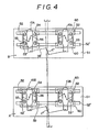
- a rear wheel measuring section A and a front wheel measuring section B that are constituted independently as shown in Fig. 4 are arranged to correspond to the wheel bases of a vehicle, the front wheels and the rear wheels are placed respectively on support bases 53, 53′ positioned on the right and left sides of the measuring sections A, B, and thereby the various tests mentioned above are carried out.
- the constitution of the measuring sections A, B is such that a pair of rails 52, 52′ are placed on rectangular fixed bases 50, 51 extending in the direction of the width of the vehicle, and are arranged in parallel along the direction (hereinafter referred to as the direction of the width of the vehicle) orthogonally to the measurement reference line Ls corresponding to the central line extending along the direction of the advance of the vehicle, the pairs of support bases 53, 53′ are arranged on the opposite sides of the measurement reference line Ls, positioning means 56 for positioning wheels 10 with the opposite sides of the wheels 10 clamped by a plurality of rollers 54, 55 provided on the support bases 53, 53′ are swingably supported on the support bases 53, 53′ through support shafts 57, and said pairs of support bases 53, 53′ are connected movably toward or away from one another by linklike connecting mechanisms 58 having fixed rotation supporting points C, C′ on the measurement reference line Ls called "equalizers.”
- the wheels on the side of the front wheels 10A and on the side of the rear wheels 10B are positioned on the support bases 53, 53′ by the positioning means 56, then following the positioning operation, the connecting mechanisms 58 move symmetrically the pairs of support bases 53, 53′ toward or away from the fixed rotation supporting points C, C′ thereby aligning the measurement reference line Ls connecting the fixed rotation supporting points C, C′ with the vehicle center line Lc, and due to this alignment the above-mentioned various test items that are tested with the wheels 10 of the vehicle being means to be detected can be tested precisely.
- vehicles include, for example, attaching position errors of front wheels 10A and rear wheels 10B due to various production conditions, and cannot be produced with the attaching positions of wheels of the vehicles being very precise, and therefore if, with the state including such errors, the wheels are clamped forcibly on the support bases 53, 53′ whose positions are restricted approximately to the shape of the letter H by the rails 52, 52′ and the line C-C′ connecting the rotation supporting points, the vehicle center line Lc and the measurement reference line Ls may become out of alignment in some cases, and precise measurement becomes difficult.
- the object of the present invention is to provide a vehicle composite test apparatus wherein the vehicle center line Lc and the measurement reference line Ls can easily and automatically be aligned in any of the case when vehicles having different widths are to be tested, the case when vehicles having attaching position errors or the like between the left and right wheels, and the case when the vehicle is dislocated to one side, or is introduced obliquely.
- the invention has to provide a parallel moving mechanism that can move long moving platforms in parallel precisely and smoothly that are to be incorporated in a vehicle composite test apparatus, etc., particularly to provide a parallel moving mechanism for long moving platforms that can move the long moving platforms in parallel along beams easily even in the case wherein a force is applied in the direction of the width of the vehicle from one side of the moving platform, and in the case wherein rollers that will be traveled on the beams are loosened themselves or have, for example, sliding resistance.
- the invention has to provide a tire guide apparatus wherein in order to introduce tires to the tire setting positions of the above test apparatus with good precision, pairs of rollers are arranged along the direction of the advance of the tires with the rollers converged toward the forward, and the vehicle center is aligned with the center of the roller pairs while the tires are moved onto the paris of the rollers, particularly to provide a tire guide apparatus that can easily and precisely guide and control various tires of vehicles ranging from small vehicles to large vehicles to the center positions of roller pairs without increasing the diameter of the rollers.
- the present invention provides a lock mechanism of a pair of active juxtaposed rollers used in a vehicle test apparatus that allows lock operation to be performed positively even if gears concentrically fixed to the rollers are rotated with the phases shifted.
- the first feature of the first embodiment lies in that pairs of support bases 53, 53′ on the side of front wheels and on the side of rear wheels are not integrated onto fixed bases through rails as in the above prior technique, but a pair of moving platforms 1, 2 arranged in parallel on the opposite sides of the measurement reference line Ls are prepared, the support bases 53, 53′ on the side of left wheels and on the side of right wheels are attached to prescribed positions preferably corresponding to the wheel bases on the moving platforms 1, 2, the support bases 53, 53′ attached onto the moving platforms 1, 2 are connected through pantograph-like moving mechanisms 9, 9′, and the support bases 53, 53′ can be moved in the direction of the width of a vehicle symmetrically toward or away from supporting points 9a approximately positioned on the measurement reference line Ls.
- the second feature lies in that the pair of moving platforms 1, 2 can also be moved in the direction of the width of the vehicle, and also connected through pantograph-like moving mechanisms 8, 8′ so that the moving mechanisms 1, 2 can be moved in the direction of the width of a vehicle symmetrically toward or away from supporting points 8a set at positions similar to the above positions.
- the third feature lies in that at least one pair of guide rollers 4 are set on each of the moving platforms 1, 2 on the inlet side of the support bases 53, 53′ with the guide rollers converged toward the support bases 53, 53′, and the moving platforms 1, 2 can be moved by the force given to the moving platforms 1, 2 through the guide rollers 4 toward or away from one another correspondingly to the width of the vehicle to be tested when the vehicle is advanced.
- the moving platforms 1, 2 capable being moved symmetrically toward or away from the measurement reference line Ls are provided, by moving the moving platforms 1, 2 themselves toward or away from one another correspondingly to the vehicle coming onto the moving platforms 1, 2, particularly by moving the moving platforms 1, 2 by the force given to the moving platforms 1, 2 through the guide rollers 4 toward or away from one another correspondingly to the width of the vehicle to be tested when the vehicle is advanced, the vehicle center line Lc and the measurement reference line Ls can be aligned easily and automatically, particularly, even if the vehicle is introduced with the vehicle dislocated to one side, or is introduced obliquely.
- the support bases 53, 53′ on which the above tests will be carried out are placed on the moving platforms 1, 2 movably toward or away from one another by substantially common supporting points 8a, 9a, by arranging the support bases 53, 53′ respectively for front wheels and rear wheels immediately after the outlets of the guide rollers 4, tires can be placed on the support bases 53, 53′ by the guide rollers 4 with the center line Lc and the measurement reference line Ls aligned, so that tests which use the tires 10 as means to be detected can be carried out precisely even in the case of vehicles different in width, or having, for example, attaching position errors between the left and right wheels.
- Each of the moving mechanisms 8, 9 is composed of a double pantograph mechanism whose supporting points 8a, 9a are substantially coincident, and it is preferable that by using the pantographs, the support bases 53, 53′ are connected and the pair of moving platforms 1, 2 are connected.
- the alignment of the center (the measurement reference line Ls) of the moving platforms 1, 2 with the center line Lc is made easier, and the measurement of the alignment and toe can be carried out more precisely.
- the moving platforms 1, 2 while the position of the vehicle introduced along the approach paths provided on the moving platforms 1, 2 is controlled by guide roller pairs 12 converged forward, the moving platforms 1, 2 are moved in parallel symmetrically toward or away from the measurement reference line Ls approximately correspondingly to the distance of the width of the vehicle, and thereafter the left and right wheels 10 are placed on the support bases 53, 53′.
- the support bases 53, 53′ on the side of the front wheels 10A, and the on the side of the rear wheels 10B are also moved symmetrically toward or away from one another by clamping the wheels 10 by the positioning means 56, for example the attaching position errors of the front wheels 10A and the rear wheels 10B are absorbed thereby the measurement can be precise, but in order to attain the above operation smoothly, it is required to assume that the moving platforms 1, 2 are moved in parallel on the beams 5, 6, since the moving platforms 1, 2 are long, and since for example the rollers 7A, 7B on which the beams 5, 6 will be traveled are loosened themselves or have sliding resistance, and since the vehicle approaches from one side of the moving platforms 1, 2, the force given to the moving platforms 1, 2 in the direction of the width of the vehicle will be applied much on the side of the beam 5, and therefore it is substantially impossible to move the moving platforms 1, 2 in parallel on the beams smoothly only by the rollers 7a, 7B, so that the above techniques have been very difficult to be used in practice.
- a parallel moving mechanism for the long moving bodies 1, 2 whose feature lies in that operation transferring shafts 21 extending along the longitudinal direction of the moving bodies 1, 2 and supported rotatably on the moving platforms 1, 2 are provided, that a plurality of link bodies 22, 23 are arranged along the longitudinal surfaces of the beams, and that one side of each of the link bodies 22, 23 is fixed to each of the operation transferring shafts 21 and the other side is pivotally supported on the beam.
- the long moving bodies can be moved in parallel along the beams easily, and particularly it is quite suitable as a parallel moving mechanism for long moving bodies that will be incorporated into a vehicle composite test machine wherein moving bodies are moved in parallel while a vehicle approaches from one side as described above.
- link bodies 22, 23 are composed of a pair of arms 24, 25 pivotally supported, the present invention is not limited to it.
- a guide apparatus comprising pairs of rollers which are arranged on approach paths positioned on the inlet side of the test apparatus along the approach direction with them converged forward is provided, while a vehicle is being mounted onto the pairs of rollers through the tires, the vehicle is guided and controlled with the vehicle being moved to the center position of the rollers, and is placed on the tire setting positions 8 on the test base, more particularly on active juxtaposed roller pairs.
- the conventional tire guide apparatus 1′ as shown in Fig.
- pairs of guide rollers 40 are arranged along the direction of the approach of tires with them converged forward to allow the movement and control toward the center positions, but in the above test apparatus, since various many vehicles different in the type of tires 10A, 10B ranging from small vehicles to large vehicles are tested, correspondingly it is required that the guide apparatus 40 can guide and control smoothly the tires 10A, 10B of any of small vehicles and large vehicles, but since the width of the tires 10A , 10B scatters from 125 mm to 245 mm that is about twice as much as the former, it is difficult to make easy the guide and control to meet it.
- the guide apparatus 40 guides and controls the tires 10A, 10B while the curvature surfaces of opposed rollers are used to press one of the curvature surfaces against the tire side surface, its preferable shape is required to be constituted in such a manner that, as shown in Fig. 11, the distance between the side surfaces of rollers on the inlet side is set larger than the width of the tires 10A, 10B to facilitate the approach of the tires 10A, 10B between the rollers, and that the tires 10A, 10B can be mounted onto the curvature surfaces of the opposed rollers in order to facilitate the movement of the tires 10A, 10B to the center positions on the outlet side of the rollers.
- At least the central interval RC of the rollers near the outlet side is set larger than the width of the tire 10A of a large vehicle, and that the roller side surface interval RW near the outlet side is set smaller than the width of the tire 10B of a small vehicle.
- the feature of the present third embodiment lies in that as shown in Figs. 8 to 10 a plurality of pairs of rollers 4a, 4b are placed along the tire approach direction L with them spaced, converged forward, and arranged stepwise upward, and particularly the interval of the rollers 4a, 4b at least near the outlet is successively increased toward the upper rollers 4a.
- the rollers 4a, 4b may be set two-stepwise as shown by an embodiment given later and also may be set three-stepwise.
- the guide and control when the tire 10B for small vehicles has come in, the guide and control is effected by the lower rollers 4b with the side surfaces restricted, and when the tire 10A for large vehicles has come in, while the tires are being mounted onto the lower rollers 4a, the guide and control is effected by the upper roller 4a with the side surfaces restricted, so that when the diameter of the rollers 4a, 4b is made smaller, smooth control can be made.
- the tires can be introduced precisely to the tire setting positions of the test base, and the tires 10A, 10B can be retracted easily.
- various tires for small vehicles and large vehicles can be guided and controlled easily and precisely to the center positions of the rollers without increasing the diameter of the rollers, and as a result, the tire side surfaces can perfectly be prevented for example from being scarred or damged at the time of the guide and control.
- the active juxtaposed rollers 61,62 used for the test apparatus give a rotational force to the placed tire 10A, and is provided with a lock means, and while the lock means prevents the juxtaposed rollers from rotating idly, the active juxtaposed rollers 61,62 cause, for example, the tire 10A placed on the rollers to be removed.
- a device which is constituted in such a manner that gears are concentrically fixed to side ends of the rollers, and a pair of lock members having meshing sections capable of meshing with the gears are provided, are arranged in positions where the lock members can face the gears on the side of the side ends of the rollers, and can integrally be reciprocated in parallel with the axes of the rollers by a reciprocating means including a fluid cylinder, etc. so that the lock members and the gears may be meshed at the time of the forward movement or the backward movement to effect locking, and the reverse action may allow unlocking.
- rollers are not rotated synchronously necessarily, and the gears attached to the rollers include assembling errors more or less, it is seldom that the gears are rotated with the phases registered when the rollers are rotated, and generally they are rotated with the phases shifted.
- the lock members can integrally be reciprocated by a reciprocating means, in other words, the locking and unlocking can be simultaneously carried out, in the case of a pair of gears whose phases are shifted, even if one side is locked, it is impossible to lock the other side at the same time.
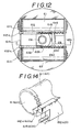
- the feature of the present fourth embodiment lies in that, as shown in Figs. 12 to 14, in a lock mechanism of a pair of active juxtaposed rollers 61, 62 wherein a pair of lock members 612, 622 engageable with gears 611, 621 concentrically fixed respectively to the active juxtaposed rollers 61, 62 can be reciprocated along the roller axes by guide means 613, 623, at the time when the lock is released the lock members 612, 622 are integrally moved in the direction wherein they are disengaged with the gears 611, 621 whereas at the time when the locking is effected the locking is not effected integrally since the phases of the gears 611, 621 fixed respectively to the rollers 61,62 are different, and energizing means 614, 624, preferably resilient members, connected respectively to the lock members 612, 622 are used to effect locking independently with respect to each other.
- rollers 61, 62 effect the locking by independent energizing forces, it is very difficult to throw engaging members 612a, 622a of the lock members 612, 622 into the rotating tooth surfaces.
- the second feature of the embodiment lies in that even when, in the case, at the time of locking, while the lock members 612, 622 and the gears 611, 621 are being allowed to engage imperfectly, the the lock members 612, 622 and the gears 611, 621 are engaged imperfectly by the energizing forces of the energizing means 614, 624, the rollers 61,62 can be rotated desirable angles against the energizing forces of the energizing means 14, 24.
- the lock members 612, 622 and the gears 611, 621 can smoothly be engaged respectively by the slight idle rotation of the rollers 61, 62 at the time when the tires are removed or by the inertia force after the stop of the rotation of the rollers 61, 62.
- the engagement can be effected separately and with a time-lag even when the phases of the gears 611, 621 are different since the lock members 612, 622 are pulled respectively by the energizing members 614, 624.
- the energizing means 614, 624 are not limited necessarily to resilient members, and air cylinders 69 whose pressure is weakened can be used therefor if the rollers 61, 62 can be rotated desirable angles against the energizing forces of the energizing means 614, 624.
- the lock means comprises a resilient member capable of abutting against the gear circumferential surface, there is no fear that at the time of locking, for example, the tooth surface is damaged or dragged.
- the lock/release mechanism of the present invention may be composed of only a fluid cylinder, a pair of resilient members, etc., it can be arranged in such a limited space between the pair of rollers that the rotational force can be given to the tire.
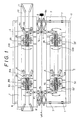
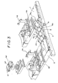
- Figs. 1 to 3 show a vehicle composite test apparatus of an embodiment of the present invention.
- the overall constitution will briefly be described with reference to Fig. 1.
- Two parallel fixed beams 5, 6 are arranged orthogonally to the direction in which a vehicle will come in, that is, along the width of the vehicle, and are spaced apart from each other, and long moving platforms 1, 2 placed on the beams 5, 6 can be moved in parallel through a plurality of rollers 7.
- the moving platforms 1, 2 are arranged on the opposite sides of the measurement reference line Ls, cover bodies 12 to which vehicle incoming paths and guide roller pairs 4, 11 that will be described later are attached are mounted on the moving platforms 1, 2, prescribed parts of the cover bodies 12, the distance between them corresponding to wheel bases, are cut to form rectangular recesses, a pair of rails 13 are extended through the rectangular recesses in the direction of the width of the vehicle, and test units 50 including the above-mentioned support bases 53, 53 are arranged on the rails 13 movably in the direction of the width of the vehicle.
- the moving platforms 1, 2 are connected through a pair of pantographs 8, 8′ that can be extended from or contracted to the supporting shafts 8a positioned on the measurement reference line Ls so that the moving platforms 1, 2 can be moved in reference to the supporting shafts 8a in the direction of the width of the vehicle by the extension or contraction of the pantographs 8, 8′.
- Each of the above-mentioned test units 50 is constituted in such a manner that a drive roller pair 60, the above-mentioned positioning means 56, a camber sensing roller 61, etc. that will be used for carrying out basic tests about the braking, speed, etc.
- the pantographs 8, 8′, 9, 9′ may be pivotally supported on beams 15 that serve as their fixing means and are fixed to the bottom of the apparatus body as shown in Fig. 2, or may be supported on the floated supporting points 8a, 9a, if they constitute pantograph mechanisms.
- the moving platforms 1, 2 can parallelly be moved positively toward or away from the supporting points 8a, 9a, and therefore the alignment and toe measurement by the pantographs 9 connecting the support bases 53, 53′ can be carried out very precisely.
- Each of the cover bodies 12 has the first guide roller pair 11 on the inlet side that are arranged with the forward ends converged, and the second guide roller pairs 4 on the inlet side of the drive roller pairs that are arranged with the forward ends converged and with the space between them being set smaller than that between the first guide rollers 11 so that the side surfaces of the tires 10 can ride on them.
- the second guide roller pair 4 comprise guide roller pairs 4a, 4b with one over the other and the forward ends directed downward.
- the moving platforms 1, 2 are precisely moved symmetrically toward or away from the measurement reference line Ls with the moving platforms 1, 2 kept in parallel so that the distance between them may correspond to the width of the vehicle, and then all the left and right wheels 10 are positioned on the drive roller pairs of the test units 50 in place.
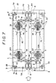
- Figs. 5 to 7 show a parallel moving mechanism of moving platforms of the present second embodiment, and the long moving platforms 1, 2 can be traveled, through a plurality of rollers 7A, 7B, on two fixed beams 5, 6 that are positioned on the opposite sides of the length of the arrangement and are in parallel with the width of the vehicle.
- the rollers 7A, 7B comprise flanged guide rollers to effect the guide and control.
- the moving platforms 1, 2 are provided with side frames 26 on the longitudian outer end sides between the beams 4, 5, and horizontal fixed plates 28 each having a bearing 27 fixed on the undersurface are fixed near the side walls of the beams 4, 5 of the inner walls of the side frames 26.
- brackets 29 are attached to the beams 5, 6 at prescribed sections on their opposed side surfaces, and one end of each of link bodies 22, 23 that will be described later is pivotally supported by each of shafts 29a projected from the brackets 29.
- Each of the link bodies 22, 23 comprises a pair of arms 24, 25 whose ends are pivotally supported together, and can be bent in planes that are parallel with the side walls of the beams 4, 5, and the other ends are fixed to shaft ends of operation transferring shafts 21 that will be described later.
- the operation transferring shafts 21 are extended linearly along the length of the moving platforms 1, 2 between the opposed beams 4, 5, and the front and rear sides of the operation transferring shafts 21 are pivotally supported on bearings 27 on the sides of the moving platforms 1, 2.
- Figs. 8 to 10 show a guide apparatus related to an embodiment of the present invention.
- This apparatus comprises two pairs of roller shafts 4a, 4b which have the same diameter and the same length, and are arranged with the forward ends converged along the advance direction L, and pairs of brackets 4c, 4e stood vertically on bases 4b for supporting rotatably the rollers 4a, 4b.
- the side surface interval FW1 of the roller pair 4b, positioned lower, on their inlet side is set wider than the maximum tire width W1, and the interval between the rollers 10 and the shaft diameter thereof are selected such that the minimum tire width W2 which will come into the guide apparatus 1 is positioned between the side surface interval RW1 and the central interval RC1 of the lower roller pair 4a near the outlet side.
- angles of the rollers 4b with the direction of the advance of the vehicle are set approximately symmetrically with respect to the transversal direction
- angles of the rollers 4b with the direction of the advance of the vehicle are not necessarily set symmetrically with respect to the vertical direction, and for example as shown in Fig. 9 (a) and (b), the roller shaft 4b positioned outside is inclined downward in the tire advance direction L from the inlet side toward the outlet side while the roller shaft 4b positioned inside is extended approximately horizontally.
- the interval between the rollers 4a positioned above is set wider than that of the rollers 4b positioned below with their forward ends converged, and the interval is not necessarily uniform relative to the rollers 4b positioned below, and is set to increase near the outlet more than on the inlet side.
- the central interval RC2 of the upper rollers 4a near the outlet side is set approximately equal to or wider than the maximum tire width W1, and the side surface interval RW2 is set smaller than the maximum tire width W1.
- the upper rollers 4a are inclined downward in the tire advance direction L from the inlet side toward the outlet side and are supported on the brackets 4c, 4e.
- the operation of the present invention can be attained smoothly.
- Figs. 12 to 14 shows an active juxtaposed roller pair of an embodiment of the invention.
- reference numeral 68 indicates a disklike base plate rotatable on a support shaft 64, a pair of support plates 619, 629 are stood in parallel on the left and right sides of the base plate 68, and a pair of rollers 61, 62 are pivotally supported between the support plates 619, 629.
- rollers 61, 62 are arranged in parallel with one over the other and symmetrically with a support shaft64 between them, and spur gears 611, 621 having a diameter equal to or a little larger than the diameter of the rollers 61, 62 are fixed concentrically on one side of the rollers 61, 62.
- an air cylinder 69 fixed approximately at the central position of the support plates 619, 629 is placed in the central space between the rollers 61, 62, and a pair of cylinder pistons 618, 628 extending axially of the rollers 61, 62 along and near the rollers 61, 62 are connected through a bar 691 extending normally to the cylinder 69, and a pair of lock members 612, 622 having meshing sections 611a, 621a projected therefrom and meshable with the gears 611, 621 are provided to the forward ends of the pistons.
- a pair of guide shafts 613,623 for sliding axially the rollers 61, 62 with the positions of the lock members 612, 622 controlled are extended through below the lock members 612, 622, and the opposite ends of the guide shafts 613,623 are fixed to the support plates 619, 629.
- the air cylinder 69 uses a single-acting type air cylinder 69 that can be moved forward in the direction shown by the arrow by the application of pressure, and can be moved backward only by an external force with the air pressure released and with it freed.
- Coiled springs 614, 624 are connected between the lock members 612, 622 and the support members in such a way that when the air cylinder 69 is freed, the lock members 612,622 may be pulled.
- Reference numerals 615,625 indicate stoppers for restricting the backward stroke of the lock members 612,622.
Landscapes
- Physics & Mathematics (AREA)
- General Physics & Mathematics (AREA)
- Automobile Manufacture Line, Endless Track Vehicle, Trailer (AREA)
- Body Structure For Vehicles (AREA)
Applications Claiming Priority (8)
| Application Number | Priority Date | Filing Date | Title |
|---|---|---|---|
| JP16129588U JPH0536196Y2 (de) | 1988-12-14 | 1988-12-14 | |
| JP161296/88 | 1988-12-14 | ||
| JP161294/88 | 1988-12-14 | ||
| JP313849/88 | 1988-12-14 | ||
| JP161295/88 | 1988-12-14 | ||
| JP16129688U JPH0522855Y2 (de) | 1988-12-14 | 1988-12-14 | |
| JP16129488U JPH0536195Y2 (de) | 1988-12-14 | 1988-12-14 | |
| JP63313849A JP2622600B2 (ja) | 1988-12-14 | 1988-12-14 | 車両複合試験装置 |
Publications (3)
| Publication Number | Publication Date |
|---|---|
| EP0373653A2 true EP0373653A2 (de) | 1990-06-20 |
| EP0373653A3 EP0373653A3 (de) | 1991-11-13 |
| EP0373653B1 EP0373653B1 (de) | 1994-04-13 |
Family
ID=27473719
Family Applications (1)
| Application Number | Title | Priority Date | Filing Date |
|---|---|---|---|
| EP89123157A Expired - Lifetime EP0373653B1 (de) | 1988-12-14 | 1989-12-14 | Vorrichtung zur Fahrzeugprüfung |
Country Status (4)
| Country | Link |
|---|---|
| US (2) | US5088320A (de) |
| EP (1) | EP0373653B1 (de) |
| CA (1) | CA2005348C (de) |
| DE (1) | DE68914616T2 (de) |
Cited By (8)
| Publication number | Priority date | Publication date | Assignee | Title |
|---|---|---|---|---|
| DE4238691A1 (de) * | 1992-11-17 | 1994-05-19 | Audi Ag | Prüfstand |
| EP0824672A1 (de) * | 1996-03-01 | 1998-02-25 | Snap-on Technologies, Inc. | Dynamometrischer prüfstand mit verwendung von seitlich beweglichen rollenvorrichtungen während der fahrzeugausrichtung |
| DE19635194C1 (de) * | 1996-09-02 | 1998-04-09 | Roland Mueller | Fahrzeugprüfvorrichtung |
| ES2140990A1 (es) * | 1996-01-11 | 2000-03-01 | Arriola Jose Luis Unamuno | Maquina comprobadora del funcionamiento de vehiculos automoviles. |
| DE19923340C2 (de) * | 1999-05-21 | 2003-03-27 | Audi Ag | Vorrichtung zum Halten eines Fahrzeuges mit an einer Radachse eines Fahrzeugrades angreifenden Fesselungsmitteln |
| EP1253416A3 (de) * | 2001-04-25 | 2004-06-09 | MAHA Maschinenbau Haldenwang GmbH & Co. KG | Rollenprüfstand für Kraftfahrzeuge |
| WO2005015150A1 (de) * | 2003-07-25 | 2005-02-17 | Schenck Pegasus Gmbh | Vorrichtung zur stationären prüfung von fahrzeugen |
| FR2942039A1 (fr) * | 2009-02-11 | 2010-08-13 | Daniel Frederic Fuchs | Banc d'essais pour vehicules |
Families Citing this family (25)
| Publication number | Priority date | Publication date | Assignee | Title |
|---|---|---|---|---|
| CA2005348C (en) * | 1988-12-14 | 1994-09-20 | Yutaka Fukuda | Vehicle composite test apparatus |
| US5297344A (en) * | 1990-07-05 | 1994-03-29 | Anzen Motor Car Co., Ltd. | Wheel examining apparatus |
| AU2049792A (en) * | 1991-08-30 | 1993-03-04 | Bear Automotive Service Equipment Company | Wheel alignment system |
| US5257458A (en) * | 1991-10-02 | 1993-11-02 | Arthur Koerner | Method and apparatus for determining caster and steering axis inclination angles |
| FR2719374B1 (fr) * | 1994-04-28 | 1996-07-05 | Muller Bem | Dispositif et procédé de contrôle géométrique de véhicules à roues. |
| US5465615A (en) * | 1994-04-28 | 1995-11-14 | Mts Systems Corporation | Loading assembly for a vehicle spindle test fixture |
| JP3424986B2 (ja) * | 1994-07-29 | 2003-07-07 | 安全自動車株式会社 | ホイールアライメント検査装置 |
| US5513438A (en) * | 1994-08-29 | 1996-05-07 | Emmons; J. Bruce | Vehicle wheel alignment system |
| US6070332A (en) * | 1996-10-18 | 2000-06-06 | Aim Automotive Integrated Manufacturing, Inc. | Wheel alignment apparatus |
| DE19822922B4 (de) * | 1998-05-22 | 2006-09-28 | Audi Ag | Prüfstand für ein Kraftfahrzeug |
| US6257055B1 (en) | 1999-05-04 | 2001-07-10 | Mts Systems Corporation | Loading assembly for a vehicle spindle test fixture |
| JP2001018830A (ja) * | 1999-07-06 | 2001-01-23 | Bridgestone Corp | ホイールアライメント調整装置 |
| JP2001030945A (ja) * | 1999-07-16 | 2001-02-06 | Bridgestone Corp | ホイールアライメント調整装置 |
| JP2001033234A (ja) * | 1999-07-16 | 2001-02-09 | Bridgestone Corp | タイヤ位置検出装置及びホイールアライメント調整装置 |
| US6640638B1 (en) | 1999-09-03 | 2003-11-04 | Mts Systems Corporation | Loading assembly for a vehicle spindle test fixture |
| ITVE20000043A1 (it) * | 2000-10-23 | 2002-04-23 | Eride Rossato | Attrezzatura per effettuare misurazioni della geometria delle sospensioni di un autoveicolo |
| US6564414B1 (en) * | 2002-02-21 | 2003-05-20 | Donald Lester Jamison | Portable ramp with pad |
| JP4285392B2 (ja) * | 2004-11-04 | 2009-06-24 | トヨタ自動車株式会社 | 車両正対装置 |
| DE102005056655A1 (de) * | 2005-11-28 | 2007-05-31 | Sherpa Autodiagnostik Gmbh | Prüfvorrichtung für Fahrzeuge, um ein etwaiges Achsspiel bzw. Gelenkspiel sichtbar zu machen |
| JP4240054B2 (ja) * | 2006-04-24 | 2009-03-18 | トヨタ自動車株式会社 | 車両正対装置および車両正対方法 |
| US11609573B2 (en) * | 2018-10-30 | 2023-03-21 | Florida Power & Light Company | Method for the automated docking of robotic platforms |
| CN110523454B (zh) * | 2019-09-27 | 2024-03-19 | 洛阳合能电气有限公司 | 一种移动支撑装置和车辆性能试验平台 |
| DE102020122983A1 (de) | 2020-09-02 | 2022-03-03 | Hochschule für angewandte Wissenschaften Kempten, Körperschaft des öffentlichen Rechts | System, vorrichtung und verfahren zum abstützen eines fahrzeugreifens gegen einen untergrund |
| CN112147284B (zh) * | 2020-10-09 | 2022-10-28 | 上海公孚机动车检测股份有限公司 | 一种机动车环保检测装置 |
| CN117073503B (zh) * | 2023-10-19 | 2024-02-06 | 山东宏冠车辆有限公司 | 一种测量半挂车轴距的工装 |
Family Cites Families (8)
| Publication number | Priority date | Publication date | Assignee | Title |
|---|---|---|---|---|
| US1911725A (en) * | 1933-05-30 | taber | ||
| US2020614A (en) * | 1932-07-30 | 1935-11-12 | Miller Michael | Apparatus for truing the wheels of motor vehicles |
| US2758385A (en) * | 1950-06-30 | 1956-08-14 | Bear Mfg Co | Vehicle turn indicating gauge |
| US2720036A (en) * | 1953-07-20 | 1955-10-11 | Berger Herman | Combined roll-on lift and alignment machine for automobiles |
| US3458013A (en) * | 1967-03-24 | 1969-07-29 | Fmc Corp | Multi-purpose vehicle lift |
| US3494945A (en) * | 1967-11-14 | 1970-02-10 | Rohm & Haas | Alkylene bis-iminodithiocarbonic acid chelates |
| DE2321012A1 (de) * | 1973-04-26 | 1974-11-14 | Hans O Haupt | Vorrichtung und verfahren zum messen und einstellen der radaufhaengung von kraftfahrzeugen |
| CA2005348C (en) * | 1988-12-14 | 1994-09-20 | Yutaka Fukuda | Vehicle composite test apparatus |
-
1989
- 1989-12-13 CA CA002005348A patent/CA2005348C/en not_active Expired - Lifetime
- 1989-12-14 US US07/450,304 patent/US5088320A/en not_active Expired - Lifetime
- 1989-12-14 DE DE68914616T patent/DE68914616T2/de not_active Expired - Lifetime
- 1989-12-14 EP EP89123157A patent/EP0373653B1/de not_active Expired - Lifetime
-
1991
- 1991-12-10 US US07/804,367 patent/US5131267A/en not_active Expired - Lifetime
Non-Patent Citations (2)
| Title |
|---|
| BROWN BOVERI REVIEW, vol. 73, no. 3, March 1986, pages 151-156, Baden, CH; R. GAA: "Four-roller test rig for four-wheel drive vehicles" * |
| MACHINE DESIGN, vol. 60, no. 9, 21st April 1988, pages 106-107, Cleveland, Ohio, US; "Electric dynamometer compresses development cycle" * |
Cited By (9)
| Publication number | Priority date | Publication date | Assignee | Title |
|---|---|---|---|---|
| DE4238691A1 (de) * | 1992-11-17 | 1994-05-19 | Audi Ag | Prüfstand |
| ES2140990A1 (es) * | 1996-01-11 | 2000-03-01 | Arriola Jose Luis Unamuno | Maquina comprobadora del funcionamiento de vehiculos automoviles. |
| EP0824672A1 (de) * | 1996-03-01 | 1998-02-25 | Snap-on Technologies, Inc. | Dynamometrischer prüfstand mit verwendung von seitlich beweglichen rollenvorrichtungen während der fahrzeugausrichtung |
| EP0824672A4 (de) * | 1996-03-01 | 1998-06-10 | Snap On Tech Inc | Dynamometrischer prüfstand mit verwendung von seitlich beweglichen rollenvorrichtungen während der fahrzeugausrichtung |
| DE19635194C1 (de) * | 1996-09-02 | 1998-04-09 | Roland Mueller | Fahrzeugprüfvorrichtung |
| DE19923340C2 (de) * | 1999-05-21 | 2003-03-27 | Audi Ag | Vorrichtung zum Halten eines Fahrzeuges mit an einer Radachse eines Fahrzeugrades angreifenden Fesselungsmitteln |
| EP1253416A3 (de) * | 2001-04-25 | 2004-06-09 | MAHA Maschinenbau Haldenwang GmbH & Co. KG | Rollenprüfstand für Kraftfahrzeuge |
| WO2005015150A1 (de) * | 2003-07-25 | 2005-02-17 | Schenck Pegasus Gmbh | Vorrichtung zur stationären prüfung von fahrzeugen |
| FR2942039A1 (fr) * | 2009-02-11 | 2010-08-13 | Daniel Frederic Fuchs | Banc d'essais pour vehicules |
Also Published As
| Publication number | Publication date |
|---|---|
| DE68914616T2 (de) | 1994-11-03 |
| EP0373653A3 (de) | 1991-11-13 |
| EP0373653B1 (de) | 1994-04-13 |
| DE68914616D1 (de) | 1994-05-19 |
| US5088320A (en) | 1992-02-18 |
| CA2005348A1 (en) | 1990-06-14 |
| US5131267A (en) | 1992-07-21 |
| CA2005348C (en) | 1994-09-20 |
Similar Documents
| Publication | Publication Date | Title |
|---|---|---|
| EP0373653B1 (de) | Vorrichtung zur Fahrzeugprüfung | |
| EP1091825B1 (de) | Vorrichtung zum reibschweissen | |
| US5231870A (en) | Vehicle composite test apparatus | |
| EP0738673B1 (de) | Fördersystem | |
| EP0210974A1 (de) | Industrieroboter | |
| MXPA02008776A (es) | Registro longitudinal de precision de tambor para construccion de neumatico, para estacion de trabajo de sistema de construccion de neumatico automatizado. | |
| JP3115601B2 (ja) | 自動車輛の関節継手の弛みを決定するため及びかじ取り角度を測定するための装置 | |
| CN1982850B (zh) | 运输和安装测量机构的保险装置 | |
| US4782760A (en) | Vehicle precision location assembly | |
| US5867905A (en) | Apparatus for manufacturing a truss | |
| KR102538998B1 (ko) | 금속 메시 보강재 생산 디바이스 | |
| US20060108131A1 (en) | Apparatus and method for measuring position of wheel inclination angle adjustment member, shaft-like work adjuster, and shaft-like work setting method | |
| EP0594163B1 (de) | Einrichtung zur Vermessung der Achsgeometrie an den Radachsen von Kraftfahrzeugen bei drehenden Rädern | |
| DE102015210914B4 (de) | Koordinatenmessgerät mit einer beweglichen Traverse sowie Verfahren zum Herstellen eines derartigen Koordinatenmessgeräts | |
| JPH0920273A (ja) | 車両検査装置 | |
| JP2622600B2 (ja) | 車両複合試験装置 | |
| DE3844887C2 (de) | Radprüfvorrichtung mit Andruckrollen | |
| US4722476A (en) | Apparatus for axially aligning a vehicle | |
| US4646649A (en) | Driverless vehicle with floating mounted substrate, and precision stop/locator assembly | |
| JPH0465648A (ja) | 車輪検査システム | |
| JP3006854B2 (ja) | 車輪検査装置 | |
| JPH0536195Y2 (de) | ||
| JPH0522855Y2 (de) | ||
| JPS6135384Y2 (de) | ||
| AU674287B2 (en) | Apparatus for manufacturing a truss |
Legal Events
| Date | Code | Title | Description |
|---|---|---|---|
| PUAI | Public reference made under article 153(3) epc to a published international application that has entered the european phase |
Free format text: ORIGINAL CODE: 0009012 |
|
| AK | Designated contracting states |
Kind code of ref document: A2 Designated state(s): DE GB |
|
| 17P | Request for examination filed |
Effective date: 19901227 |
|
| PUAL | Search report despatched |
Free format text: ORIGINAL CODE: 0009013 |
|
| AK | Designated contracting states |
Kind code of ref document: A3 Designated state(s): DE GB |
|
| 17Q | First examination report despatched |
Effective date: 19921125 |
|
| GRAA | (expected) grant |
Free format text: ORIGINAL CODE: 0009210 |
|
| AK | Designated contracting states |
Kind code of ref document: B1 Designated state(s): DE GB |
|
| REF | Corresponds to: |
Ref document number: 68914616 Country of ref document: DE Date of ref document: 19940519 |
|
| PLBE | No opposition filed within time limit |
Free format text: ORIGINAL CODE: 0009261 |
|
| STAA | Information on the status of an ep patent application or granted ep patent |
Free format text: STATUS: NO OPPOSITION FILED WITHIN TIME LIMIT |
|
| 26N | No opposition filed | ||
| REG | Reference to a national code |
Ref country code: GB Ref legal event code: IF02 |
|
| PGFP | Annual fee paid to national office [announced via postgrant information from national office to epo] |
Ref country code: DE Payment date: 20090217 Year of fee payment: 20 |
|
| PGFP | Annual fee paid to national office [announced via postgrant information from national office to epo] |
Ref country code: GB Payment date: 20081121 Year of fee payment: 20 |
|
| REG | Reference to a national code |
Ref country code: GB Ref legal event code: PE20 Expiry date: 20091213 |
|
| PG25 | Lapsed in a contracting state [announced via postgrant information from national office to epo] |
Ref country code: GB Free format text: LAPSE BECAUSE OF EXPIRATION OF PROTECTION Effective date: 20091213 |