EP0373407A1 - Dispositif de commande à distance pour l'émission de commandes - Google Patents
Dispositif de commande à distance pour l'émission de commandes Download PDFInfo
- Publication number
- EP0373407A1 EP0373407A1 EP89121799A EP89121799A EP0373407A1 EP 0373407 A1 EP0373407 A1 EP 0373407A1 EP 89121799 A EP89121799 A EP 89121799A EP 89121799 A EP89121799 A EP 89121799A EP 0373407 A1 EP0373407 A1 EP 0373407A1
- Authority
- EP
- European Patent Office
- Prior art keywords
- remote control
- control transmitter
- housing
- transmitter
- gravity
- Prior art date
- Legal status (The legal status is an assumption and is not a legal conclusion. Google has not performed a legal analysis and makes no representation as to the accuracy of the status listed.)
- Granted
Links
- 230000005540 biological transmission Effects 0.000 title claims abstract description 11
- 230000005484 gravity Effects 0.000 claims description 45
- 239000007788 liquid Substances 0.000 claims description 15
- 230000001133 acceleration Effects 0.000 claims description 9
- 230000005855 radiation Effects 0.000 claims description 7
- 238000013016 damping Methods 0.000 claims description 3
- 230000001419 dependent effect Effects 0.000 abstract description 10
- 210000000707 wrist Anatomy 0.000 abstract 1
- 230000015654 memory Effects 0.000 description 4
- 238000013459 approach Methods 0.000 description 2
- 230000000694 effects Effects 0.000 description 2
- 230000010355 oscillation Effects 0.000 description 2
- 238000009736 wetting Methods 0.000 description 2
- 230000005670 electromagnetic radiation Effects 0.000 description 1
- 230000006870 function Effects 0.000 description 1
- 238000005259 measurement Methods 0.000 description 1
- QSHDDOUJBYECFT-UHFFFAOYSA-N mercury Chemical compound [Hg] QSHDDOUJBYECFT-UHFFFAOYSA-N 0.000 description 1
- 229910052753 mercury Inorganic materials 0.000 description 1
- 238000000034 method Methods 0.000 description 1
- 239000013643 reference control Substances 0.000 description 1
- 210000003813 thumb Anatomy 0.000 description 1
Images


Classifications
-
- H—ELECTRICITY
- H01—ELECTRIC ELEMENTS
- H01H—ELECTRIC SWITCHES; RELAYS; SELECTORS; EMERGENCY PROTECTIVE DEVICES
- H01H29/00—Switches having at least one liquid contact
- H01H29/20—Switches having at least one liquid contact operated by tilting contact-liquid container
-
- G—PHYSICS
- G08—SIGNALLING
- G08C—TRANSMISSION SYSTEMS FOR MEASURED VALUES, CONTROL OR SIMILAR SIGNALS
- G08C17/00—Arrangements for transmitting signals characterised by the use of a wireless electrical link
-
- G—PHYSICS
- G08—SIGNALLING
- G08C—TRANSMISSION SYSTEMS FOR MEASURED VALUES, CONTROL OR SIMILAR SIGNALS
- G08C23/00—Non-electrical signal transmission systems, e.g. optical systems
- G08C23/04—Non-electrical signal transmission systems, e.g. optical systems using light waves, e.g. infrared
-
- H—ELECTRICITY
- H01—ELECTRIC ELEMENTS
- H01H—ELECTRIC SWITCHES; RELAYS; SELECTORS; EMERGENCY PROTECTIVE DEVICES
- H01H35/00—Switches operated by change of a physical condition
- H01H35/02—Switches operated by change of position, inclination or orientation of the switch itself in relation to gravitational field
- H01H35/025—Switches operated by change of position, inclination or orientation of the switch itself in relation to gravitational field the switch being discriminative in different directions
-
- G—PHYSICS
- G08—SIGNALLING
- G08C—TRANSMISSION SYSTEMS FOR MEASURED VALUES, CONTROL OR SIMILAR SIGNALS
- G08C2201/00—Transmission systems of control signals via wireless link
- G08C2201/30—User interface
- G08C2201/32—Remote control based on movements, attitude of remote control device
-
- H—ELECTRICITY
- H01—ELECTRIC ELEMENTS
- H01H—ELECTRIC SWITCHES; RELAYS; SELECTORS; EMERGENCY PROTECTIVE DEVICES
- H01H9/00—Details of switching devices, not covered by groups H01H1/00 - H01H7/00
- H01H9/02—Bases, casings, or covers
- H01H9/0214—Hand-held casings
- H01H9/0235—Hand-held casings specially adapted for remote control, e.g. of audio or video apparatus
-
- Y—GENERAL TAGGING OF NEW TECHNOLOGICAL DEVELOPMENTS; GENERAL TAGGING OF CROSS-SECTIONAL TECHNOLOGIES SPANNING OVER SEVERAL SECTIONS OF THE IPC; TECHNICAL SUBJECTS COVERED BY FORMER USPC CROSS-REFERENCE ART COLLECTIONS [XRACs] AND DIGESTS
- Y10—TECHNICAL SUBJECTS COVERED BY FORMER USPC
- Y10S—TECHNICAL SUBJECTS COVERED BY FORMER USPC CROSS-REFERENCE ART COLLECTIONS [XRACs] AND DIGESTS
- Y10S200/00—Electricity: circuit makers and breakers
- Y10S200/29—Ball
Definitions
- the invention relates to a remote control transmitter according to the preamble of claim 1.
- Such remote control transmitters are used to control electrical devices via a wireless connection, in particular to control photoelectric devices such as slide or film projectors, or to control consumer electronics devices, for example to control television sets or video recorders.
- Such remote control transmitters are known, for example, from the magazine Funkschau 1978, number 9, pp. 405-407 or the magazine Funkschau 1978, number 20, pp. 963-966.
- the known remote control encoders contain a keypad on the operating side of an encoder housing as an input device. By pressing individual buttons on this keypad, the user of the remote control transmitter selects control commands for setting or changing certain operating states of an electrical device controlled by the remote control transmitter.
- the control commands called up with the actuated buttons are transmitted converted signals and emitted by an infrared transmitter element to the electrical device to be controlled.
- the invention has for its object to design a remote control transmitter according to the preamble of claim 1 so that the handling of the remote control transmitter for the inexperienced user at least for the setting of essential operating conditions or operations of the device to be operated with the remote control transmitter is significantly simplified.
- This object is achieved according to the invention by the features of the characterizing part of claim 1.
- the invention is based on the experience that individual processes of daily life can be characterized by certain hand movements.
- An enlargement of an event or a forward step-by-step progression or a forward scrolling is characterized by a hand movement to the right or upwards.
- the user of a remote control transmitter according to the invention can only scroll through the functional levels of the remote-controlled device without observing the remote control transmitter himself by upward or downward hand movements.
- a right or left movement of the hand which involuntarily involves a rotation in the axis of the hand, can switch a forward or a reverse run or amplify or dampen events without having to pay attention to the remote control transmitter used .
- the operation of a remote control transmitter according to the invention requires only one hand, so that the user of such a remote control transmitter has the second hand free for other activities during its use.
- the subclaims characterize advantageous embodiments of the invention. It is particularly advantageous to use gravity switches for determining the position differences of the transmitter housing of the remote control transmitter, since gravity represents a force field that is defined for every human activity and directed towards the center of the earth. However, it is also possible to detect a pivoting movement of a remote control transmitter held in the hand of a user by means of acceleration switches with which the position difference switch arrangement of the remote control transmitter is equipped, and to derive control commands for remote control of an electrical device therefrom.
- the position difference switch arrangement of the remote control transmitter contains sensors which depend on the direction of the intensity of a particular radiation or Detect the force field and display it with an electrical signal.
- these signals remain constant over a certain period of time, according to one embodiment of the invention, they indicate a rest position of the remote control transmitter, which for him is the reference operating position. According to a further embodiment of the invention, values of these signals also form the reference values for a rest position of the remote control transmitter. If the position of the remote control transmitter changes from this rest position by a swiveling movement of the remote control transmitter held in the hand, the direction of the swivel operation is determined from the new output signals from the sensors and the associated control commands are decoded therefrom.
- a radiation or force field is, for example, the earth's magnetic field or the radiation field of a specific radiation source, for example a source of electromagnetic radiation.
- Figures 1a and 1b show a schematic representation of the side view of a remote control transmitter, which in the case of Figure 1a is pivoted upwards from its horizontal position by an angle of inclination and in the case of Figure 1b is pivoted downwards by an angle of inclination a from the horizontal position is.
- the encoder housing 1 is cut open along a vertical plane through the main axis 2 of the remote control transmitter, so that the essential components of the remote control transmitter can be shown schematically.
- On a plate 3 which is immovably connected to the transmitter housing, the transmitter housing by means of seated transmission elements 4, 1 Directional signal converter 5, a push button 6, a plurality of gravity switches 7, 8, 9 and a circuit arrangement 10 associated therewith are arranged.
- the remote control transmitter contains a battery 11 for the power supply.
- the gravity switches 7, 8 and 9 have a rest position, which exists when their main axis 12 is parallel to the direction of gravity 13. If one of the gravity switches 7, for example, the gravity switch 7 is pivoted from its rest position 14 in a certain direction 15 into a position 16 inclined to the rest position 7 by an angle a, the angle of inclination a of which is greater than a trigger angle a0, as shown schematically in FIG. 2, then this gravity switch generates an output signal.
- a position differential switch arrangement 17 designed with such switches can pivot the remote control transmitter out of its horizontal position, which relates to the reference operating position of the remote control transmitter represents all swiveling movements to control a remote-controlled electrical device, identified by its output signals.
- the direction signal converter which also belongs to the position difference switch arrangement 17, forms a signal characterizing the direction of the position deviation from the horizontal reference operating position of the remote control transmitter, which signal is converted as a control command by the signal converter circuit 5 into a transmission signal for the transmission elements 4.
- the user of the remote control transmitter holds this remote control transmitter in one hand in such a way that he can use the thumb 18 of this hand to actuate the pushbutton 6 of a switch 19 of the remote control transmitter which protrudes from the transmitter housing 1.
- the position difference switch arrangement 17 of the remote control transmitter is switched on, so that it can recognize a pivot position of the hand-held remote control transmitter as a result of a pivoting movement of the hand of the user and can form a control command therefrom.
- the remote control transmitter held in a horizontal position is pivoted to the right or to the left, the remote control transmitter is rotated by an involuntary additional rotation of the hand when the hand is pivoted about its main axis 2, so that the encoder housing 1 is inclined to the horizontal to the side, as is the case, for example, in Figure 1c is shown.
- the plate 3 surrounded by the transmitter housing (1) of the remote control transmitter and the gravity switch 8 arranged on this plate are shown in broken lines, which is effective from the horizontal in the case of the lateral inclination of the transmitter housing shown in FIG. 1c and at an angle of inclination a, which is greater than the trigger angle a0, generates an output signal.
- the directional signal converter 10 determines from this that the remote control transmitter is in the reference control position, ie in a horizontal position, and generates an output signal assigned to the rest position of the remote control transmitter. the also used as a control command and is fed to the signal converter 5 for transmission to the device to be remotely controlled.
- the position difference switch arrangement 17 of the remote control transmitter shown in FIGS. 1a to 1c contains four gravity switches, of which the three gravity switches 7 , 8 and 9 are shown schematically.
- the position difference switch arrangement 17 contains a fifth gravity switch which, in the case of a position whose angular deviation of the main axis of the gravity switch from the gravitational direction 13 is less than the trigger angle a0 of the other four gravity switches, generates an output signal regardless of the direction and thus a position around the rest position of the Remote control transmitter.
- the elements determining the inclination of the remote control transmitter relative to a reference operating position of the remote control transmitter are not gravity switches, but rather the direction-dependent sensors which determine the angle deviating from the direction of gravity and which generate an electrical output signal which is dependent on the amount of the angular offset.
- the direction signal converter 10 generates a direction-dependent output signal above a certain angular offset, so that the inclination sensors in conjunction with the switching property of the direction signal converter 10 in turn represent gravity switches.
- the Position differential switch arrangement 17 which are set for the remote control by a pivoting movement of the remote control switch hysteresis.
- FIGS. 3 to 6 some exemplary embodiments of a position difference switch arrangement 17 by remote control transmitters with gravity switches are explained in more detail.
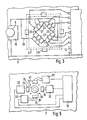
- a section of a circuit board 3 is shown in FIG. 3 at the location of the position difference switch arrangement 17 of a remote control transmitter.
- the circuit board 3 contains an axially symmetrical recess 20, the edges 21 of which are slightly curved into the recess 20.
- a narrower contact element 22 is attached to each edge in the middle, and a wider contact element 23 is attached to the left and right thereof.
- a ball 24 shown in broken lines in the drawing is mounted in the horizontal plate. In this position, the highly conductive surface 25 (FIGS.
- the ball 24 thus forms with the middle contact elements 22 a gravity switch for identifying an approximately horizontal rest position of the remote control transmitter.
- the four corners of the square recess 20 in the circuit board 3 point in the four directions in which the remaining four gravity switches are effective.
- a cover cap 27 is fastened in recesses 26 of the plate 3, which is indicated by dashed lines in FIG. 3 and shown cut open in FIGS. 4a and 4b is.
- the cap 27 contains a stop edge 28 which delimits and optionally guides the ball 20.
- the curved design of the edges 21 of the recess 20 also contributes to better guidance of the ball 24 in the individual directions of action.
- the one contacts of the five gravity switches are connected in the exemplary embodiment shown together with the switch 19 of the remote control transmitter via electrical lines 29; the other contact elements of these gravity switches are individually connected to a direction signal converter 10.
- FIG. 4a the position of the ball 24, the common switching element, is again in a side view
- the five gravity switches, the position difference switch arrangement 17, is shown in the horizontal rest position of the remote control transmitter, in which the main axis 12 of the switch arrangement shown runs parallel to the direction of gravity 13.
- FIG. 4b shows the switch arrangement shown in FIG. 4a in a position of the remote control transmitter which is inclined upwards by the angle a, in which the ball 24 abuts the stop edge 28 of the cover cap 27.
- the angle of inclination a is greater than the trigger angle a0 in which the center of gravity of the ball 24 just penetrates the vertical plane through the points of contact of the ball on the edges 21 of the recess 20 in the plate 3.
- the section of a circuit board 3 of a remote control transmitter shown in FIG. 5 contains a position difference switch arrangement 17, in which a ball 24 is likewise mounted in a recess 30 in the circuit board.
- the circular recess 30 is covered by the ball 24 and shown in dashed lines.
- four voice coils 31 are arranged in a ring shape on the circuit board 3, ie one voice coil in front of and behind and to the right and left next to the cutout 30 in the circuit board 3 of the remote control transmitter in the view of the open encoder housing.
- Each of these voice coils 31 is connected to an associated electrical oscillator 32.
- the oscillators 32 are set so that they generate an electrical oscillation in the rest position of the ball 24, in which it is mounted in the recess 30.
- the vibration breaks off.
- Guide rods 33 arranged on the circuit board ensure that the ball 24 approaches only one voice coil when the remote control transmitter is pivoted, so that the oscillation of only one oscillator is interrupted.
- the oscillators 32 are connected to a directional signal converter 10, which generates an output signal dependent on the inclination of the remote control transmitter for transmission to an electrical device to be operated remotely.
- the ball 24 and the voice coils 31 are protected and secured by a cover cap, not shown in the drawing.
- FIG. 6 schematically shows a position difference switch arrangement of a remote control transmitter which contains a liquid switch 34 as a gravity switch.
- This liquid switch is arranged on the circuit board 3, which is fixed in position in the transmitter housing of a remote control transmitter, and contains a large, plate-shaped center contact 36 on the bottom of the switch housing 35.
- four contact elements are distributed in a ring around the edge of the top of the switch housing 35 37 arranged much smaller area.
- the switch housing contains a non-wetting, electrically conductive liquid 41, in the amount that it covers only one of the contact elements 37 when the printed circuit board 3 is in a vertical position.
- the conductive liquid wets the Contact element 37, which is assigned to the direction of the inclination of the circuit board 3 and thus the direction of the inclination of the remote control transmitter and thus establishes a conductive connection between the center contact 36 and this contact element 37, so that the gravity switch thus formed is closed in an electrically conductive manner.
- the four contact elements 37 of the liquid switch 34 are connected to a directional signal converter 10, which forms a direction-dependent output signal from the signals transmitted via the contacts of the liquid switch, which is transmitted by the remote control transmitter in a transmission signal as a control command remote-controlled electrical device is transmitted.
- Mercury is particularly suitable as the conductive, non-wetting liquid 41 in the switch housing 35, which has a high flow damping because of its inertia and heaviness.
- the switch housing 35 of the liquid switch 34 contains flow damping means, not shown in detail.
- the position difference switch arrangement 17 contains a plurality of acceleration switches instead of gravity switches 7, 8, 9, which for the sake of simplicity are identified by the same reference numerals as the gravity switches in FIGS. 1a to 1c.
- the acceleration switches generate an output signal when the acceleration is above a certain acceleration amount and in a certain acceleration direction for which the acceleration switch is designed.
- acceleration switches 7, 8, 9 By an appropriate arrangement of the acceleration switches 7, 8, 9 with an orientation in the four main directions of movement of the remote control transmitter, namely upwards and downwards and towards the two sides, these accelerators use their output signals to report the pivoting movement state of the remote control transmitter to a directional signal converter 10, which uses these output signals to generate a direction-dependent output signal for transmission as a control command to an electrical device to be remote-controlled.
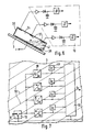
- FIG. 7 schematically shows a position difference switch arrangement 17 of a remote control transmitter, which contains sensors 38 which respond to a certain force or radiation field.
- field lines 39 of such a force or radiation field are shown schematically, the intensity of which the sensors 38 measure in a direction-dependent manner and output a corresponding analog signal Sa at their output.
- the sensors 38 are arranged in four different directions of action, so that they generally output different analog signals Sa during a measurement.
- Analog value memories 40 and a directional signal converter 10 are connected to the output of the sensors 38. The outputs of the analog value memories 40 are also connected to the directional signal converter 10.
- the user of the remote control transmitter first presses the button 6 of the switch 19 of the remote control transmitter, not shown, and carries out the desired pivoting movement of the remote control transmitter when the push button 6 is actuated.
- the analog signals Sa output by the sensors 38 are stored in the analog value memories 40. These then serve the directional signal converter 10 as a reference value for the subsequent pivoting movement.
- the direction signal converter determines the direction of the pivoting movement from the analog values output by the sensors 38 after being stored in the analog value memory 40 and outputs a corresponding direction-dependent output signal Sr at its output, which as a control command to a remote control electrical device is transmitted.
Applications Claiming Priority (2)
| Application Number | Priority Date | Filing Date | Title |
|---|---|---|---|
| DE3840643 | 1988-12-02 | ||
| DE3840643A DE3840643A1 (de) | 1988-12-02 | 1988-12-02 | Fernbedienungsgeber zur abstrahlung von steuerbefehlen |
Publications (2)
| Publication Number | Publication Date |
|---|---|
| EP0373407A1 true EP0373407A1 (fr) | 1990-06-20 |
| EP0373407B1 EP0373407B1 (fr) | 1994-08-03 |
Family
ID=6368327
Family Applications (1)
| Application Number | Title | Priority Date | Filing Date |
|---|---|---|---|
| EP89121799A Expired - Lifetime EP0373407B1 (fr) | 1988-12-02 | 1989-11-25 | Dispositif de commande à distance pour l'émission de commandes |
Country Status (6)
| Country | Link |
|---|---|
| US (1) | US4977404A (fr) |
| EP (1) | EP0373407B1 (fr) |
| JP (1) | JPH06103956B2 (fr) |
| AT (1) | ATE109580T1 (fr) |
| DE (2) | DE3840643A1 (fr) |
| ES (1) | ES2060727T3 (fr) |
Cited By (2)
| Publication number | Priority date | Publication date | Assignee | Title |
|---|---|---|---|---|
| EP0410194A1 (fr) * | 1989-07-25 | 1991-01-30 | Nokia (Deutschland) GmbH | Emetteur de télécommande |
| EP1933282A3 (fr) * | 2006-12-12 | 2009-07-15 | Honeywell International Inc. | Commande sans fil de système de sécurité avec porte-clé à clé |
Families Citing this family (27)
| Publication number | Priority date | Publication date | Assignee | Title |
|---|---|---|---|---|
| JPH04242398A (ja) * | 1991-01-16 | 1992-08-31 | Sharp Corp | 遠隔制御用送信機 |
| JPH0641291U (ja) * | 1992-07-28 | 1994-05-31 | 節子 大塚 | 多機能テレビ用リモートコントローラ |
| DE4237867A1 (de) * | 1992-11-10 | 1994-05-11 | Mueller Alexander | Sender zur kabellosen Übermittlung von Steuerbefehlen |
| EP0619567A1 (fr) * | 1993-04-05 | 1994-10-12 | Whirlpool Corporation | Méthode et dispositif pour la mesure d'une condition de température excessive pour un appareil électroménager |
| DE19855605A1 (de) * | 1998-12-02 | 2000-06-15 | Siemens Ag | Handsender zum Fernsteuern von Betriebsfunktionen, insbesondere von Kraftfahrzeugfunktionen |
| US6750801B2 (en) * | 2000-12-29 | 2004-06-15 | Bellsouth Intellectual Property Corporation | Remote control device with directional mode indicator |
| US20030016417A1 (en) * | 2001-07-17 | 2003-01-23 | Cruise Lee | Wireless pointing and remote-controlling device for briefing |
| JP2003325972A (ja) | 2002-05-17 | 2003-11-18 | Nintendo Co Ltd | 傾き操作に関連して音と画像を変化させるゲーム装置およびそのゲームプログラム |
| US8570378B2 (en) | 2002-07-27 | 2013-10-29 | Sony Computer Entertainment Inc. | Method and apparatus for tracking three-dimensional movements of an object using a depth sensing camera |
| US9174119B2 (en) | 2002-07-27 | 2015-11-03 | Sony Computer Entertainement America, LLC | Controller for providing inputs to control execution of a program when inputs are combined |
| US9393487B2 (en) | 2002-07-27 | 2016-07-19 | Sony Interactive Entertainment Inc. | Method for mapping movements of a hand-held controller to game commands |
| US7918733B2 (en) | 2002-07-27 | 2011-04-05 | Sony Computer Entertainment America Inc. | Multi-input game control mixer |
| US8313380B2 (en) * | 2002-07-27 | 2012-11-20 | Sony Computer Entertainment America Llc | Scheme for translating movements of a hand-held controller into inputs for a system |
| US7854655B2 (en) * | 2002-07-27 | 2010-12-21 | Sony Computer Entertainment America Inc. | Obtaining input for controlling execution of a game program |
| US7850526B2 (en) | 2002-07-27 | 2010-12-14 | Sony Computer Entertainment America Inc. | System for tracking user manipulations within an environment |
| US7183897B2 (en) * | 2004-11-19 | 2007-02-27 | Lear Corporation | Key fob deactivation system and method |
| ITMI20051731A1 (it) * | 2005-09-19 | 2007-03-20 | Ec Elettronica S R L | Dispositivo di telecomando sensibile alla posizione per il controllo di apparecchiature e simili |
| US8781151B2 (en) | 2006-09-28 | 2014-07-15 | Sony Computer Entertainment Inc. | Object detection using video input combined with tilt angle information |
| USRE48417E1 (en) | 2006-09-28 | 2021-02-02 | Sony Interactive Entertainment Inc. | Object direction using video input combined with tilt angle information |
| US8310656B2 (en) | 2006-09-28 | 2012-11-13 | Sony Computer Entertainment America Llc | Mapping movements of a hand-held controller to the two-dimensional image plane of a display screen |
| US8918543B2 (en) * | 2006-11-06 | 2014-12-23 | International Business Machines Corporation | Changing device functionality using environment conditions |
| DE102007055465A1 (de) * | 2007-11-13 | 2009-05-20 | Trumpf Medizin Systeme Gmbh | Fernbedienung für eine Vorrichtung zur Lagerung eines Patienten |
| DE102008034497A1 (de) * | 2008-04-30 | 2009-11-05 | Hörmann KG Antriebstechnik | Torantriebs-Fernsteuerungssender sowie damit versehenes Torantriebsystem |
| CN101625938B (zh) * | 2008-07-07 | 2012-01-25 | 黄国恩 | 一种电路板感应模块 |
| US20100052931A1 (en) * | 2008-08-26 | 2010-03-04 | Gm Global Technology Operations, Inc. | Gesture control key fob |
| DE102012010564A1 (de) | 2012-05-26 | 2013-11-28 | Audi Ag | Fernbedienungsvorrichtung für einen Kraftwagen sowie Verfahren zum Betreiben einer solchenFernbedienungsvorrichtung |
| US10147564B2 (en) | 2013-02-07 | 2018-12-04 | Universal Electronics Inc. | System and methods for providing orientation compensation in pointing devices |
Citations (4)
| Publication number | Priority date | Publication date | Assignee | Title |
|---|---|---|---|---|
| FR1401364A (fr) * | 1964-04-22 | 1965-06-04 | Cogerel | Récepteur à fréquences préréglées commutables par gravité |
| DE2805896A1 (de) * | 1978-02-13 | 1979-08-16 | Hoermann Kg Antrieb Steuertec | Handsender fuer zwei unterschiedliche signale |
| FR2510900A1 (fr) * | 1981-08-07 | 1983-02-11 | Thomson Brandt | Manette de jeu |
| GB2146813A (en) * | 1983-09-06 | 1985-04-24 | Thorn Emi Ferguson | Control Unit |
Family Cites Families (5)
| Publication number | Priority date | Publication date | Assignee | Title |
|---|---|---|---|---|
| US4216467A (en) * | 1977-12-22 | 1980-08-05 | Westinghouse Electric Corp. | Hand controller |
| JPS5988701U (ja) * | 1982-11-30 | 1984-06-15 | 株式会社島津製作所 | 位置指示器 |
| JPS61134183U (fr) * | 1986-02-01 | 1986-08-21 | ||
| JPS63158072U (fr) * | 1987-04-01 | 1988-10-17 | ||
| US4829285A (en) * | 1987-06-11 | 1989-05-09 | Marc I. Brand | In-home emergency assist device |
-
1988
- 1988-12-02 DE DE3840643A patent/DE3840643A1/de not_active Withdrawn
-
1989
- 1989-11-25 DE DE58908145T patent/DE58908145D1/de not_active Expired - Fee Related
- 1989-11-25 AT AT89121799T patent/ATE109580T1/de not_active IP Right Cessation
- 1989-11-25 EP EP89121799A patent/EP0373407B1/fr not_active Expired - Lifetime
- 1989-11-25 ES ES89121799T patent/ES2060727T3/es not_active Expired - Lifetime
- 1989-11-28 US US07/442,127 patent/US4977404A/en not_active Expired - Lifetime
- 1989-12-01 JP JP1313120A patent/JPH06103956B2/ja not_active Expired - Fee Related
Patent Citations (4)
| Publication number | Priority date | Publication date | Assignee | Title |
|---|---|---|---|---|
| FR1401364A (fr) * | 1964-04-22 | 1965-06-04 | Cogerel | Récepteur à fréquences préréglées commutables par gravité |
| DE2805896A1 (de) * | 1978-02-13 | 1979-08-16 | Hoermann Kg Antrieb Steuertec | Handsender fuer zwei unterschiedliche signale |
| FR2510900A1 (fr) * | 1981-08-07 | 1983-02-11 | Thomson Brandt | Manette de jeu |
| GB2146813A (en) * | 1983-09-06 | 1985-04-24 | Thorn Emi Ferguson | Control Unit |
Non-Patent Citations (1)
| Title |
|---|
| IBM TECHNICAL DISCLOSURE BULLETIN, Band 29, Nr. 10, März 1987, Seiten 4269,4270: "Tilt detection unit" * |
Cited By (4)
| Publication number | Priority date | Publication date | Assignee | Title |
|---|---|---|---|---|
| EP0410194A1 (fr) * | 1989-07-25 | 1991-01-30 | Nokia (Deutschland) GmbH | Emetteur de télécommande |
| EP1933282A3 (fr) * | 2006-12-12 | 2009-07-15 | Honeywell International Inc. | Commande sans fil de système de sécurité avec porte-clé à clé |
| US7843312B2 (en) | 2006-12-12 | 2010-11-30 | Honeywell International Inc. | Wireless control of security system with key-operated key fob |
| CN101200985B (zh) * | 2006-12-12 | 2013-04-24 | 霍尼韦尔国际公司 | 具有钥匙操作的钥匙袋的安全系统的无线控制装置 |
Also Published As
| Publication number | Publication date |
|---|---|
| EP0373407B1 (fr) | 1994-08-03 |
| ATE109580T1 (de) | 1994-08-15 |
| JPH06103956B2 (ja) | 1994-12-14 |
| DE58908145D1 (de) | 1994-09-08 |
| JPH02244898A (ja) | 1990-09-28 |
| ES2060727T3 (es) | 1994-12-01 |
| US4977404A (en) | 1990-12-11 |
| DE3840643A1 (de) | 1990-06-07 |
Similar Documents
| Publication | Publication Date | Title |
|---|---|---|
| EP0373407B1 (fr) | Dispositif de commande à distance pour l'émission de commandes | |
| EP0234193B1 (fr) | Agencement d'interrupteur | |
| DE69636368T2 (de) | Auslöserbetätigte elektronische vorrichtung | |
| EP0740844B1 (fr) | Interrupteur a plusieurs etages | |
| EP0410194A1 (fr) | Emetteur de télécommande | |
| EP0185912A1 (fr) | Appareil de commande à distance des récepteurs de radio et appareillages similaires | |
| EP0840909A1 (fr) | Dispositif de commande et de programmation | |
| DE3705492A1 (de) | X-y-richtungseingabevorrichtung | |
| DE3222237A1 (de) | Kippschalter | |
| DE3005210A1 (de) | Schalter | |
| DE3835970A1 (de) | Mehrstufige druckknopfvorrichtung | |
| DE7103467U (de) | Anreihbarer Drucktastenschalter | |
| DE3906585A1 (de) | Fernbedieneinheit | |
| EP1519623B1 (fr) | Télécommande pour des prothèses auditives | |
| DE2733337A1 (de) | Drucktastenschalter | |
| DE3530971A1 (de) | Bedienanordnung | |
| DE2827075C2 (de) | Handapparat für die Bedienung elektronisch steuerbarer Geräte | |
| DE4306640A1 (de) | Navigationseinrichtung | |
| DE2625726B2 (de) | Elektronische Kleinuhr | |
| DE4107085C2 (de) | Koordinaten-Eingabevorrichtung | |
| DE3437456C1 (de) | Steuervorrichtung fuer Computer | |
| DE3412965A1 (de) | Elektrisches bauteil | |
| DE2854773A1 (de) | Zeitmess- und anzeigevorrichtung | |
| DE8215903U1 (de) | Transportabler Funkfernsteuersender | |
| DE2558666C3 (fr) |
Legal Events
| Date | Code | Title | Description |
|---|---|---|---|
| PUAI | Public reference made under article 153(3) epc to a published international application that has entered the european phase |
Free format text: ORIGINAL CODE: 0009012 |
|
| AK | Designated contracting states |
Kind code of ref document: A1 Designated state(s): AT DE ES FR GB IT NL |
|
| 17P | Request for examination filed |
Effective date: 19901119 |
|
| RAP1 | Party data changed (applicant data changed or rights of an application transferred) |
Owner name: NOKIA (DEUTSCHLAND) GMBH |
|
| 17Q | First examination report despatched |
Effective date: 19921209 |
|
| GRAA | (expected) grant |
Free format text: ORIGINAL CODE: 0009210 |
|
| AK | Designated contracting states |
Kind code of ref document: B1 Designated state(s): AT DE ES FR GB IT NL |
|
| REF | Corresponds to: |
Ref document number: 109580 Country of ref document: AT Date of ref document: 19940815 Kind code of ref document: T |
|
| ITF | It: translation for a ep patent filed |
Owner name: JACOBACCI CASETTA & PERANI S.P.A. |
|
| REF | Corresponds to: |
Ref document number: 58908145 Country of ref document: DE Date of ref document: 19940908 |
|
| GBT | Gb: translation of ep patent filed (gb section 77(6)(a)/1977) |
Effective date: 19940822 |
|
| ET | Fr: translation filed | ||
| REG | Reference to a national code |
Ref country code: ES Ref legal event code: FG2A Ref document number: 2060727 Country of ref document: ES Kind code of ref document: T3 |
|
| PLBE | No opposition filed within time limit |
Free format text: ORIGINAL CODE: 0009261 |
|
| STAA | Information on the status of an ep patent application or granted ep patent |
Free format text: STATUS: NO OPPOSITION FILED WITHIN TIME LIMIT |
|
| 26N | No opposition filed | ||
| PGFP | Annual fee paid to national office [announced via postgrant information from national office to epo] |
Ref country code: AT Payment date: 20011113 Year of fee payment: 13 |
|
| PGFP | Annual fee paid to national office [announced via postgrant information from national office to epo] |
Ref country code: ES Payment date: 20011122 Year of fee payment: 13 |
|
| REG | Reference to a national code |
Ref country code: GB Ref legal event code: IF02 |
|
| PGFP | Annual fee paid to national office [announced via postgrant information from national office to epo] |
Ref country code: FR Payment date: 20021108 Year of fee payment: 14 |
|
| PGFP | Annual fee paid to national office [announced via postgrant information from national office to epo] |
Ref country code: GB Payment date: 20021120 Year of fee payment: 14 |
|
| PG25 | Lapsed in a contracting state [announced via postgrant information from national office to epo] |
Ref country code: AT Free format text: LAPSE BECAUSE OF NON-PAYMENT OF DUE FEES Effective date: 20021125 |
|
| PG25 | Lapsed in a contracting state [announced via postgrant information from national office to epo] |
Ref country code: ES Free format text: LAPSE BECAUSE OF NON-PAYMENT OF DUE FEES Effective date: 20021126 |
|
| PGFP | Annual fee paid to national office [announced via postgrant information from national office to epo] |
Ref country code: DE Payment date: 20021128 Year of fee payment: 14 |
|
| PGFP | Annual fee paid to national office [announced via postgrant information from national office to epo] |
Ref country code: NL Payment date: 20021129 Year of fee payment: 14 |
|
| PG25 | Lapsed in a contracting state [announced via postgrant information from national office to epo] |
Ref country code: GB Free format text: LAPSE BECAUSE OF NON-PAYMENT OF DUE FEES Effective date: 20031125 |
|
| REG | Reference to a national code |
Ref country code: ES Ref legal event code: FD2A Effective date: 20031213 |
|
| PG25 | Lapsed in a contracting state [announced via postgrant information from national office to epo] |
Ref country code: NL Free format text: LAPSE BECAUSE OF NON-PAYMENT OF DUE FEES Effective date: 20040601 |
|
| PG25 | Lapsed in a contracting state [announced via postgrant information from national office to epo] |
Ref country code: DE Free format text: LAPSE BECAUSE OF NON-PAYMENT OF DUE FEES Effective date: 20040602 |
|
| GBPC | Gb: european patent ceased through non-payment of renewal fee |
Effective date: 20031125 |
|
| PG25 | Lapsed in a contracting state [announced via postgrant information from national office to epo] |
Ref country code: FR Free format text: LAPSE BECAUSE OF NON-PAYMENT OF DUE FEES Effective date: 20040730 |
|
| NLV4 | Nl: lapsed or anulled due to non-payment of the annual fee |
Effective date: 20040601 |
|
| REG | Reference to a national code |
Ref country code: FR Ref legal event code: ST |
|
| PG25 | Lapsed in a contracting state [announced via postgrant information from national office to epo] |
Ref country code: IT Free format text: LAPSE BECAUSE OF NON-PAYMENT OF DUE FEES Effective date: 20051125 |