EP0372223B1 - Sinterwerkstoff auf Kupferbasis, dessen Verwendung sowie Verfahren zur Herstellung von Formteilen aus dem Sinterwerkstoff - Google Patents
Sinterwerkstoff auf Kupferbasis, dessen Verwendung sowie Verfahren zur Herstellung von Formteilen aus dem Sinterwerkstoff Download PDFInfo
- Publication number
- EP0372223B1 EP0372223B1 EP89120242A EP89120242A EP0372223B1 EP 0372223 B1 EP0372223 B1 EP 0372223B1 EP 89120242 A EP89120242 A EP 89120242A EP 89120242 A EP89120242 A EP 89120242A EP 0372223 B1 EP0372223 B1 EP 0372223B1
- Authority
- EP
- European Patent Office
- Prior art keywords
- sintered material
- valve
- weight
- metal powder
- percent
- Prior art date
- Legal status (The legal status is an assumption and is not a legal conclusion. Google has not performed a legal analysis and makes no representation as to the accuracy of the status listed.)
- Expired - Lifetime
Links
Images

Classifications
-
- B—PERFORMING OPERATIONS; TRANSPORTING
- B22—CASTING; POWDER METALLURGY
- B22F—WORKING METALLIC POWDER; MANUFACTURE OF ARTICLES FROM METALLIC POWDER; MAKING METALLIC POWDER; APPARATUS OR DEVICES SPECIALLY ADAPTED FOR METALLIC POWDER
- B22F1/00—Metallic powder; Treatment of metallic powder, e.g. to facilitate working or to improve properties
- B22F1/05—Metallic powder characterised by the size or surface area of the particles
-
- F—MECHANICAL ENGINEERING; LIGHTING; HEATING; WEAPONS; BLASTING
- F02—COMBUSTION ENGINES; HOT-GAS OR COMBUSTION-PRODUCT ENGINE PLANTS
- F02F—CYLINDERS, PISTONS OR CASINGS, FOR COMBUSTION ENGINES; ARRANGEMENTS OF SEALINGS IN COMBUSTION ENGINES
- F02F7/00—Casings, e.g. crankcases
- F02F7/0085—Materials for constructing engines or their parts
- F02F7/0087—Ceramic materials
-
- B—PERFORMING OPERATIONS; TRANSPORTING
- B22—CASTING; POWDER METALLURGY
- B22F—WORKING METALLIC POWDER; MANUFACTURE OF ARTICLES FROM METALLIC POWDER; MAKING METALLIC POWDER; APPARATUS OR DEVICES SPECIALLY ADAPTED FOR METALLIC POWDER
- B22F3/00—Manufacture of workpieces or articles from metallic powder characterised by the manner of compacting or sintering; Apparatus specially adapted therefor ; Presses and furnaces
- B22F3/10—Sintering only
-
- C—CHEMISTRY; METALLURGY
- C22—METALLURGY; FERROUS OR NON-FERROUS ALLOYS; TREATMENT OF ALLOYS OR NON-FERROUS METALS
- C22C—ALLOYS
- C22C1/00—Making non-ferrous alloys
- C22C1/04—Making non-ferrous alloys by powder metallurgy
-
- C—CHEMISTRY; METALLURGY
- C22—METALLURGY; FERROUS OR NON-FERROUS ALLOYS; TREATMENT OF ALLOYS OR NON-FERROUS METALS
- C22C—ALLOYS
- C22C1/00—Making non-ferrous alloys
- C22C1/04—Making non-ferrous alloys by powder metallurgy
- C22C1/0425—Copper-based alloys
-
- C—CHEMISTRY; METALLURGY
- C22—METALLURGY; FERROUS OR NON-FERROUS ALLOYS; TREATMENT OF ALLOYS OR NON-FERROUS METALS
- C22C—ALLOYS
- C22C32/00—Non-ferrous alloys containing at least 5% by weight but less than 50% by weight of oxides, carbides, borides, nitrides, silicides or other metal compounds, e.g. oxynitrides, sulfides, whether added as such or formed in situ
- C22C32/0047—Non-ferrous alloys containing at least 5% by weight but less than 50% by weight of oxides, carbides, borides, nitrides, silicides or other metal compounds, e.g. oxynitrides, sulfides, whether added as such or formed in situ with carbides, nitrides, borides or silicides as the main non-metallic constituents
- C22C32/0052—Non-ferrous alloys containing at least 5% by weight but less than 50% by weight of oxides, carbides, borides, nitrides, silicides or other metal compounds, e.g. oxynitrides, sulfides, whether added as such or formed in situ with carbides, nitrides, borides or silicides as the main non-metallic constituents only carbides
-
- F—MECHANICAL ENGINEERING; LIGHTING; HEATING; WEAPONS; BLASTING
- F01—MACHINES OR ENGINES IN GENERAL; ENGINE PLANTS IN GENERAL; STEAM ENGINES
- F01L—CYCLICALLY OPERATING VALVES FOR MACHINES OR ENGINES
- F01L3/00—Lift-valve, i.e. cut-off apparatus with closure members having at least a component of their opening and closing motion perpendicular to the closing faces; Parts or accessories thereof
- F01L3/22—Valve-seats not provided for in preceding subgroups of this group; Fixing of valve-seats
-
- B—PERFORMING OPERATIONS; TRANSPORTING
- B22—CASTING; POWDER METALLURGY
- B22F—WORKING METALLIC POWDER; MANUFACTURE OF ARTICLES FROM METALLIC POWDER; MAKING METALLIC POWDER; APPARATUS OR DEVICES SPECIALLY ADAPTED FOR METALLIC POWDER
- B22F2301/00—Metallic composition of the powder or its coating
- B22F2301/10—Copper
-
- B—PERFORMING OPERATIONS; TRANSPORTING
- B22—CASTING; POWDER METALLURGY
- B22F—WORKING METALLIC POWDER; MANUFACTURE OF ARTICLES FROM METALLIC POWDER; MAKING METALLIC POWDER; APPARATUS OR DEVICES SPECIALLY ADAPTED FOR METALLIC POWDER
- B22F2301/00—Metallic composition of the powder or its coating
- B22F2301/15—Nickel or cobalt
-
- B—PERFORMING OPERATIONS; TRANSPORTING
- B22—CASTING; POWDER METALLURGY
- B22F—WORKING METALLIC POWDER; MANUFACTURE OF ARTICLES FROM METALLIC POWDER; MAKING METALLIC POWDER; APPARATUS OR DEVICES SPECIALLY ADAPTED FOR METALLIC POWDER
- B22F2301/00—Metallic composition of the powder or its coating
- B22F2301/20—Refractory metals
-
- B—PERFORMING OPERATIONS; TRANSPORTING
- B22—CASTING; POWDER METALLURGY
- B22F—WORKING METALLIC POWDER; MANUFACTURE OF ARTICLES FROM METALLIC POWDER; MAKING METALLIC POWDER; APPARATUS OR DEVICES SPECIALLY ADAPTED FOR METALLIC POWDER
- B22F2998/00—Supplementary information concerning processes or compositions relating to powder metallurgy
- B22F2998/10—Processes characterised by the sequence of their steps
-
- F—MECHANICAL ENGINEERING; LIGHTING; HEATING; WEAPONS; BLASTING
- F02—COMBUSTION ENGINES; HOT-GAS OR COMBUSTION-PRODUCT ENGINE PLANTS
- F02B—INTERNAL-COMBUSTION PISTON ENGINES; COMBUSTION ENGINES IN GENERAL
- F02B1/00—Engines characterised by fuel-air mixture compression
- F02B1/02—Engines characterised by fuel-air mixture compression with positive ignition
- F02B1/04—Engines characterised by fuel-air mixture compression with positive ignition with fuel-air mixture admission into cylinder
-
- F—MECHANICAL ENGINEERING; LIGHTING; HEATING; WEAPONS; BLASTING
- F02—COMBUSTION ENGINES; HOT-GAS OR COMBUSTION-PRODUCT ENGINE PLANTS
- F02B—INTERNAL-COMBUSTION PISTON ENGINES; COMBUSTION ENGINES IN GENERAL
- F02B3/00—Engines characterised by air compression and subsequent fuel addition
- F02B3/06—Engines characterised by air compression and subsequent fuel addition with compression ignition
Definitions
- the invention relates to a sintered material which is resistant to heat and mechanical stress, in particular shock and friction, and which is produced from a base metal powder for the production of molded parts.
- the invention relates to the use of the sintered material mentioned at the outset and a method for producing molded parts from the sintered material.
- Such a sintered material is used, for example, to produce molded parts for machines which are exposed to hot gases or gas mixtures such as combustion gases. This applies to parts of piston machines, such as valve seat rings.
- a sintered material which consists of an iron-based material, the carbon and lead and other alloy components are added.
- This sintered material is said to have an increased thermal conductivity compared to previously known ones.
- the heat and erosion resistance of the valve seat rings made from the sintered material should also be increased.
- the increase in thermal conductivity and erosion resistance are, however, set relatively low limits by the fact that the base material is an iron base material.
- JP-A-50 153 706 Another sintered material for the production of valve seat rings is known from JP-A-50 153 706.
- This sintered material is composed on the one hand of an iron base mixture as a hard phase and on the other hand on a base metal powder, which consists of a mixture of copper and cobalt powder.
- the thermal conductivity is also limited due to the high proportion of the iron-based material (up to 60 percent by weight). With this sintered material, too, undesirable deposits and incrustations can occur, particularly in the region of the fillet of the valve disk.
- Another disadvantage is that pure cobalt powder, which is considered to be carcinogenic, is used to produce the sintered material.
- valve seat ring for a reciprocating piston internal combustion engine is known from DE-OS 35 28 526.
- the valve seat is formed from two rings, of which the inner valve ring arranged on the seat surface of the valve consists of a heat-resistant, non-powder-metallurgically manufactured material of high hardness, while the outer seat ring arranged in the seat is made of a highly thermally conductive, likewise non-powder-metallurgically manufactured material is. It should be noted, however, that the greatest heat occurs in the area of the seat of the valve and thus in the inner valve ring. From there it should first be discharged through the inner valve ring and then through the outer seat ring. It is suitable for this the heat-resistant material of high hardness provided for the inner valve ring is only limited, since it only has a normal thermal conductivity.
- the invention has for its object to provide a sintered material, the resistance to heat and mechanical stress, such as shock and friction, is significantly greater than that of known sintered materials.
- the invention is based on the particular object of creating a sintered material which is suitable for the production of valve seat rings.
- the sintered material is composed of a base metal powder and a hard phase
- the base metal powder consisting of a copper content of 70 to 100 weight percent and an alloy content of 0 to 30 weight percent chromium and / or iron and / or manganese and / or nickel and / or tungsten and / or carbon
- the hard phase consists of a high-alloy additional metal powder based on cobalt, that is composed of chromium and / or nickel and / or tungsten and / or carbon, the rest cobalt, the proportion the hard phase in the sintered material is at most 30 percent by weight.
- This sintered material like well-known sintered materials, also has the production-related impurities.
- the sintered material according to the invention has a much higher thermal conductivity.
- mechanical stress such as shock and / or friction
- oxides are formed that develop a lubricating effect. This results in the resistance of the sintered material to mechanical stress, for example in the event of direct contact between metal and metal without the addition of lubricant.
- One or more oxides form a lubricating layer that reliably prevents the sintered material from welding for a short time and in a localized manner when it comes into direct contact with another metallic material.
- the sintered material according to the invention thus has the property of self-lubrication that spontaneously renews itself at any time.
- the copper-based material which has a very high thermal conductivity compared to other metallic materials and also forms oxides with sufficient separating and lubricating effects.
- alloy components which also form oxides when heated.
- the heat conditions can correspond to those prevailing in the combustion chambers of internal combustion engines, in particular internal combustion engines.
- the sintered material according to the invention then has a particularly low coefficient of friction. Although it is a relatively soft sintered material, the sintered material has considerable wear resistance due to its other properties. As a result, it can withstand higher mechanical stresses with higher heat more sustainably than known sintered materials based on iron, which have a higher hardness.
- a preferred embodiment of the invention is characterized in that the copper content is 95 to 100 weight percent and the alloy content is 5 to 0 weight percent.
- the proportion of impurities caused by production can amount to at most 0.5 percent by weight, the maximum particle size approximately 150 ⁇ m and the average particle size approximately 45 to 60 ⁇ m.
- the proportion of the hard phase can also be reduced so that it is at most 10 percent by weight.
- the proportion of the hard phase of at most 30 or 10 percent by weight relates to the sum of base metal powder and additional metal powder. It follows that the proportion of copper and alloy in the base metal powder is correspondingly smaller make up the sum of base metal powder and additional metal powder. If, according to the invention, powder metallurgical processes are used, structures can be produced in which wear-reducing structural components are embedded in a highly thermally conductive base compound.
- the composition of the hard phase in percentages by weight is: 24 to 28 chromium, 21 to 25 nickel, 10 to 14 tungsten, 1.5 to 2.0 carbon, the rest cobalt.
- the hard phase can also have the following composition: 28 to 32 chromium, 5 to 10 tungsten, 0.3 to 2.5 carbon, the rest cobalt.
- the base metal powder can be a pure, unalloyed copper powder. The base is then alloyed during the sintering by diffusion with cobalt.
- the sintered material as such and its various configurations can be used according to the invention for the production of heat and / or wear-resistant molded parts which are exposed to hot gases or gas mixtures, for example combustion gases.
- these can be sealing, guiding, bearing or valve elements.
- machines such as piston machines and their additional units.
- Use in turbochargers or exhaust gas and exhaust gas recirculation systems is also possible.
- valve seat rings for internal combustion engines are used.
- Valve seat rings made from the sintered material or its various designs are able to dissipate the heat developed by combustion well. This offers the possibility that the combustion can take place at higher temperatures than before. This increases the efficiency of an internal combustion engine.
- the heat is dissipated from the extremely hot seat of the valve via the valve seat ring. This makes it possible to manufacture the valve from a less heat-resistant and therefore cheaper material than known valves. Alternatively, the possibility is given to realize higher combustion temperatures when using known materials for the valve without the valve being damaged.
- known valve seat rings are made from a material of high hardness to reduce wear. So that the known valve is in turn not subject to excessive wear in the contact area, the known hard valve seat ring is paired with a valve which is lavishly armored in the area of the known valve seat with a highly hard protective layer.
- Known heat-resistant materials of high hardness have a low thermal conductivity and represent a barrier to the heat flow from the valve to the valve seat ring.
- valve seat ring according to the invention.
- the sintered material according to the invention is relatively soft, it is Wear resistance of the valve ring made from it is higher. The reason for this is also that the layer formed by the oxides on the valve seat ring develops a separating and lubricating property.
- the sintered material is used to produce valve seats for internal combustion engines with a seat ring to be arranged in the seat and a valve ring to be arranged on the seat surface of the valve
- the valve ring to be arranged on the seat surface of the valve must in any case consist of the sintered material according to the invention.
- This preferred solution is based on the knowledge that the particular heat of the valve can best be dissipated when at least the valve ring arranged on the seat surface of the valve has a high thermal conductivity. In contrast, heat dissipation from the valve would only be possible to a lesser extent if the seat ring to be arranged in the seat had a higher thermal conductivity than the valve ring to be arranged on the seat surface of the valve.
- any of the configurations of the sintered material described above can be used for the production of valve seat rings.
- a sintered material according to the invention In addition to the lubricant, the metal alloy as basic powder is mixed with the high-alloy, metallic additional powder as a hard phase, the mixture is pressed into a shaped body and sintered at about 1000 ° C in a protective gas atmosphere.
- the lubricant is a known pressing aid. This is mixed with the metal powders or metal powder mixtures to improve the compressibility in contents of 0.5 to 1 percent by weight. Before the actual sintering process, the lubricant is decomposed and expelled without residue at temperatures of around 400 ° C. After sintering, the lubricant is no longer detectable in the sintered material. Therefore, the type and amount of the lubricant added has no influence on the property of the sintered material. For example, zinc stearate is used as a lubricant.
- the sintered material according to the invention can be used to produce structures in which more or less finely divided wear-reducing structural components are embedded in a highly heat-conductive base material made of the alloy.
- the use of powder metallurgical processes for the production of molded parts, especially valve seat rings, not only opens up the possibility of increasing the wear resistance of the parts. It also offers the advantage of a particularly cost-effective production, since in this way it is possible to largely pre-form the ring blank as inexpensively as possible, which then requires little or no post-processing.
- the pressing can be carried out using a coaxial pressing technique and, if necessary, the molded parts can be calibrated after sintering.
- valve seat rings according to the invention leads to the described higher heat dissipation from the valve. As a result, the valve is less gets hot. As a result, there are no deposits in the fillet of the inlet valve that must be determined when using known valve seat rings. Deposits there are the result of premature, uncontrolled combustion of the gasoline-air mixture in the area of the fillet of the valve disk, which is very hot due to heat build-up.
- the use of a valve seat ring according to the invention avoids such coking with undesirable deposits. The temperature of the valve is then below the minimum temperature required for coking to occur.
- wear-reducing structural components namely a hard phase 11
- wear-reducing structural components are more or less finely divided into a base material, namely a copper-based material 12, embedded.
- the hard phase 11 preferably has one of the compositions described above.
- the proportion of hard phase 11 is at most 30 percent by weight, while that of copper-based material 12 is at least 70 percent by face.
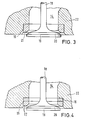
- FIG 3 shows a cylinder head 22 of an internal combustion engine, in which a channel 14 is located.
- the channel 14 has a seat 15 in its lower region. Only a single valve seat ring 21, which consists of the sintered material according to the invention, is arranged in the seat 15.
- a valve 18 is in the open position shown with its seat 20 formed on a valve plate 19 at a distance from the valve seat ring 21.
- Fig. 4 shows a partial section through the cylinder head 22 of an internal combustion engine.
- a seat ring 16 is arranged in the seat 15 and is connected to a valve ring 17. Both the seat ring 16 and the valve ring 17 consist of the sintered material according to the invention.
- the properties of the sintered material according to the invention and its use, preferably for valve seat rings, enable use under high loads. This can occur, for example, on intake valves of diesel engines with turbocharging or on exhaust valves of gasoline engines when using unleaded fuel.
- the required service life of the valves can be achieved without it being necessary to particularly armor the valve plate in the seat. The wear on the valve seat ring and on the associated valve plate is even reduced.
Landscapes
- Engineering & Computer Science (AREA)
- Chemical & Material Sciences (AREA)
- Mechanical Engineering (AREA)
- Materials Engineering (AREA)
- Metallurgy (AREA)
- Organic Chemistry (AREA)
- General Engineering & Computer Science (AREA)
- Ceramic Engineering (AREA)
- Combustion & Propulsion (AREA)
- Manufacturing & Machinery (AREA)
- Powder Metallurgy (AREA)
- Conductive Materials (AREA)
- High-Tension Arc-Extinguishing Switches Without Spraying Means (AREA)
- Manufacture And Refinement Of Metals (AREA)
Description
- Die Erfindung bezieht sich auf einen gegen Wärme und mechanische Beanspruchung, insbesondere Stoß und Reibung, beständigen, aus einem Grundmetallpulver hergestellten Sinterwerkstoff zur Herstellung von Formteilen. Außerdem betrifft die Erfindung die Verwendung des eingangs genannten Sinterwerkstoffes sowie ein Verfahren zur Herstellung von Formteilen aus dem Sinterwerkstoff.
- Aus einem derartigen Sinterwerkstoff werden beispielsweise Formteile für Maschinen hergestellt, die heißen Gasen oder Gasgemischen, wie Verbrennungsgasen, ausgesetzt sind. Dies trifft für Teile von Kolbenmaschinen zu, beispielsweise Ventilsitzringe.
- Aus der DE-PS 21 14 160 ist ein Sinterwerkstoff bekannt, der aus einem Eisenbasiswerkstoff besteht, dem Kohlenstoff und Blei sowie andere Legierungsbestandteile zugesetzt sind. Dieser Sinterwerkstoff soll gegenüber vorbekannten eine erhöhte Wärmeleitfähigkeit besitzen. Warm- und Erosionsfestigkeit der aus dem Sinterwerkstoff hergestellten Ventilsitzringe sollen ebenfalls erhöht sein. Der Erhöhung der Wärmeleitfähigkeit sowie der Erosionsfestigkeit sind aber dadurch verhältnismäßig niedrige Grenzen gesetzt, daß der Basiswerkstoff ein Eisenbasiswerkstoff ist.
- Ein anderer Sinterwerkstoff zur Fertigung von Ventilsitzringen ist aus der JP-A-50 153 706 bekannt. Dieser Sinterwerkstoff setzt sich zum einen aus einer Eisenbasismischung als Hartphase und zum anderen auf einem Grundmetallpulver zusammen, das aus einer Mischung aus Kupfer- und Kobaltpulver besteht. Der Sinterwerkstoff weist zwar eine verbesserte Wärme- und Abriebfestigkeit bei höheren Temperaturen auf, jedoch sind auch hier wegen des hohen Anteils des Eisenbasiswerkstoffs (bis zu 60 Gewichtsprozenten) der Wärmeleitfähigkeit Grenzen gesetzt. Auch bei diesem Sinterwerkstoff kann es daher zu unerwünschten Ablagerungen und Verkrustungen insbesondere im Bereich der Hohlkehle des Ventiltellers kommen. Ferner besteht ein Nachteil darin, daß zur Herstellung des Sinterwerkstoffs reines Kobaltpulver verwendet wird, das als krebserregend gilt.
- Ein Ventilsitzring für eine Hubkolben-Brennkraftmaschine ist aus der DE-OS 35 28 526 bekannt. Dort ist der Ventilsitz aus zwei Ringen gebildet, von denen der an der Sitzfläche des Ventils angeordnete innere Ventilring aus einem warmfesten, nicht pulvermetallurgisch hergestellten Werkstoff hoher Härte besteht, während der im Sitz angeordnete äußere Sitzring aus einem gut wärmeleitfähigen, ebenfalls nicht pulvermetallurgisch hergestellten Werkstoff gefertigt ist. Es ist aber zu beachten, daß die größte Wärme im Bereich der Sitzfläche des Ventils und damit den inneren Ventilringes auftritt. Von dort soll sie zunächst durch den inneren Ventilring und dann durch den äußeren Sitzring abgeleitet werden. Hierfür eignet sich der für den inneren Ventilring vorgesehene warmfeste Werkstoff hoher Häre nur begrenzt, da er lediglich eine übliche Wärmeleitfähigkeit besitzt.
- Der Erfindung liegt die Aufgabe zugrunde, einen Sinterwerkstoff zu schaffen, dessen Beständigkeit gegen Wärme und mechanische Beanspruchung, wie Stoß und Reibung, wesentlich größer ist als diejenige bekannter Sinterwerkstoffe. Dabei liegt der Erfindung die besondere Aufgabe zugrunde, einen Sinterwerkstoff zu schaffen, der sich zur Fertigung von Ventilsitzringen eignet.
- Die Aufgabe wird gemäß der Erfindung dadurch gelöst, daß sich der Sinterwerkstoff aus einem Grundmetallpulver und einer Hartphase zusammensetzt, wobei das Grundmetallpulver aus einem Kupferanteil von 70 bis 100 Gewichtsprozenten und einem Legierungsanteil von 0 bis 30 Gewichtsprozenten Chrom und/oder Eisen und/oder Mangan und/oder Nickel und/oder Wolfram und/oder Kohlenstoff besteht, daß die Hartphase aus einem hochlegierten Zusatzmetallpulver auf Kobalt-Basis besteht, daß sich aus Chrom und/oder Nickel und/oder Wolfram und/oder Kohlenstoff, Rest Kobalt zusammensetzt, wobei der Anteil der Hartphase im Sinterwerkstoff höchstens 30 Gewichtsprozent beträgt.
- Dieser Sinterwerkstoff weist - wie auch bekannte Sinterwerkstoffe - zusätzlich die herstellungsbedingten Verunreinigungen auf.
- Gegenüber Sinterwerkstoffen auf Eisenbasis besitzt der Sinterwerkstoff gemäß der Erfindung eine um ein Vielfaches höhere Wärmeleitfähigkeit. Dies hat zur Folge, daß bei mechanischer Beanspruchung, wie Stoß und/oder Reibung, unter erhöhter Wärme diese wesentlich besser abgeleitet werden kann. Bei entsprechenden Temperaturen und Gasen oder Gasgemischen, wie Verbrennungsgasen, entstehen Oxide, die eine Schmierwirkung entwickeln. Hieraus folgt die Beständigkeit des Sinterwerkstoffes gegen mechanische Beanspruchung, beispielsweise bei unmittelbarem Kontakt von Metall auf Metall ohne Zugabe von Schmierstoff. Ein oder mehrere Oxide bilden eine Schmierschicht, die sicher verhindert, daß der Sinterwerkstoff bei unmittelbarem Kontakt mit einem anderen metallischen Werkstoff kurzzeitig und örtlich begrenzt verschweißt. Der Sinterwerkstoff gemäß der Erfindung besitzt also die Eigenschaft einer sich jederzeit spontan erneuernden Selbstschmierung.
- Diese Wirkung wird zum einen durch den Kupferbasiswerkstoff erreicht, der gegenüber anderen metallischen Werkstoffen sowohl eine sehr hohe Wärmeleitfähigkeit besitzt als auch Oxide mit ausreichender Trenn- und Schmierwirkung bildet. Hinzu kommen ein oder mehrere Legierungsanteile, die ebenfalls bei Wärme Oxide bilden. Die Wärmeverhältnisse können gemäß einem besonderen Merkmal der Erfindung denjenigen entsprechen, wie sie in den Brennräumen von Brennkraftmaschinen, insbesondere Verbrennungsmotoren, vorherrschen. Der Sinterwerkstoff gemäß der Erfindung besitzt dann einen besonders niedrigen Reibungskoeffizienten. Obwohl es sich um einen verhältnismäßig weichen Sinterwerkstoff handelt, besitzt der Sinterwerkstoff aufgrund seiner übrigen Eigenschaften eine erhebliche Verschleißfestigkeit. Er kann dadurch höheren mechanischen Beanspruchungen bei höherer Wärme nachhaltiger widerstehen als bekannte Sinterwerkstoffe auf Eisenbasis, die eine größere Härte besitzen.
- Eine bevorzugte Ausgestaltung der Erfindung ist dadurch gekennzeichnet, daß der Kupferanteil 95 bis 100 Gewichtsprozente und der Legierungsanteil 5 bis 0 Gewichtsprozente beträgt. Der Anteil an herstellungsbedingten Verunreinigungen kann gemäß der Erfindung höchstens 0,5 Gewichtsprozente betragen, die maximale Partikelgröße etwa 150 µm und die mittlere Partikelgröße etwa 45 bis 60 µm.
- In einer Ausgestaltung der Erfindung kann der Anteil der Hartphase aber auch so reduziert werden, daß er höchstens 10 Gewichtsprozente betragt. Der Anteil der Hartphase von höchstens 30 bzw. 10 Gewichtsprozenten bezieht sich auf die Summe von Grundmetallpulver und Zusatzmetallpulver. Daraus folgt, daß der Kupferanteil und der Legierungsanteil im Grundmetallpulver entsprechend kleinere Anteile an der Summe aus Grundmetallpulver und Zusatzmetallpulver ausmachen. Wenn gemäß der Erfindung pulvermetallurgische Verfahren angewandt werden, können dadurch Gefüge erzeugt werden, bei denen in eine hochwärmeleitfähige Grundmasse mehr oder weniger fein verteilt verschleißmindernde Gefügebestandteile eingebettet sind.
- In Ausgestaltung der Erfindung beträgt die Zusammensetzung der Hartphase in Gewichtsprozenten: 24 bis 28 Chrom, 21 bis 25 Nickel, 10 bis 14 Wolfram, 1,5 bis 2,0 Kohlenstoff, Rest Kobalt. Die Hartphase kann gemäß der Erfindung auch folgende Zusammensetzung haben: 28 bis 32 Chrom, 5 bis 10 Wolfram, 0,3 bis 2,5 Kohlenstoff, Rest Kobalt. Bei beiden vorstehenden Zusammensetzungen der Hartphase kann das Grundmetallpulver ein reines, unlegiertes Kupferpulver sein. Dann wird die Grundmasse während des Sinterns durch Diffusion mit Kobalt auflegiert.
- Der Sinterwerkstoff als solcher und seine verschiedenen Ausgestaltungen können gemäß der Erfindung zur Herstellung von wärme- und/oder verschleißbeständigen Formteilen verwandt werden, die heißen Gasen oder Gasgemischen ausgesetzt sind, beispielsweise Verbrennungsgasen. In Ausgestaltung der Erfindung kann es sich dabei um Dichtungs-, Führungs-, Lager- oder Ventilelemente handeln. Diese werden als Teile von Maschinen, wie Kolbenmaschinen und deren Zusatzaggregaten, eingesetzt. Ebenso ist eine Verwendung bei Turboladern oder Abgas- und Abgasrückführungssystemen möglich.
- Gemäß einer bevorzugten Ausgestaltung der Erfindung kann der Sinterwerkstoff zur Herstellung von Ventilsitzen für Brennkraftmaschinen, insbesondere Ventilsitzringen für Verbrennungsmotoren, verwandt werden. Aus dem Sinterwerkstoff oder seinen unterschiedlichen Ausgestaltungen hergestellte Ventilsitzringe sind in der Lage, die durch die Verbrennung entwickelte Wärme gut abzuleiten. Dies bietet die Möglichkeit, daß die Verbrennung bei höheren Temperaturen als bisher erfolgen kann. Dadurch wird der Wirkungsgrad eines Verbrennungsmotors erhöht.
- Die Wärme wird von der äußerst heißen Sitzfläche des Ventils über den Ventilsitzring abgeführt. Dadurch ist es möglich, das Ventil aus einem weniger warmfesten und damit preiswerteren Werkstoff herzustellen als bekannte Ventile. Alternativ wird die Möglichkeit gegeben, beim Einsatz bekannter Werkstoffe für das Ventil höhere Verbrennungstemperaturen zu realisieren, ohne daß das Ventil Schaden leidet.
- Die Oxide gemäß dem Sinterwerkstoff der Erfindung erzeugen die eingangs beschriebene Trenn- und Schmierwirkung. Hierdurch wird der Verschleiß niedrig gehalten. Demgegenüber werden bekannte Ventilsitzringe zur Verminderung des Verschleißes aus einem Werkstoff hoher Härte hergestellt. Damit das bekannte Ventil nun seinerseits nicht in der Berührungsfläche übermäßigem Verschleiß unterliegt, wird der bekannte harte Ventilsitzring mit einem Ventil gepaart, das im Bereich des bekannten Ventilsitzes aufwendig mit einer hochharten Schutzschicht gepanzert ist. Bekannte warmfeste Werkstoffe hoher Härte weisen eine geringe Wärmeleitfähigkeit auf und stellen eine Barriere für den Wärmefluß vom Ventil zum Ventilsitzring dar.
- Dieser Nachteil wird durch einen Ventilsitzring gemäß der Erfindung beseitigt. Obwohl der Sinterwerkstoff gemäß der Erfindung verhältnismäßig weich ist, ist die Verschleißfestigkeit des daraus hergestellten Ventilringes höher. Der Grund hierfür liegt auch darin, daß die durch die Oxide auf dem Ventilsitzring gebildete Schicht eine Trenn- und Schmiereigenschaft entwickelt.
- Wenn in weiterer Ausgestaltung der Erfindung der Sinterwerkstoff zur Herstellung von Ventilsitzen für Brennkraftmaschinen mit einem im Sitz anzuordnenden Sitzring und einem an der Sitzfläche des Ventils anzuordnenden Ventilring verwandt wird, muß jedenfalls der an der Sitzfläche des Ventils anzuordnende Ventilring aus dem Sinterwerkstoff gemäß der Erfindung bestehen. Dieser bevorzugten Lösung liegt die Erkenntnis zugrunde, daß die besondere Wärme des Ventils am besten dann abgeführt werden kann, wenn zumindest der an der Sitzfläche des Ventils angeordnete Ventilring eine hohe Wärmeleitfähigkeit besitzt. Dagegen würde die Wärmeableitung vom Ventil nur in geringerem Maße möglich sein, wenn der im Sitz anzuordnende Sitzring eine höhere Wärmeleitfähigkeit aufwiese als der an der Sitzfläche des Ventils anzuordnende Ventilring.
- Für die Herstellung von Ventilsitzringen kann gemäß der Erfindung jede der vorstehend beschriebenen Ausgestaltungen des Sinterwerkstoffes verwandt werden. Zur Herstellung von wärme- und verschleißfesten Formteilen, insbesondere Ventilsitzringen, unter Verwendung eines Sinterwerkstoffes gemäß der Erfindung wird dem Metallpulver als Grundpulver neben dem Gleitmittel das hochlegierte, metallische Zusatzpulver als Hartphase beigemischt, die Mischung zu einem Formkörper verpreßt und bei etwa 1000° C in Schutzgasatmosphäre gesintert.
- Bei dem Gleitmittel handelt es sich um ein bekanntes Preßhilfsmittel. Dieses wird den Metallpulvern oder Metallpulvermischungen zur Verbesserung der Verpreßbarkeit in Gehalten von 0,5 bis 1 Gewichtsprozenten zugemischt. Vor dem eigentlichen Sinterprozeß wird das Gleitmittel bei Temperaturen von etwa 400° C rückstandsfrei zersetzt und ausgetrieben. Nach dem Sintern ist das Gleitmittel im Sinterwerkstoff nicht mehr nachweisbar. Daher hat die Art und Menge des zugemischten Gleitmittels keinen Einfluß auf die Eigenschaft des Sinterwerkstoffes. Als Gleitmittel wird beispielsweise Zinkstearat verwandt.
- Mit dem Sinterwerkstoff gemäß der Erfindung können Gefüge erzeugt werden, bei denen in eine hochwärmeleitfähige Grundmasse aus der Legierung mehr oder weniger fein verteilt verschleißmindernde Gefügebestandteile eingebettet sind. Die Anwendung pulvermetallurgischer Verfahren zur Herstellung von Formteilen, insbesondere Ventilsitzringen, eröffnet nicht nur die Möglichkeit, die Verschleißfestigkeit der Teile zu erhöhen. Sie bietet auch den Vorteil einer besonders kostengünstigen Herstellung, da es auf diesem Wege möglich ist, den Ringrohling preiswert weitestgehend vorzuformen, der dann keiner oder nur noch geringer Nachbearbeitung bedarf. Das Verpressen kann in koaxialer Preßtechnik erfolgen, und bei Bedarf können die Formteile nach dem Sintern kalibriert werden.
- Der Einsatz von Ventilsitzringen gemäß der Erfindung führt zu der beschriebenen höheren Wärmeableitung von dem Ventil. Dies hat zur Folge, daß das Ventil weniger heiß wird. Dadurch entstehen in der Hohlkehle des Einlaßventiles keine Ablagerungen, die bei der Verwendung bekannter Ventilsitzringe festgestellt werden müssen. Dort sind Ablagerungen die Folge einer vorzeitigen, unkontrollierten Verbrennung des Benzin-Luftgemisches im Bereich der durch Hitzestau sehr heißen Hohlkehle des Ventiltellers. Der Einsatz eines Ventilsitzringes gemäß der Erfindung vermeidet eine derartige Verkokung mit unerwünschten Ablagerungen. Die Temperatur des Ventils liegt dann nämlich unterhalb der für das Auftreten der Verkokung erforderlichen Mindesttemperatur.
- Weitere Merkmale und Vorteile der Erfindung ergeben sich aus der folgenden Beschreibung von die Erfindung nicht beschränkenden Ausführungsbeispielen, wobei auf die Zeichnung Bezug genommen wird. Es zeigen
- Fig. 1
- schematisch ein Gefügebild eines pulvermetallurgisch hergestellten grob-zweiphasigen Sinterwerkstoffes gemäß der Erfindung,
- Fig. 2
- ein reales Gefügebild eines Sinterwerkstoffes gemäß Fig. 1 als Schliffbild bei 125facher Vergrößerung
- Fig. 3
- einen Ventilsitz mit einem Ventilsitzring als Teilschnitt durch einen Zylinderkopf und
- Fig. 4
- einen Ventilsitz gemäß der Erfindung mit einem Sitzring und einem Ventilring als Teilschnitt durch einen Zylinderkopf.
- Bei dem grob-zweiphasigen Sinterwerkstoff gemäß Fig. 1 sind verschleißmindernde Gefügebestandteile, nämlich eine Hartphase 11, mehr oder weniger fein verteilt in eine Grundmasse, nämlich einen Kupferbasiswerkstoff 12, eingebettet. Dabei hat die Hartphase 11 vorzugsweise eine der vorstehend beschriebenen Zusammensetzungen. Dabei beträgt der Anteil der Hartphase 11 höchstens 30 Gewichtsprozente, während derjenige des Kupferbasiswerkstoffes 12 mindestens 70 Gesichtsprozente beträgt.
- Fig. 3 zeigt einen Zylinderkopf 22 eines Verbrennungsmotors, in dem sich ein Kanal 14 befindet. Der Kanal 14 weist in seinem unteren Bereich einen Sitz 15 auf. In dem Sitz 15 ist lediglich ein einziger Ventilsitzring 21 angeordnet, der aus dem Sinterwerkstoff gemäß der Erfindung besteht. Ein Ventil 18 befindet sich in der dargestellten Offenstellung mit seiner an einem Ventilteller 19 ausgebildeten Sitzfläche 20 im Abstand von dem Ventilsitzring 21.
- Fig. 4 zeigt einen Teilschnitt durch den Zylinderkopf 22 eines Verbrennungsmotors. Im Gegensatz zum Ausführungsbeispiel gemäß Fig. 3 ist in dem Sitz 15 ein Sitzring 16 angeordnet, der mit einem Ventilring 17 verbunden ist. Sowohl der Sitzring 16 als auch der Ventilring 17 bestehen aus dem Sinterwerkstoff gemäß der Erfindung.
- Die Eigenschaften des Sinterwerkstoffes gemäß der Erfindung und seine Verwendung vorzugsweise für Ventilsitzringe ermöglichen einen Einsatz bei hoher Belastung. Diese kann beispielsweise an Einlaßventilen von Dieselmotoren mit Turboaufladung oder auch an Auslaßventilen von Ottomotoren bei Verwendung bleifreien Kraftstoffes auftreten. Je nach Ausgestaltung der Erfindung kann die erforderliche Lebensdauer der Ventile erreicht werden, ohne daß es notwendig ist, die Ventilteller in der Sitzfläche besonders zu panzern. Der Verschleiß am Ventilsitzring und an dem zugeordneten Ventilteller wird sogar vermindert.
Claims (10)
- Gegen Wärme und mechanische Beanspruchung, insbesondere Stoß und Reibung, beständiger, aus einem Grundmetallpulver und einer Hartphase hergestellter Sinterwerkstoff zur Herstellung von Formteilen, dadurch gekennzeichnet, daß das Grundmetallpulver aus einem Kupferanteil von 70 bis 100 Gewichtsprozenten und einem Legierungsanteil von 0 bis 30 Gewichtsprozenten Chrom und/oder Eisen und/oder Mangan und/oder Nickel und/oder Wolfram und/oder Kohlenstoff besteht, daß die Hartphase aus einem hochlegierten Zusatzmetallpulver auf Kobalt-Basis besteht, deren Anteil im Sinterwerkstoff höchstens 30 Gewichtsprozent beträgt und sich aus Chrom und/oder Nickel und/oder Wolfram und/oder Kohlenstoff, Rest Kobalt zusammensetzt.
- Sinterwerkstoff nach Anspruch 1, dadurch gekennzeichnet, daß der Kupferanteil 95 bis 100 Gewichtsprozente und der Legierungsanteil 5 bis 0 Gewichtsprozente des Grundmetallpulvers beträgt.
- Sinterwerkstoff nach Anspruch 1 oder 2, dadurch gekennzeichnet, daß der Anteil der Hartphase im Sinterwerkstoff höchstens 10 Gewichtsprozente beträgt.
- Sinterwerkstoff nach einem der Ansprüche 1 bis 3, gekennzeichnet durch folgende Zusammensetzung der Hartphase in Gewichtsprozenten: 24 bis 28 % Chrom, 21 bis 25 % Nickel, 10 bis 14 % Wolfram, 1,5 bis 2,0% Kohlenstoff, Rest Kobalt.
- Sinterwerkstoff nach einem der Ansprüche 1 bis 3, gekennzeichnet durch folgende Zusammensetzung der Hartphase in Gewichtsprozenten: 28 bis 32 % Chrom, 5 bis 10 % Wolfram, o,3 bis 2,5 % Kohlenstoff, Rest Kobalt.
- Sinterwerkstoff nach Anspruch 4 oder 5, dadurch gekennzeichnet, daß das Grundmetallpulver ein reines unlegiertes Kupferpulver ist.
- Verwendung eines Sinterwerkstoffes nach einem der Ansprüche 1 bis 6 zur Herstellung von wärme- und/oder verschleißbeständigen Formteilen, die heißen Gasen oder Gasgemischen ausgesetzt sind, beispielsweise Verbrennungsgasen.
- Verwendung eines Sinterwerkstoffes nach Anspruch 7 zur Herstellung von Dichtungs-, Führungs-, Lager- und Ventilelementen.
- Verwendung eines Sinterwerkstoffes nach Anspruch 8 zur Herstellung von Ventilsitzen für Brennkraftmaschinen, insbesondere Ventilsitzringen für Verbrennungsmotoren.
- Verwendung eines Sinterwerkstoffes nach Anspruch 9 zur Herstellung von Ventilsitzen für Brennkraftmaschinen mit einem im Sitz anzuordnenden Sitzring und einem an der Sitzfläche des Ventils anzuordnenden Ventilring und zwar zumindest für den Ventilring.
Priority Applications (1)
| Application Number | Priority Date | Filing Date | Title |
|---|---|---|---|
| AT89120242T ATE104365T1 (de) | 1988-11-12 | 1989-11-02 | Sinterwerkstoff auf kupferbasis, dessen verwendung sowie verfahren zur herstellung von formteilen aus dem sinterwerkstoff. |
Applications Claiming Priority (2)
| Application Number | Priority Date | Filing Date | Title |
|---|---|---|---|
| DE3838461A DE3838461A1 (de) | 1988-11-12 | 1988-11-12 | Pulvermetallurgischer werkstoff auf kupferbasis und dessen verwendung |
| DE3838461 | 1988-11-12 |
Publications (2)
| Publication Number | Publication Date |
|---|---|
| EP0372223A1 EP0372223A1 (de) | 1990-06-13 |
| EP0372223B1 true EP0372223B1 (de) | 1994-04-13 |
Family
ID=6367082
Family Applications (1)
| Application Number | Title | Priority Date | Filing Date |
|---|---|---|---|
| EP89120242A Expired - Lifetime EP0372223B1 (de) | 1988-11-12 | 1989-11-02 | Sinterwerkstoff auf Kupferbasis, dessen Verwendung sowie Verfahren zur Herstellung von Formteilen aus dem Sinterwerkstoff |
Country Status (12)
| Country | Link |
|---|---|
| US (1) | US5125962A (de) |
| EP (1) | EP0372223B1 (de) |
| JP (1) | JPH03502216A (de) |
| KR (1) | KR900702065A (de) |
| CN (1) | CN1042948A (de) |
| AT (1) | ATE104365T1 (de) |
| BR (1) | BR8907168A (de) |
| CA (1) | CA2002769A1 (de) |
| DE (2) | DE3838461A1 (de) |
| WO (1) | WO1990005199A1 (de) |
| YU (1) | YU47179B (de) |
| ZA (1) | ZA898615B (de) |
Cited By (1)
| Publication number | Priority date | Publication date | Assignee | Title |
|---|---|---|---|---|
| EP3358156B1 (de) * | 2015-10-02 | 2025-02-26 | Kabushiki Kaisha Riken | Gesinterter ventilsitz |
Families Citing this family (32)
| Publication number | Priority date | Publication date | Assignee | Title |
|---|---|---|---|---|
| US5216025A (en) * | 1989-09-13 | 1993-06-01 | Board Of Regents, The University Of Texas System | Nitric oxide synthesis inhibitors for potentiating the action of pressor agents in certain hypotensive patients |
| US5443615A (en) * | 1991-02-08 | 1995-08-22 | Honda Giken Kogyo Kabushiki Kaisha | Molded ceramic articles |
| JP3298634B2 (ja) * | 1990-02-27 | 2002-07-02 | 大豊工業株式会社 | 摺動材料 |
| US5877176A (en) * | 1991-12-26 | 1999-03-02 | Cornell Research Foundation, Inc. | Blocking induction of tetrahydrobiopterin to block induction of nitric oxide synthesis |
| US5296466A (en) * | 1992-02-19 | 1994-03-22 | Board Of Regents, The University Of Texas System | Inhibition of nitric oxide-mediated hypotension and septic shock with iron-containing hemoprotein |
| US5281627A (en) * | 1992-05-28 | 1994-01-25 | Cornell Research Foundation, Inc. | Substituted arginines and substituted homoarginines and use thereof |
| US5735332A (en) * | 1992-09-17 | 1998-04-07 | Coors Ceramics Company | Method for making a ceramic metal composite |
| US5470373A (en) * | 1993-11-15 | 1995-11-28 | The United States Of America As Represented By The Secretary Of The Navy | Oxidation resistant copper |
| PT735247E (pt) * | 1995-03-28 | 2000-11-30 | Bleistahl Prod Gmbh & Co Kg | Processo para a montagem e acabamento de uma sede de valvula de metal em po. |
| JP3165779B2 (ja) * | 1995-07-18 | 2001-05-14 | 株式会社トクヤマ | サブマウント |
| US5689796A (en) * | 1995-07-18 | 1997-11-18 | Citizen Watch Co., Ltd. | Method of manufacturing molded copper-chromium family metal alloy article |
| DE19606270A1 (de) * | 1996-02-21 | 1997-08-28 | Bleistahl Prod Gmbh & Co Kg | Werkstoff zur pulvermetallurgischen Herstellung von Formteilen, insbesondere von Ventilsitzringen mit hoher Wärmeleitfähigkeit und hoher Verschleiß- und Korrosionsfestigkeit |
| KR100261059B1 (ko) * | 1997-12-12 | 2000-07-01 | 추호석 | 동계 소결합금부재의 제조방법 |
| US5925837A (en) * | 1998-09-16 | 1999-07-20 | Chien-Ping Ju | Manufacturing method and products of metallic friction material |
| US6132486A (en) * | 1998-11-09 | 2000-10-17 | Symmco, Inc. | Powdered metal admixture and process |
| CN1094402C (zh) * | 1999-02-01 | 2002-11-20 | 中南工业大学 | 钛铝基合金气门的制备方法 |
| JP3346321B2 (ja) * | 1999-02-04 | 2002-11-18 | 三菱マテリアル株式会社 | 高強度Fe基焼結バルブシート |
| RU2159297C1 (ru) * | 1999-08-04 | 2000-11-20 | АООТ "Металлургический холдинг" | Дисперсно-упрочненный композиционный материал (варианты) |
| US6385847B1 (en) | 2000-09-13 | 2002-05-14 | Eaton Corporation | Seat faced engine valves and method of making seat faced engine valves |
| TW200626756A (en) * | 2005-01-27 | 2006-08-01 | Ching-Yung Lung | Surface cladding manufacturing method of high-efficiency motion pairs system |
| JP4314226B2 (ja) * | 2005-09-13 | 2009-08-12 | 本田技研工業株式会社 | 粒子分散銅合金及びその製造方法 |
| US8662045B2 (en) * | 2009-08-03 | 2014-03-04 | GM Global Technology Operations LLC | Cylinder head assembly for an internal combustion engine |
| DE102012013226A1 (de) * | 2012-07-04 | 2014-01-09 | Bleistahl-Produktions Gmbh & Co Kg | Hochwärmeleitender Ventilsitzring |
| CN103357863B (zh) * | 2013-06-21 | 2016-12-28 | 安徽吉思特智能装备有限公司 | 一种高耐磨粉末冶金气门座及其制备方法 |
| US10344636B2 (en) | 2014-06-27 | 2019-07-09 | Kabushiki Kaisha Riken | Sintered valve seat and its production method |
| CN105537593B (zh) * | 2016-01-14 | 2018-02-27 | 温岭市恒丰粉末冶金有限公司 | 一种气门座圈的生产工艺 |
| DE102017202585A1 (de) * | 2016-02-17 | 2017-08-17 | Mahle International Gmbh | Brennkraftmaschine mit zumindest einem Zylinder und mit zumindest zwei Hohlkopfventilen |
| DE102016109539A1 (de) * | 2016-05-24 | 2017-12-14 | Bleistahl-Produktions Gmbh & Co Kg. | Ventilsitzring |
| CN110144488B (zh) * | 2019-06-27 | 2024-06-04 | 浙江乐粉轨道交通科技有限公司 | 一种粉末冶金材料及其应用的摩擦体与摩擦盘 |
| CN112247140B (zh) * | 2020-09-25 | 2021-08-27 | 安庆帝伯粉末冶金有限公司 | 一种耐高温耐磨损粉末冶金气门座圈材料及其制造方法 |
| DE102020213651A1 (de) * | 2020-10-29 | 2022-05-05 | Mahle International Gmbh | Verschleißfeste, hochwärmeleitfähige Sinterlegierung, insbesondere für Lageranwendungen und Ventilsitzringe |
| CN112943404A (zh) * | 2021-02-07 | 2021-06-11 | 浙江吉利控股集团有限公司 | 一种发动机气门座圈及甲醇发动机 |
Family Cites Families (21)
| Publication number | Priority date | Publication date | Assignee | Title |
|---|---|---|---|---|
| US2849789A (en) * | 1953-12-11 | 1958-09-02 | Gen Motors Corp | Sintered powdered copper base metal and bearing formed thereof |
| US2887765A (en) * | 1954-07-19 | 1959-05-26 | Gen Motors Corp | Sintered powdered copper base bearing |
| JPS4947124B1 (de) * | 1971-04-26 | 1974-12-13 | ||
| JPS556695B2 (de) * | 1974-12-28 | 1980-02-19 | ||
| JPS5253720A (en) * | 1975-10-29 | 1977-04-30 | Hitachi Ltd | Non-orientated cu-carbon fiber compoite and its manufacturing method |
| US4054389A (en) * | 1976-09-23 | 1977-10-18 | International Business Machines Corporation | Spectrophotometer with photodiode array |
| JPS5435577A (en) * | 1977-08-24 | 1979-03-15 | Yoshinao Minoura | Contact type onnoff signal transmitting method |
| JPS598015B2 (ja) * | 1978-05-31 | 1984-02-22 | 三菱電機株式会社 | 真空しや断器用接点 |
| JPS55122841A (en) * | 1979-03-14 | 1980-09-20 | Taiho Kogyo Co Ltd | Sliding material |
| US4299629A (en) * | 1979-06-01 | 1981-11-10 | Goetze Ag | Metal powder mixtures, sintered article produced therefrom and process for producing same |
| JPS564618A (en) * | 1979-06-23 | 1981-01-19 | Japan Synthetic Rubber Co Ltd | Preparation of thermoplastic resin |
| GB2067221B (en) * | 1979-12-22 | 1984-01-11 | Tokyo Oilless Metal Ind | Sintered alloys |
| US4373782A (en) * | 1980-06-03 | 1983-02-15 | Optical Coating Laboratory, Inc. | Non-polarizing thin film edge filter |
| JPS57179807A (en) * | 1981-04-28 | 1982-11-05 | Canon Inc | Optical system of color television |
| JPS5881942A (ja) * | 1981-11-05 | 1983-05-17 | Toshiba Tungaloy Co Ltd | 高摩擦係数乾式摩擦材料 |
| JPS58151443A (ja) * | 1982-03-04 | 1983-09-08 | Toshiba Tungaloy Co Ltd | 乾式焼結摩擦材料 |
| JPS5972861A (ja) * | 1982-10-19 | 1984-04-24 | Canon Inc | 画像読取り装置 |
| DE3528526A1 (de) * | 1985-08-08 | 1987-02-19 | Kloeckner Humboldt Deutz Ag | Hubkolbenbrennkraftmaschine |
| FR2615046B1 (fr) * | 1987-05-04 | 1992-12-31 | Merlin Gerin | Materiau composite fritte pour contact electrique et pastille de contact utilisant ledit materiau |
| JP2512477B2 (ja) * | 1987-06-17 | 1996-07-03 | 大豊工業株式会社 | 銅系摺動材料 |
| JPH0765133B2 (ja) * | 1988-10-17 | 1995-07-12 | 日立粉末冶金株式会社 | 耐摩耗性銅系焼結含油軸受材料 |
-
1988
- 1988-11-12 DE DE3838461A patent/DE3838461A1/de not_active Withdrawn
-
1989
- 1989-11-02 DE DE58907459T patent/DE58907459D1/de not_active Expired - Fee Related
- 1989-11-02 EP EP89120242A patent/EP0372223B1/de not_active Expired - Lifetime
- 1989-11-02 AT AT89120242T patent/ATE104365T1/de not_active IP Right Cessation
- 1989-11-10 WO PCT/EP1989/001343 patent/WO1990005199A1/de not_active Ceased
- 1989-11-10 CA CA002002769A patent/CA2002769A1/en not_active Abandoned
- 1989-11-10 KR KR1019900701486A patent/KR900702065A/ko not_active Withdrawn
- 1989-11-10 BR BR898907168A patent/BR8907168A/pt not_active Application Discontinuation
- 1989-11-10 ZA ZA898615A patent/ZA898615B/xx unknown
- 1989-11-10 JP JP2500521A patent/JPH03502216A/ja active Pending
- 1989-11-11 CN CN89109184A patent/CN1042948A/zh active Pending
- 1989-11-13 US US07/434,465 patent/US5125962A/en not_active Expired - Fee Related
- 1989-11-13 YU YU215389A patent/YU47179B/sh unknown
Cited By (1)
| Publication number | Priority date | Publication date | Assignee | Title |
|---|---|---|---|---|
| EP3358156B1 (de) * | 2015-10-02 | 2025-02-26 | Kabushiki Kaisha Riken | Gesinterter ventilsitz |
Also Published As
| Publication number | Publication date |
|---|---|
| ZA898615B (en) | 1990-08-29 |
| BR8907168A (pt) | 1991-02-26 |
| US5125962A (en) | 1992-06-30 |
| YU215389A (en) | 1992-05-28 |
| EP0372223A1 (de) | 1990-06-13 |
| CA2002769A1 (en) | 1990-05-12 |
| DE58907459D1 (de) | 1994-05-19 |
| DE3838461A1 (de) | 1990-05-23 |
| YU47179B (sh) | 1995-01-31 |
| JPH03502216A (ja) | 1991-05-23 |
| KR900702065A (ko) | 1990-12-05 |
| ATE104365T1 (de) | 1994-04-15 |
| CN1042948A (zh) | 1990-06-13 |
| WO1990005199A1 (de) | 1990-05-17 |
Similar Documents
| Publication | Publication Date | Title |
|---|---|---|
| EP0372223A1 (de) | Sinterwerkstoff auf Kupferbasis, dessen Verwendung sowie Verfahren zur Herstellung von Formteilen aus dem Sinterwerkstoff | |
| EP3325194B1 (de) | Tribologisches system umfassend einen ventilsitzring und ein ventil | |
| DE69906221T2 (de) | Ventilsitz aus Metallpulver | |
| DE60208848T2 (de) | Pulvermetallurgische Ventilführung | |
| DE102006048442B4 (de) | Fertigungsverfahren für ein verschleißfestes Sinterelement, einen gesinterten Ventilsitz, und Fertigungsverfahren hierfür | |
| DE19828687C2 (de) | Ventilsitz für Verbrennungsmotor | |
| DE60214976T2 (de) | Verschleissfeste kupferbasislegierung | |
| DE69412685T2 (de) | Ventilschaftführung, hergestellt aus einer Sinterlegierung auf Eisen-Basis mit sehr guter Beständigkeit gegen Verschleiss und Abrieb | |
| DE2753903A1 (de) | Sinterlegierung auf eisenbasis fuer ventilsitze und verfahren zu deren herstellung | |
| DE4112892C2 (de) | Kolbenring | |
| EP3007842B2 (de) | Verfahren zur herstellung von warmbeständigen und verschleissfesten formteilen, insbesondere motorkomponenten | |
| DE10236015B4 (de) | Gesinterte Legierung für einen Ventilsitz mit hervorragender Verschleißbeständigkeit und ein Verfahren zur Herstellung hierfür | |
| EP0881958B1 (de) | Werkstoff zur pulvermetallurgischen herstellung von formteilen, insbesondere von ventilsitzringen oder ventilführungen mit hoher verschleissfestigkeit | |
| DE69912489T2 (de) | Anordnung für Hohlventil mit geringem Gewicht | |
| EP3530400A1 (de) | Verfahren zum herstellen eines bauteils, insbesondere fahrzeugbauteils, und entsprechend hergestelltes bauteil | |
| DE3017310A1 (de) | Verschleissfeste ferrosinterlegierung | |
| DE112015004758T5 (de) | Kolbenring und verbrennungskraftmaschine | |
| DE2415688C2 (de) | Titankarbidhaltiger Stahl-Sinterwerkstoff sowie Verwendung desselben und Verfahren zu dessen Herstellung | |
| DE19723392C2 (de) | Ventilsitz | |
| DE102020213651A1 (de) | Verschleißfeste, hochwärmeleitfähige Sinterlegierung, insbesondere für Lageranwendungen und Ventilsitzringe | |
| EP0401482B1 (de) | Verschleissfeste Sinterlegierung, insbesondere für Ventilsitzringe von Verbrennungskraftmaschinen | |
| DE19513911C2 (de) | Lagerteile für die Anwendung bei hohen Temperaturen | |
| EP1353061A2 (de) | Werkstoff für einen Düsenkopf und Düsenkopf aus einem solchen Werkstoff | |
| DE2155765A1 (de) | Ventilsitzmaterial für eine Brennkraftmaschine | |
| DE19721406A1 (de) | Ventilsitz |
Legal Events
| Date | Code | Title | Description |
|---|---|---|---|
| PUAI | Public reference made under article 153(3) epc to a published international application that has entered the european phase |
Free format text: ORIGINAL CODE: 0009012 |
|
| AK | Designated contracting states |
Kind code of ref document: A1 Designated state(s): AT BE CH DE ES FR GB GR IT LI LU NL SE |
|
| 17P | Request for examination filed |
Effective date: 19900829 |
|
| 17Q | First examination report despatched |
Effective date: 19920812 |
|
| GRAA | (expected) grant |
Free format text: ORIGINAL CODE: 0009210 |
|
| AK | Designated contracting states |
Kind code of ref document: B1 Designated state(s): AT BE CH DE ES FR GB GR IT LI LU NL SE |
|
| PG25 | Lapsed in a contracting state [announced via postgrant information from national office to epo] |
Ref country code: IT Free format text: LAPSE BECAUSE OF FAILURE TO SUBMIT A TRANSLATION OF THE DESCRIPTION OR TO PAY THE FEE WITHIN THE PRE;WARNING: LAPSES OF ITALIAN PATENTS WITH EFFECTIVE DATE BEFORE 2007 MAY HAVE OCCURRED AT ANY TIME BEFORE 2007. THE CORRECT EFFECTIVE DATE MAY BE DIFFERENT FROM THE ONE RECORDED.SCRIBED TIME-LIMIT Effective date: 19940413 Ref country code: SE Free format text: THE PATENT HAS BEEN ANNULLED BY A DECISION OF A NATIONAL AUTHORITY Effective date: 19940413 Ref country code: BE Effective date: 19940413 Ref country code: GR Free format text: LAPSE BECAUSE OF FAILURE TO SUBMIT A TRANSLATION OF THE DESCRIPTION OR TO PAY THE FEE WITHIN THE PRESCRIBED TIME-LIMIT Effective date: 19940413 Ref country code: NL Effective date: 19940413 Ref country code: ES Free format text: THE PATENT HAS BEEN ANNULLED BY A DECISION OF A NATIONAL AUTHORITY Effective date: 19940413 |
|
| REF | Corresponds to: |
Ref document number: 104365 Country of ref document: AT Date of ref document: 19940415 Kind code of ref document: T |
|
| REF | Corresponds to: |
Ref document number: 58907459 Country of ref document: DE Date of ref document: 19940519 |
|
| ET | Fr: translation filed | ||
| GBT | Gb: translation of ep patent filed (gb section 77(6)(a)/1977) |
Effective date: 19940714 |
|
| NLV1 | Nl: lapsed or annulled due to failure to fulfill the requirements of art. 29p and 29m of the patents act | ||
| PGFP | Annual fee paid to national office [announced via postgrant information from national office to epo] |
Ref country code: GB Payment date: 19941017 Year of fee payment: 6 |
|
| PG25 | Lapsed in a contracting state [announced via postgrant information from national office to epo] |
Ref country code: AT Effective date: 19941102 |
|
| PGFP | Annual fee paid to national office [announced via postgrant information from national office to epo] |
Ref country code: FR Payment date: 19941129 Year of fee payment: 6 |
|
| PG25 | Lapsed in a contracting state [announced via postgrant information from national office to epo] |
Ref country code: CH Effective date: 19941130 Ref country code: LU Free format text: LAPSE BECAUSE OF NON-PAYMENT OF DUE FEES Effective date: 19941130 Ref country code: LI Effective date: 19941130 |
|
| PLBE | No opposition filed within time limit |
Free format text: ORIGINAL CODE: 0009261 |
|
| STAA | Information on the status of an ep patent application or granted ep patent |
Free format text: STATUS: NO OPPOSITION FILED WITHIN TIME LIMIT |
|
| 26N | No opposition filed | ||
| REG | Reference to a national code |
Ref country code: CH Ref legal event code: PL |
|
| PG25 | Lapsed in a contracting state [announced via postgrant information from national office to epo] |
Ref country code: GB Effective date: 19951102 |
|
| GBPC | Gb: european patent ceased through non-payment of renewal fee |
Effective date: 19951102 |
|
| PG25 | Lapsed in a contracting state [announced via postgrant information from national office to epo] |
Ref country code: FR Effective date: 19960731 |
|
| REG | Reference to a national code |
Ref country code: FR Ref legal event code: ST |
|
| PGFP | Annual fee paid to national office [announced via postgrant information from national office to epo] |
Ref country code: DE Payment date: 20001109 Year of fee payment: 12 |
|
| PG25 | Lapsed in a contracting state [announced via postgrant information from national office to epo] |
Ref country code: DE Free format text: LAPSE BECAUSE OF NON-PAYMENT OF DUE FEES Effective date: 20020702 |