EP0370380A2 - Organe de connexion en matériau électriquement conducteur pour dispositifs de raccordement destinés à connecter des fils conducteurs électriquement isolés - Google Patents
Organe de connexion en matériau électriquement conducteur pour dispositifs de raccordement destinés à connecter des fils conducteurs électriquement isolés Download PDFInfo
- Publication number
- EP0370380A2 EP0370380A2 EP89121172A EP89121172A EP0370380A2 EP 0370380 A2 EP0370380 A2 EP 0370380A2 EP 89121172 A EP89121172 A EP 89121172A EP 89121172 A EP89121172 A EP 89121172A EP 0370380 A2 EP0370380 A2 EP 0370380A2
- Authority
- EP
- European Patent Office
- Prior art keywords
- contact
- legs
- electrically insulated
- tongues
- contact tongues
- Prior art date
- Legal status (The legal status is an assumption and is not a legal conclusion. Google has not performed a legal analysis and makes no representation as to the accuracy of the status listed.)
- Granted
Links
Images
Classifications
-
- H—ELECTRICITY
- H01—ELECTRIC ELEMENTS
- H01R—ELECTRICALLY-CONDUCTIVE CONNECTIONS; STRUCTURAL ASSOCIATIONS OF A PLURALITY OF MUTUALLY-INSULATED ELECTRICAL CONNECTING ELEMENTS; COUPLING DEVICES; CURRENT COLLECTORS
- H01R9/00—Structural associations of a plurality of mutually-insulated electrical connecting elements, e.g. terminal strips or terminal blocks; Terminals or binding posts mounted upon a base or in a case; Bases therefor
- H01R9/22—Bases, e.g. strip, block, panel
- H01R9/24—Terminal blocks
- H01R9/2425—Structural association with built-in components
- H01R9/2433—Structural association with built-in components with built-in switch
-
- H—ELECTRICITY
- H01—ELECTRIC ELEMENTS
- H01R—ELECTRICALLY-CONDUCTIVE CONNECTIONS; STRUCTURAL ASSOCIATIONS OF A PLURALITY OF MUTUALLY-INSULATED ELECTRICAL CONNECTING ELEMENTS; COUPLING DEVICES; CURRENT COLLECTORS
- H01R4/00—Electrically-conductive connections between two or more conductive members in direct contact, i.e. touching one another; Means for effecting or maintaining such contact; Electrically-conductive connections having two or more spaced connecting locations for conductors and using contact members penetrating insulation
- H01R4/24—Connections using contact members penetrating or cutting insulation or cable strands
- H01R4/2416—Connections using contact members penetrating or cutting insulation or cable strands the contact members having insulation-cutting edges, e.g. of tuning fork type
- H01R4/242—Connections using contact members penetrating or cutting insulation or cable strands the contact members having insulation-cutting edges, e.g. of tuning fork type the contact members being plates having a single slot
- H01R4/2425—Flat plates, e.g. multi-layered flat plates
- H01R4/2429—Flat plates, e.g. multi-layered flat plates mounted in an insulating base
Definitions
- the present invention relates to a connecting member made of electrically conductive material for connection devices for connecting electrically insulated line wires.
- Connecting links of this type and the connecting devices receiving them have hitherto been of very different types, depending on the use of the connecting links as through contacts or as isolating contacts.
- the manufacturing effort as well as the effort for storing the various components for this purpose are correspondingly large.
- the object of the present invention is now a verb to create a member of the aforementioned type, which is suitable both as a break contact and as a through contact.
- a U-shaped part the legs of which each merge into an area-widened end portion having receiving slots for wire ends, which lie opposite one another in two at least approximately parallel planes, with the leg projecting laterally from the end parts, resilient, opposing contact tongues , each of which carries a contact surface at the free end, which lie against one another under the effect of the spring tension of the contact tongues at a predetermined pressure.
- the connecting element forms a through contact, which can be checked at its separable contact tongues by inserting a test plug.
- the present invention further relates to one Connection device for connecting electrically insulated cable cores, with a connection strip having a number of connecting elements arranged in a row next to one another, which is characterized according to the invention in that each connecting element has a U-shaped part, the legs of which each have a widened surface area with receiving slots for wire ends Pass over the end part, which lie opposite each other in at least approximately parallel planes, the side of the leg protruding from the end parts resilient, mutually opposite contact tongues, each of which carries a contact surface at the free end, which lie against one another under the effect of the spring tension of the contact tongues with a predetermined pressure , between which contact tongues resp.
- Contact surfaces a test plug or the like. Can be inserted from the front of the terminal block.
- Such a terminal block thus includes through contacts.
- connection element in a connection device for connecting electrically insulated power wires either as a through contact or as an isolating contact.
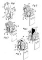
- the U-shaped part 2 comprises a U-shaped part 2, the legs 3 of which merge into an end part 5, which is widened over a large area and has receiving slots 4 for wire ends (not shown) in two at least approximately parallel planes.
- the side of the leg 3 protrude from the end parts 5, resilient, opposing contact tongues 6, each of which carries a contact surface 7 at the free end, which lie against one another under the effect of the spring tension of the contact tongues 6 with a predetermined pressure.
- the connecting member 1 forms a through contact, which contact can be checked at its separable contact tongues by inserting a test plug, as will be described in more detail below.
- connection device in question then comprises a connection strip 10, which has a number of connecting elements 1 arranged in a row next to one another, and comb strips 14 arranged thereon with grooves 15 for receiving cable cores (not shown).
- each connecting member 1 then comprises a U-shaped part 2, the legs 3 of which each merge into an area-widened end part 5 which has receiving slots 4 for wire ends, which lie opposite one another in two at least approximately parallel planes, with the leg 3 from the end parts laterally 5 resilient, opposite contact tongues 6 protrude, each carrying a contact surface 7 at the free end, which are under the action of the spring tension of the contact tongues 6 with a predetermined pressure.
- each connecting element 1 is used as an isolating contact. Accordingly, some or each of the links 1 are on one predetermined point 8 on one of the legs 3 separated and the separated leg parts are held apart by a comb web 12 extending over part or over the entire length of the terminal strip 10, with the contact tongues 6 and. Contact surfaces 7 a separating strip 13 extending over part or over the entire length of the terminal block 10 can be inserted from the front (FIG. 5).
Applications Claiming Priority (2)
| Application Number | Priority Date | Filing Date | Title |
|---|---|---|---|
| CH4330/88 | 1988-11-22 | ||
| CH4330/88A CH678467A5 (fr) | 1988-11-22 | 1988-11-22 |
Publications (4)
| Publication Number | Publication Date |
|---|---|
| EP0370380A2 true EP0370380A2 (fr) | 1990-05-30 |
| EP0370380A3 EP0370380A3 (fr) | 1991-08-07 |
| EP0370380B1 EP0370380B1 (fr) | 1995-11-15 |
| EP0370380B2 EP0370380B2 (fr) | 1998-11-18 |
Family
ID=4274073
Family Applications (1)
| Application Number | Title | Priority Date | Filing Date |
|---|---|---|---|
| EP89121172A Expired - Lifetime EP0370380B2 (fr) | 1988-11-22 | 1989-11-16 | Organe de connexion en matériau électriquement conducteur pour dispositifs de raccordement destinés à connecter des fils conducteurs électriquement isolés |
Country Status (3)
| Country | Link |
|---|---|
| EP (1) | EP0370380B2 (fr) |
| CH (1) | CH678467A5 (fr) |
| DE (1) | DE58909499D1 (fr) |
Cited By (5)
| Publication number | Priority date | Publication date | Assignee | Title |
|---|---|---|---|---|
| EP0765011A2 (fr) * | 1995-09-19 | 1997-03-26 | Reichle + De-Massari AG Elektro-Ingenieure | Méthode de fabrication d'un organe de connexion pour dispositif de raccordement destiné à connecter des tils conducteurs électriques |
| US5762516A (en) * | 1995-06-09 | 1998-06-09 | Minnesota Mining And Manufacturing Company | Contact and terminal connector having the contact |
| EP0654851B1 (fr) * | 1993-11-18 | 1999-01-20 | Alcatel | Réglette de raccordement équipée de contacts asymétriques |
| US5967826A (en) * | 1996-12-20 | 1999-10-19 | Pouyet S.A. | Terminal block with beveled edge for reduced crosstalk and method |
| WO2000004607A1 (fr) * | 1998-07-16 | 2000-01-27 | Reichle & De-Massari Ag | Ensemble de lames de contact destine a une barrette de connexion multiple pour des raccords de cables, et barrette de connexion multiple |
Families Citing this family (1)
| Publication number | Priority date | Publication date | Assignee | Title |
|---|---|---|---|---|
| DE19810562B4 (de) * | 1998-03-11 | 2006-10-05 | Homeway Gmbh | Trennvorrichtung |
Citations (2)
| Publication number | Priority date | Publication date | Assignee | Title |
|---|---|---|---|---|
| EP0041596A2 (fr) * | 1980-06-11 | 1981-12-16 | KRONE GmbH | Blocs de connexion pour connecter des fils isolés aux éléments de connexion à double contact |
| US4447105A (en) * | 1982-05-10 | 1984-05-08 | Illinois Tool Works Inc. | Terminal bridging adapter |
-
1988
- 1988-11-22 CH CH4330/88A patent/CH678467A5/de not_active IP Right Cessation
-
1989
- 1989-11-16 EP EP89121172A patent/EP0370380B2/fr not_active Expired - Lifetime
- 1989-11-16 DE DE58909499T patent/DE58909499D1/de not_active Expired - Fee Related
Patent Citations (2)
| Publication number | Priority date | Publication date | Assignee | Title |
|---|---|---|---|---|
| EP0041596A2 (fr) * | 1980-06-11 | 1981-12-16 | KRONE GmbH | Blocs de connexion pour connecter des fils isolés aux éléments de connexion à double contact |
| US4447105A (en) * | 1982-05-10 | 1984-05-08 | Illinois Tool Works Inc. | Terminal bridging adapter |
Cited By (8)
| Publication number | Priority date | Publication date | Assignee | Title |
|---|---|---|---|---|
| EP0654851B1 (fr) * | 1993-11-18 | 1999-01-20 | Alcatel | Réglette de raccordement équipée de contacts asymétriques |
| US5762516A (en) * | 1995-06-09 | 1998-06-09 | Minnesota Mining And Manufacturing Company | Contact and terminal connector having the contact |
| EP0765011A2 (fr) * | 1995-09-19 | 1997-03-26 | Reichle + De-Massari AG Elektro-Ingenieure | Méthode de fabrication d'un organe de connexion pour dispositif de raccordement destiné à connecter des tils conducteurs électriques |
| EP0765011A3 (fr) * | 1995-09-19 | 1998-06-17 | Reichle + De-Massari AG Elektro-Ingenieure | Méthode de fabrication d'un organe de connexion pour dispositif de raccordement destiné à connecter des tils conducteurs électriques |
| US5967826A (en) * | 1996-12-20 | 1999-10-19 | Pouyet S.A. | Terminal block with beveled edge for reduced crosstalk and method |
| WO2000004607A1 (fr) * | 1998-07-16 | 2000-01-27 | Reichle & De-Massari Ag | Ensemble de lames de contact destine a une barrette de connexion multiple pour des raccords de cables, et barrette de connexion multiple |
| US6514094B1 (en) | 1998-07-16 | 2003-02-04 | Reichle & De-Massari Ag | Set of contact blades in a multiple connector strip for cable connectors, and multiple connector strip |
| KR100712166B1 (ko) * | 1998-07-16 | 2007-04-27 | 라이힐레 운트 데-마싸리 아게 | 케이블 연결용 모듈식 다중 연결 스트랩 |
Also Published As
| Publication number | Publication date |
|---|---|
| DE58909499D1 (de) | 1995-12-21 |
| EP0370380B2 (fr) | 1998-11-18 |
| EP0370380B1 (fr) | 1995-11-15 |
| CH678467A5 (fr) | 1991-09-13 |
| EP0370380A3 (fr) | 1991-08-07 |
Similar Documents
| Publication | Publication Date | Title |
|---|---|---|
| DE4015238C2 (fr) | ||
| DE2721748C2 (de) | Elektrische Anschlußklemme | |
| EP0075150A2 (fr) | Moyen pour établir un contact simple ou multiple pour un élément de raccordement sans soudage, sans vis et sans dénudage | |
| DE2804478A1 (de) | Vorrichtung und verfahren zur herstellung eines loet-, schraub- und abisolierfreien kontaktes an einem feststehenden anschlusselement, insbesondere fuer die fernmeldelinientechnik | |
| DE2736664C2 (de) | Elektrische Anschluß- und/oder Verbindungsklemme, insbesondere Reihenklemme | |
| DE3014796A1 (de) | Ueberspannungsableitervorrichtung fuer anschlussleisten der fernmeldetechnik | |
| DE3435789A1 (de) | Halterungsblock zum verbinden von verbindungselementen mit der platte eines gedruckten schaltkreises | |
| DE4102784C2 (de) | Anschlußklemme | |
| DE2724235A1 (de) | Elektrisches verbindersystem | |
| EP0370380B1 (fr) | Organe de connexion en matériau électriquement conducteur pour dispositifs de raccordement destinés à connecter des fils conducteurs électriquement isolés | |
| DE19708649A1 (de) | Elektrische Klemme mit Querbrücker | |
| DE8132718U1 (de) | Anschlußvorrichtung, insbesondere für Fernmeldeleitungen | |
| DE4042306C2 (de) | Endverzweiger mit Prüfstecker | |
| DE19714634A1 (de) | Element zum Anschließen eines Schirmkabels | |
| DE3621223A1 (de) | Anschlussleiste fuer elektrische leitungen | |
| DE2424419C3 (de) | Kontaktanordnung zur Herstellung einer lösbaren elektrischen Verbindung zwischen einem Leiterband und mindestens einer Steckkarte | |
| DE8604746U1 (de) | Schneidklemme | |
| DE29917825U1 (de) | Verbindungselement mit Querverbindung | |
| DE1762567C3 (de) | Rangierleiste | |
| DE4343444C2 (de) | Schneid-Klemm-Kontaktelement | |
| DE8222551U1 (de) | Steckbarer Klemmensockel für mehrpolige Messerleisten | |
| DE19810562B4 (de) | Trennvorrichtung | |
| DE3229165C2 (de) | Federleiste mit mindestens einer Reihe von Lötfahnen | |
| DD295958A5 (de) | Verteilereinrichtung fuer telekommunikationsanlagen | |
| DE1762566B1 (de) | Trennleiste fuer Fernmeldeanlagen |
Legal Events
| Date | Code | Title | Description |
|---|---|---|---|
| PUAI | Public reference made under article 153(3) epc to a published international application that has entered the european phase |
Free format text: ORIGINAL CODE: 0009012 |
|
| AK | Designated contracting states |
Kind code of ref document: A2 Designated state(s): DE FR GB IT |
|
| PUAL | Search report despatched |
Free format text: ORIGINAL CODE: 0009013 |
|
| AK | Designated contracting states |
Kind code of ref document: A3 Designated state(s): DE FR GB IT |
|
| RHK1 | Main classification (correction) |
Ipc: H01R 4/24 |
|
| 17P | Request for examination filed |
Effective date: 19920201 |
|
| 17Q | First examination report despatched |
Effective date: 19940126 |
|
| GRAA | (expected) grant |
Free format text: ORIGINAL CODE: 0009210 |
|
| AK | Designated contracting states |
Kind code of ref document: B1 Designated state(s): DE FR GB IT |
|
| REF | Corresponds to: |
Ref document number: 58909499 Country of ref document: DE Date of ref document: 19951221 |
|
| GBT | Gb: translation of ep patent filed (gb section 77(6)(a)/1977) |
Effective date: 19951218 |
|
| ET | Fr: translation filed | ||
| ITF | It: translation for a ep patent filed |
Owner name: STUDIO JAUMANN |
|
| PLBQ | Unpublished change to opponent data |
Free format text: ORIGINAL CODE: EPIDOS OPPO |
|
| PLBI | Opposition filed |
Free format text: ORIGINAL CODE: 0009260 |
|
| PLBF | Reply of patent proprietor to notice(s) of opposition |
Free format text: ORIGINAL CODE: EPIDOS OBSO |
|
| 26 | Opposition filed |
Opponent name: QUANTE AG Effective date: 19960813 |
|
| PLBF | Reply of patent proprietor to notice(s) of opposition |
Free format text: ORIGINAL CODE: EPIDOS OBSO |
|
| PLAW | Interlocutory decision in opposition |
Free format text: ORIGINAL CODE: EPIDOS IDOP |
|
| PLAW | Interlocutory decision in opposition |
Free format text: ORIGINAL CODE: EPIDOS IDOP |
|
| PUAH | Patent maintained in amended form |
Free format text: ORIGINAL CODE: 0009272 |
|
| STAA | Information on the status of an ep patent application or granted ep patent |
Free format text: STATUS: PATENT MAINTAINED AS AMENDED |
|
| 27A | Patent maintained in amended form |
Effective date: 19981118 |
|
| AK | Designated contracting states |
Kind code of ref document: B2 Designated state(s): DE FR GB IT |
|
| GBTA | Gb: translation of amended ep patent filed (gb section 77(6)(b)/1977) | ||
| ITF | It: translation for a ep patent filed |
Owner name: STUDIO JAUMANN P. & C. S.N.C. |
|
| ET3 | Fr: translation filed ** decision concerning opposition | ||
| REG | Reference to a national code |
Ref country code: GB Ref legal event code: IF02 |
|
| PGFP | Annual fee paid to national office [announced via postgrant information from national office to epo] |
Ref country code: GB Payment date: 20041111 Year of fee payment: 16 |
|
| PGFP | Annual fee paid to national office [announced via postgrant information from national office to epo] |
Ref country code: FR Payment date: 20041118 Year of fee payment: 16 |
|
| PGFP | Annual fee paid to national office [announced via postgrant information from national office to epo] |
Ref country code: DE Payment date: 20041215 Year of fee payment: 16 |
|
| PG25 | Lapsed in a contracting state [announced via postgrant information from national office to epo] |
Ref country code: IT Free format text: LAPSE BECAUSE OF NON-PAYMENT OF DUE FEES;WARNING: LAPSES OF ITALIAN PATENTS WITH EFFECTIVE DATE BEFORE 2007 MAY HAVE OCCURRED AT ANY TIME BEFORE 2007. THE CORRECT EFFECTIVE DATE MAY BE DIFFERENT FROM THE ONE RECORDED. Effective date: 20051116 Ref country code: GB Free format text: LAPSE BECAUSE OF NON-PAYMENT OF DUE FEES Effective date: 20051116 |
|
| PG25 | Lapsed in a contracting state [announced via postgrant information from national office to epo] |
Ref country code: DE Free format text: LAPSE BECAUSE OF NON-PAYMENT OF DUE FEES Effective date: 20060601 |
|
| GBPC | Gb: european patent ceased through non-payment of renewal fee |
Effective date: 20051116 |
|
| PG25 | Lapsed in a contracting state [announced via postgrant information from national office to epo] |
Ref country code: FR Free format text: LAPSE BECAUSE OF NON-PAYMENT OF DUE FEES Effective date: 20060731 |
|
| REG | Reference to a national code |
Ref country code: FR Ref legal event code: ST Effective date: 20060731 |