EP0370280B1 - Vorrichtung zum Abbrechen von Schornsteinen - Google Patents
Vorrichtung zum Abbrechen von Schornsteinen Download PDFInfo
- Publication number
- EP0370280B1 EP0370280B1 EP89120240A EP89120240A EP0370280B1 EP 0370280 B1 EP0370280 B1 EP 0370280B1 EP 89120240 A EP89120240 A EP 89120240A EP 89120240 A EP89120240 A EP 89120240A EP 0370280 B1 EP0370280 B1 EP 0370280B1
- Authority
- EP
- European Patent Office
- Prior art keywords
- equipment according
- suspension
- chimney
- demolition
- lowering
- Prior art date
- Legal status (The legal status is an assumption and is not a legal conclusion. Google has not performed a legal analysis and makes no representation as to the accuracy of the status listed.)
- Expired - Lifetime
Links
- 239000000725 suspension Substances 0.000 claims abstract description 56
- 210000003128 head Anatomy 0.000 claims description 9
- 239000004567 concrete Substances 0.000 claims description 4
- 239000011150 reinforced concrete Substances 0.000 claims description 4
- 229910000831 Steel Inorganic materials 0.000 claims 1
- 238000010276 construction Methods 0.000 claims 1
- 230000037431 insertion Effects 0.000 claims 1
- 238000003780 insertion Methods 0.000 claims 1
- 239000010959 steel Substances 0.000 claims 1
- 230000006978 adaptation Effects 0.000 description 3
- 230000000284 resting effect Effects 0.000 description 2
- 238000004519 manufacturing process Methods 0.000 description 1
- 238000000034 method Methods 0.000 description 1
- 230000002787 reinforcement Effects 0.000 description 1
Images


Classifications
-
- E—FIXED CONSTRUCTIONS
- E04—BUILDING
- E04G—SCAFFOLDING; FORMS; SHUTTERING; BUILDING IMPLEMENTS OR AIDS, OR THEIR USE; HANDLING BUILDING MATERIALS ON THE SITE; REPAIRING, BREAKING-UP OR OTHER WORK ON EXISTING BUILDINGS
- E04G23/00—Working measures on existing buildings
- E04G23/08—Wrecking of buildings
- E04G2023/087—Wrecking of buildings of chimneys, smoke stacks or the like
Definitions
- the invention relates to a device for breaking off chimneys made of masonry, concrete or reinforced concrete, in particular of high chimneys, by means of a demolition tool which gradually removes the chimney shaft from the chimney head to the chimney foot, e.g. is already known from patent application EP-A-0133630.
- the invention has for its object to provide a device which allows chimneys and in particular tall chimneys to be broken off by machine with optimum safety and in a rational or economical manner.
- the generic device is characterized by a work platform that can be attached to the mouth end of the chimney shaft and suspension devices distributed over the circumference of the stage, each with at least one vertically guided lowering piston that can be locked in different height positions, in that the work platform is suspended in the interior of the chimney shaft and that a suspension arm is pivotally mounted on the upper piston end of the lowering piston, which engages over the chimney wall in the pivoted-out position.
- the invention further teaches that the work platform has supporting devices distributed over the circumference of the stage with support arms which can be adjusted against the inside of the chimney.
- the invention is based on the knowledge that an excavator with a demolition tool can then be used with sufficient freedom of movement and optimal safety for demolition of chimneys if a work platform is installed for this excavator, which is gradually lowered from the chimney head to the chimney base in accordance with the progress of demolition can be.
- a work platform can be lifted to the level of the chimney mouth in the same way as the excavator by means of an approved conveyor scaffold and hung there in the chimney shaft.
- the work platform is suspended from the chimney wall using the all-round suspension devices. Then the lowering pistons are extended, so to speak, ie the work platform hangs at the lower end the lowering piston and the suspension arms overlap the chimney wall.
- the suspension arms are swiveled in or back in individually and one after the other, so that the chimney wall can be demolished shortly above the level of the work platform.
- the lowering piston in question is then moved down or retracted by the extent of the demolition progress and the relevant suspension arm is pivoted out again, so it then overlaps the chimney wall at the demolition point that has migrated downward.
- the work platform which regularly has a polygon-like circumference, is moved on each suspension arm or lowering piston, so that finally all working pistons with their suspension arms are retracted by the degree of progress of the dismantling or moved down.
- the extent of the demolition progress corresponds to the maximum piston stroke.
- the invention provides that the support devices are connected in a radial extension to the suspension devices and the suspension devices with the support devices with the interposition of cantilever arms in the radial direction can be moved forward or can be seized.
- the cantilever arms can be designed as profile supports, rack and pinion drives or cylinder piston arrangements with screwable connecting flanges.
- profile beams can be successively connected to one another via their connecting flanges and inserted between the suspension devices and the working platform.
- the suspension devices each have a guide tube flanged directly to the working platform or to an intermediate cantilever arm in a vertical orientation for the lowering piston which is height-adjustable and lockable in the guide tube, and that the guide tube and the lowering piston are in predetermined height distances aligned cross holes to the have locking bolts. In this way, the extent of the demolition progress can vary over the height of the piston stroke, so that the working platform only has to be lowered after several demolition steps that have taken place over the chimney circumference.
- the guide tube is designed as a rectangular tube and the lowering piston as an I-profile and longitudinal guides, for example ball guides or roller guides, are arranged as ladder-shaped flat cages or roller carriages for the lowering piston.
- the lowering piston expediently has a footplate at its lower end as a stop for the guide tube and consequently the work platform, as well as suspension eyes at its upper end.
- the work platform can be attached to a conveyor frame in the chimney mouth.
- the vertically guided lowering piston carries two horizontal bearing cheeks at its upper end and the suspension arm is pivotally mounted on a horizontal bearing pin between these bearing cheeks and can be locked in a horizontal position by means of locking pins which can be inserted into aligned cross holes on one or both sides of the bearing pin.
- the bearing cheeks and the suspension arm can consist of U-profiles. Each suspension arm can at its resting end have a height-adjustable support plate in order to achieve perfect support on the demolition surface of the chimney shaft.
- the inner ends of the suspension arms and the guide tubes are connected to one another in the region of their inner connecting flanges via chain or cable pulls and thereby the working platform by means of Chain or cable pulling devices can be lowered on the suspended lowering pistons. Lowering the platform in this way is necessary before each demolition cycle. The lowered working platform then rests on the base plates of the lowering pistons and is supported against the inner wall of the shaft.
- each guide tube is surrounded by a double collar with a connecting flange for the working platform or the intermediate cantilever arm and one or two support arms are pivotably mounted in a horizontal plane between the two collars and can be fixed in a position against the inner chimney wall, e.g. by means of a chain hoist or linkage connecting both support arms, so that the support arms cannot swing out independently and the support is thereby lost.
- the support arms can have support plates which can be pivoted or articulated at the end.
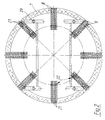
- the figures show a device for breaking off chimneys made of masonry, concrete or reinforced concrete, in particular free-standing chimneys of great height.
- the chimney is broken off by means of a successive removal of the chimney shaft 1 from the chimney head to the chimney foot Demolition tool 2, which is attached to the cantilever arm 3 of an excavator 4 according to the embodiment.
- a work platform 5 is suspended in the chimney shaft 1 at its mouth end, specifically with suspension devices 6 distributed over the circumference of the stage, each with at least one vertically guided lowering piston 7, which can be locked in different height positions, and a suspension arm 8 pivotably mounted at the upper piston end, which in the pivoted-out position Spread over chimney wall.
- the work platform 5 also has support devices 9 distributed over the circumference of the stage, with support arms 10 which can be adjusted against the inside of the chimney.
- the support devices 9 adjoin the suspension devices 6 in a radial extension.
- the suspension devices 6 can be advanced or pre-attached with the support devices 9 with the interposition of cantilever arms 11 in the radial direction in order to always allow adaptation to the chimney diameter which increases from the chimney head to the chimney foot.
- the working platform 5 has a polygon-like circumference, consists essentially of cross-beam-shaped profile beams 12 and a platform 13 carried by them.
- the cantilever arms 11 are designed as profile beams with screwable connecting flanges 14.
- the working platform 5 and the suspension devices 6 have such connecting flanges 14.
- Catwalks 15 can be fastened on the cantilever arms 11.
- Safety nets 16 can be suspended between the cantilever arms 11, which is only indicated.
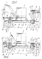
- the suspension devices 6 each have a directly on the work platform 5 or on an intermediate cantilever 11 in a vertical orientation flanged guide tube 17 for the lowering piston 7 which is height-adjustable in the guide tube and lockable at different heights.
- the guide tube 17 and the lowering piston 7 have aligned cross bores 18 for inserting locking bolts at predetermined height intervals.
- the guide tube 17 is designed as a rectangular tube and the lowering piston 7 as an I-profile. Roller guides 19 for the lowering piston 7 are arranged in the guide tube 17.
- the lowering piston 7 has a base plate 20 at its lower end and suspension eyes at its upper end. In the lowered position, the working platform 5 rests on the base plates 20 of the lowering piston 7.
- Each of the distributed lowering pistons 7 carries two horizontal bearing cheeks 21 at its upper end. Between the bearing cheeks 21, the suspension arm 8 is pivotably mounted on a horizontal bearing pin 22 and can be locked in a horizontal position by means of locking pins which can be inserted into aligned cross bores 23 on one or both sides of the bearing pin 22, when the suspension arm 8 overlaps the chimney wall and the working platform 5 is suspended with the lowering piston 7 interposed.
- the bearing cheeks 21 and the suspension arm 8 consist of U-profiles.
- Each suspension arm 8 has a height-adjustable support plate 24 at its resting end for adaptation to the respective demolition surface.
- each Guide tube 17 is surrounded by a double collar 26 with a connecting flange 14.
- one or two support arms 10 are pivotally mounted in the horizontal plane and can be fixed in the position against the chimney inner wall, for example by means of a chain hoist 27 or linkage connecting the two support arms.
- the support arms 10 are pivoted apart.
- the support arms 10 have pivotable or articulated support plates 28 in order to achieve perfect support against the chimney inner wall.
- a chimney is demolished as follows:
- the excavator 4 begins its demolition work in the region of a suspension arm 8 which is pivoted back or in. After the demolition has taken place Over a predetermined height, which must not exceed the maximum piston stroke of the lowering piston 7, the suspension arm 8 in question is pivoted back into its starting position spanning the chimney wall. The lowering piston 7 in question is then automatically in the retracted position.
- the lowering pistons 7 touch the ground. Ultimately, this also applies to the work platform.
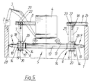
- cantilever arms 11 are increasingly used between the working platform 5 and the guide tubes 17 for the lowering pistons 7 with the support arms 10, so that the support arms 10 can always be positioned properly against the increasing chimney inner wall and for centering and movement-free support of the work platform 5.
- substructures 31 which can be covered with carriages 30 can be connected to the cantilever arms 11 in order to achieve an expansion of the work platform 5 into the region of the chimney wall, so that the excavator 4 moves forward from the center of the chimney and can carry out demolition work from the outside with demolition tool 2 spanning the chimney wall.
- use is on the catwalks 15 and safety nets 16 are dispensed with. This is only indicated in some areas in FIG. 6.
Landscapes
- Engineering & Computer Science (AREA)
- Architecture (AREA)
- Chemical & Material Sciences (AREA)
- Chemical Kinetics & Catalysis (AREA)
- Electrochemistry (AREA)
- Mechanical Engineering (AREA)
- Civil Engineering (AREA)
- Structural Engineering (AREA)
- Working Measures On Existing Buildindgs (AREA)
Priority Applications (1)
| Application Number | Priority Date | Filing Date | Title |
|---|---|---|---|
| AT89120240T ATE71690T1 (de) | 1988-11-24 | 1989-11-01 | Vorrichtung zum abbrechen von schornsteinen. |
Applications Claiming Priority (2)
| Application Number | Priority Date | Filing Date | Title |
|---|---|---|---|
| DE3839677 | 1988-11-24 | ||
| DE3839677A DE3839677A1 (de) | 1988-11-24 | 1988-11-24 | Vorrichtung zum abbrechen von schornsteinen |
Publications (2)
| Publication Number | Publication Date |
|---|---|
| EP0370280A1 EP0370280A1 (de) | 1990-05-30 |
| EP0370280B1 true EP0370280B1 (de) | 1992-01-15 |
Family
ID=6367809
Family Applications (1)
| Application Number | Title | Priority Date | Filing Date |
|---|---|---|---|
| EP89120240A Expired - Lifetime EP0370280B1 (de) | 1988-11-24 | 1989-11-01 | Vorrichtung zum Abbrechen von Schornsteinen |
Country Status (5)
| Country | Link |
|---|---|
| US (1) | US4955457A (enExample) |
| EP (1) | EP0370280B1 (enExample) |
| JP (1) | JPH06105013B2 (enExample) |
| AT (1) | ATE71690T1 (enExample) |
| DE (1) | DE3839677A1 (enExample) |
Families Citing this family (23)
| Publication number | Priority date | Publication date | Assignee | Title |
|---|---|---|---|---|
| FR2678311B1 (fr) * | 1991-06-25 | 1993-10-29 | Morel Sa | Outil, procede et materiel de demolition de murs, en particulier de cheminees. |
| DE19722185A1 (de) * | 1997-05-27 | 1998-12-10 | Michael Barnsteiner | Abbruchgerät für Baukörper und Verfahren zum Abbruch von Baukörpern |
| DE29812795U1 (de) | 1998-07-17 | 1998-12-03 | Ostermeyer Anbautechnik GmbH, 88448 Attenweiler | Vorrichtung zum Abbrechen eines eine umlaufende Wandung aufweisenden Bauwerks wie einem Schornstein oder einem Kühlturm |
| DE19928574C2 (de) * | 1999-06-23 | 2001-11-15 | Stingl Montage Und Befestigung | Arbeitsbühne |
| JP3592313B2 (ja) * | 2002-05-10 | 2004-11-24 | 大王製紙株式会社 | 塔槽体の内壁面作業装置 |
| US7607481B2 (en) * | 2007-05-16 | 2009-10-27 | Gulfstream Services, Inc. | Method and apparatus for dropping a pump down plug or ball |
| DE202008004374U1 (de) | 2008-03-28 | 2008-08-14 | Barnsteiner, Michael | Vorrichtung zum Abbrechen von Bauwerken |
| DE102010006427A1 (de) | 2010-02-01 | 2011-12-15 | Tvf Altwert Gmbh | Einrichtung zum Abbau von Innenschornsteinen in Industrieschornsteinen und ähnlichen Bauwerken |
| EP2918748B1 (en) * | 2012-11-08 | 2017-12-27 | Besterra Co., Ltd. | Dismantling method for smokestacks |
| US9279262B2 (en) * | 2013-12-09 | 2016-03-08 | International Chimney Corporation | Chimney demolition vehicle |
| DE102016113227B3 (de) * | 2016-07-18 | 2017-12-21 | Karl Hartinger Kranbetrieb Gmbh & Co.Kg | Arbeitsvorrichtung, insbesondere zur Verwendung bei der Demontage eines Betonturmes |
| DE102016113224B3 (de) * | 2016-07-18 | 2017-11-16 | Karl Hartinger Kranbetrieb Gmbh & Co.Kg | Verfahren zur Demontage von Betontürmen |
| US10890003B2 (en) * | 2016-12-16 | 2021-01-12 | International Chimney Corporation | Liner removal apparatus |
| CN108868194B (zh) * | 2018-07-30 | 2023-12-22 | 威海新特重工股份有限公司 | 一种烟囱拆除装置及烟囱拆除方法 |
| CN112049462A (zh) * | 2020-08-07 | 2020-12-08 | 新兴铸管股份有限公司 | 一种高空建筑物的机械拆除工艺 |
| DE102021000427A1 (de) | 2020-08-25 | 2022-03-03 | Wörmann Team GmbH & Co. KG | Vorrichtung und Verfahren zum Demontieren eines Betonturms, insbesondere Betonsegmentturms, einer Windenergieanlage |
| DE102020127750A1 (de) | 2020-10-21 | 2022-04-21 | Karl Hartinger Kranbetrieb Gmbh & Co Kg | Vorrichtung und Verfahren zum Trennen von Spannelementen |
| CN112482740B (zh) * | 2020-10-27 | 2022-05-10 | 中国一冶集团有限公司 | 一种大型凹曲作业面施工作业装置及其施工作业方法 |
| CN112746736A (zh) * | 2021-01-13 | 2021-05-04 | 刘红军 | 一种烟囱拆除施工可移动工作平台 |
| RU2753332C1 (ru) * | 2021-02-19 | 2021-08-13 | Александр Васильевич Сало | Машина для демонтажа дымовых труб |
| US12044020B2 (en) | 2021-08-05 | 2024-07-23 | Veit & Company | Demolition system |
| CN117052192A (zh) * | 2023-04-12 | 2023-11-14 | 同济大学 | 一种高层建筑拆除方法与拆楼机平台 |
| CN119195567B (zh) * | 2024-11-05 | 2026-01-23 | 中国二十二冶集团有限公司 | 一种混凝土烟囱高空拆除方法 |
Family Cites Families (15)
| Publication number | Priority date | Publication date | Assignee | Title |
|---|---|---|---|---|
| US1218008A (en) * | 1916-08-28 | 1917-03-06 | Hiram A Smith | Device for use in erecting silos. |
| US1652403A (en) * | 1926-12-13 | 1927-12-13 | Nat Conveyor Company | Building derrick for bunkers |
| US2221133A (en) * | 1940-02-09 | 1940-11-12 | Glenn V Gladville | Scaffold |
| US2710418A (en) * | 1952-06-04 | 1955-06-14 | Ayers B Putnam | Power scaffolds |
| DE1280534B (de) * | 1962-12-01 | 1968-10-17 | Babcock & Wilcox Dampkessel We | Schutzhaube fuer ein Arbeitsgeruest fuer den Industrie-Schornsteinbau |
| US3346300A (en) * | 1966-08-08 | 1967-10-10 | Louis A Grant | Blast furnace lining removing machine |
| US3370888A (en) * | 1965-11-08 | 1968-02-27 | Skendrovic Lawrence | Furnace refractory delining apparatus |
| US4068895A (en) * | 1976-07-01 | 1978-01-17 | O. W. Reese, Inc. | Demolition machine for delining a furnace |
| US4407392A (en) * | 1981-08-31 | 1983-10-04 | Western Electric Company, Inc. | Safety scaffold for metal melting furnaces |
| GB2120308B (en) * | 1982-05-07 | 1985-12-24 | Black And Son W B | Improvements in the piecemeal demolition of chimneys |
| US4607994A (en) * | 1982-05-17 | 1986-08-26 | Tellus Maskin Ab | Transport arrangement especially for lining material |
| EP0133630A1 (en) * | 1983-08-05 | 1985-03-06 | W.B. Black & Sons (Holdings) Limited | Improvements in the piecemeal demolition of chimneys |
| DE3512212C2 (de) * | 1985-04-03 | 1997-04-24 | Michael Barnsteiner | Verfahren und Vorrichtung zum Abbruch von Schornsteinen |
| DE3635597C2 (de) * | 1986-10-20 | 1996-08-29 | Michael Barnsteiner | Vorrichtung zum Abbruch von Schornsteinen od. dgl. sowie Verfahren zur Montage der Vorrichtung |
| US4861112A (en) * | 1988-07-26 | 1989-08-29 | Louis A. Grant, Inc. | Apparatus for cleaning aluminum cells |
-
1988
- 1988-11-24 DE DE3839677A patent/DE3839677A1/de active Granted
-
1989
- 1989-11-01 AT AT89120240T patent/ATE71690T1/de active
- 1989-11-01 EP EP89120240A patent/EP0370280B1/de not_active Expired - Lifetime
- 1989-11-22 JP JP1302293A patent/JPH06105013B2/ja not_active Expired - Lifetime
- 1989-11-22 US US07/440,900 patent/US4955457A/en not_active Expired - Fee Related
Also Published As
| Publication number | Publication date |
|---|---|
| ATE71690T1 (de) | 1992-02-15 |
| EP0370280A1 (de) | 1990-05-30 |
| DE3839677A1 (de) | 1990-05-31 |
| US4955457A (en) | 1990-09-11 |
| DE3839677C2 (enExample) | 1992-03-05 |
| JPH06105013B2 (ja) | 1994-12-21 |
| JPH02243878A (ja) | 1990-09-27 |
Similar Documents
| Publication | Publication Date | Title |
|---|---|---|
| EP0370280B1 (de) | Vorrichtung zum Abbrechen von Schornsteinen | |
| DE4431503B4 (de) | Maschine zur Vorbereitung von Schweißarbeiten auf einem Gleis | |
| DE2947210A1 (de) | Geraet zum heben gleitender formen an stahlstangen zur herstellung von betonbauwerken u.dgl. | |
| EP2288770B1 (de) | Vorrichtung zum abbrechen von bauwerken | |
| DE3049687C2 (enExample) | ||
| DE3635597C2 (de) | Vorrichtung zum Abbruch von Schornsteinen od. dgl. sowie Verfahren zur Montage der Vorrichtung | |
| DE3512212C2 (de) | Verfahren und Vorrichtung zum Abbruch von Schornsteinen | |
| DE2630136A1 (de) | Verfahren zur weitergabe von bohrstangenelementen, bohrturm und bohrturmeinheit zur durchfuehrung des verfahrens | |
| DE2748340A1 (de) | Kletterkran | |
| WO2004083561A1 (de) | Vorrichtung und verfahren zum abbruch von bauwerken | |
| EP0105504B1 (de) | Verfahren und Vorrichtung zum Demontieren von Deckenschalungen | |
| DE10225183A1 (de) | Abbruchgerät | |
| DE2015940B2 (de) | Vorrichtung zum verstellen von gleitschalungen | |
| DE69400159T2 (de) | Gerüstboden und Montageverfahren für Gerüste mit diesem Boden | |
| EP1272732B1 (de) | Gerät zum transport und zur handhabung von rohren und bohrgestängen | |
| DE2461251C3 (de) | Vorrichtung für die Vormontage, den Transport und den Einbau eines Strecken- bzw. Tunnelausbaus | |
| DE2510628B2 (de) | Reparaturverfahren fuer hochoefen | |
| EP0724669B1 (de) | Verfahren zum umsetzen eines verfahrbaren arbeitsgerüstes um brückenpfeiler und vorrichtung zum durchführen des verfahrens | |
| DE102009030741B4 (de) | Vorrichtung und Verfahren zur Montage und/oder Demontage eines Kranauslegers und Kran mit einer derartigen Vorrichtung | |
| DE9206391U1 (de) | Arbeitsgerät zum Abbruch oder Aufbau von Mauern | |
| WO2019034209A1 (de) | Vorrichtung und verfahren zum rückbauen und zerkleinern vertikal ausgerichteter objekte | |
| DE3839261C1 (en) | Process and apparatus for pulling down essentially hollow-cylindrical structures, such as chimneys | |
| DE3545965C2 (enExample) | ||
| DE2432851A1 (de) | Verfahren zum umsetzen eines schalkoerpers und fuer das verfahren eingerichtete schalung | |
| CH668800A5 (en) | Tall chimney demolition mechanism - has annular working platform, travelling on vertical rails on chimney outer wall and fitted with support columns |
Legal Events
| Date | Code | Title | Description |
|---|---|---|---|
| PUAI | Public reference made under article 153(3) epc to a published international application that has entered the european phase |
Free format text: ORIGINAL CODE: 0009012 |
|
| AK | Designated contracting states |
Kind code of ref document: A1 Designated state(s): AT BE FR GB IT NL |
|
| 17P | Request for examination filed |
Effective date: 19900718 |
|
| 17Q | First examination report despatched |
Effective date: 19910507 |
|
| GRAA | (expected) grant |
Free format text: ORIGINAL CODE: 0009210 |
|
| AK | Designated contracting states |
Kind code of ref document: B1 Designated state(s): AT BE FR GB IT NL |
|
| REF | Corresponds to: |
Ref document number: 71690 Country of ref document: AT Date of ref document: 19920215 Kind code of ref document: T |
|
| ITF | It: translation for a ep patent filed | ||
| GBT | Gb: translation of ep patent filed (gb section 77(6)(a)/1977) | ||
| ET | Fr: translation filed | ||
| PLBE | No opposition filed within time limit |
Free format text: ORIGINAL CODE: 0009261 |
|
| STAA | Information on the status of an ep patent application or granted ep patent |
Free format text: STATUS: NO OPPOSITION FILED WITHIN TIME LIMIT |
|
| 26N | No opposition filed | ||
| PGFP | Annual fee paid to national office [announced via postgrant information from national office to epo] |
Ref country code: GB Payment date: 19941110 Year of fee payment: 6 |
|
| PGFP | Annual fee paid to national office [announced via postgrant information from national office to epo] |
Ref country code: FR Payment date: 19941125 Year of fee payment: 6 |
|
| PGFP | Annual fee paid to national office [announced via postgrant information from national office to epo] |
Ref country code: AT Payment date: 19941130 Year of fee payment: 6 |
|
| PGFP | Annual fee paid to national office [announced via postgrant information from national office to epo] |
Ref country code: BE Payment date: 19941205 Year of fee payment: 6 |
|
| PG25 | Lapsed in a contracting state [announced via postgrant information from national office to epo] |
Ref country code: GB Effective date: 19951101 Ref country code: AT Effective date: 19951101 |
|
| PG25 | Lapsed in a contracting state [announced via postgrant information from national office to epo] |
Ref country code: BE Effective date: 19951130 |
|
| BERE | Be: lapsed |
Owner name: ROBOTA G.M.B.H. FEUERUNGS- UND SCHORNSTEINBAU Effective date: 19951130 |
|
| GBPC | Gb: european patent ceased through non-payment of renewal fee |
Effective date: 19951101 |
|
| PG25 | Lapsed in a contracting state [announced via postgrant information from national office to epo] |
Ref country code: FR Effective date: 19960731 |
|
| REG | Reference to a national code |
Ref country code: FR Ref legal event code: ST |
|
| NLS | Nl: assignments of ep-patents |
Owner name: WESTSCHROTT INDUSTRIE-ABBRUCH GMBH & CO. ROBOTA KG |
|
| PGFP | Annual fee paid to national office [announced via postgrant information from national office to epo] |
Ref country code: NL Payment date: 20011130 Year of fee payment: 13 |
|
| PG25 | Lapsed in a contracting state [announced via postgrant information from national office to epo] |
Ref country code: NL Free format text: LAPSE BECAUSE OF NON-PAYMENT OF DUE FEES Effective date: 20030601 |
|
| NLV4 | Nl: lapsed or anulled due to non-payment of the annual fee |
Effective date: 20030601 |
|
| PG25 | Lapsed in a contracting state [announced via postgrant information from national office to epo] |
Ref country code: IT Free format text: LAPSE BECAUSE OF NON-PAYMENT OF DUE FEES Effective date: 20051101 |