EP0370184A1 - Vorrichtung zur Verbrennung von Haus- und Sondermüll - Google Patents
Vorrichtung zur Verbrennung von Haus- und Sondermüll Download PDFInfo
- Publication number
- EP0370184A1 EP0370184A1 EP89116364A EP89116364A EP0370184A1 EP 0370184 A1 EP0370184 A1 EP 0370184A1 EP 89116364 A EP89116364 A EP 89116364A EP 89116364 A EP89116364 A EP 89116364A EP 0370184 A1 EP0370184 A1 EP 0370184A1
- Authority
- EP
- European Patent Office
- Prior art keywords
- boiler
- burners
- gases
- combustion gases
- waste
- Prior art date
- Legal status (The legal status is an assumption and is not a legal conclusion. Google has not performed a legal analysis and makes no representation as to the accuracy of the status listed.)
- Granted
Links
- 238000002485 combustion reaction Methods 0.000 title description 5
- 239000002440 industrial waste Substances 0.000 title 1
- 239000000567 combustion gas Substances 0.000 claims abstract description 20
- 238000000034 method Methods 0.000 claims abstract description 13
- 239000002918 waste heat Substances 0.000 claims abstract description 6
- 239000002912 waste gas Substances 0.000 claims abstract 4
- 239000007789 gas Substances 0.000 claims description 23
- 239000002699 waste material Substances 0.000 claims description 6
- 238000007664 blowing Methods 0.000 claims 1
- 238000004140 cleaning Methods 0.000 claims 1
- UGFAIRIUMAVXCW-UHFFFAOYSA-N Carbon monoxide Chemical compound [O+]#[C-] UGFAIRIUMAVXCW-UHFFFAOYSA-N 0.000 abstract description 5
- 238000006243 chemical reaction Methods 0.000 abstract description 5
- 229910002091 carbon monoxide Inorganic materials 0.000 abstract description 4
- 229940105305 carbon monoxide Drugs 0.000 abstract 1
- 238000009434 installation Methods 0.000 abstract 1
- 239000003546 flue gas Substances 0.000 description 6
- QVGXLLKOCUKJST-UHFFFAOYSA-N atomic oxygen Chemical compound [O] QVGXLLKOCUKJST-UHFFFAOYSA-N 0.000 description 4
- 239000001301 oxygen Substances 0.000 description 4
- 229910052760 oxygen Inorganic materials 0.000 description 4
- 239000003245 coal Substances 0.000 description 3
- 238000010304 firing Methods 0.000 description 3
- ATUOYWHBWRKTHZ-UHFFFAOYSA-N Propane Chemical compound CCC ATUOYWHBWRKTHZ-UHFFFAOYSA-N 0.000 description 2
- 238000004056 waste incineration Methods 0.000 description 2
- 230000001154 acute effect Effects 0.000 description 1
- 229910052799 carbon Inorganic materials 0.000 description 1
- 238000011109 contamination Methods 0.000 description 1
- 238000006477 desulfuration reaction Methods 0.000 description 1
- 230000023556 desulfurization Effects 0.000 description 1
- 238000006073 displacement reaction Methods 0.000 description 1
- 239000010791 domestic waste Substances 0.000 description 1
- 238000005259 measurement Methods 0.000 description 1
- 239000001294 propane Substances 0.000 description 1
- 238000000746 purification Methods 0.000 description 1
- 230000005855 radiation Effects 0.000 description 1
- 239000002893 slag Substances 0.000 description 1
Images
Classifications
-
- F—MECHANICAL ENGINEERING; LIGHTING; HEATING; WEAPONS; BLASTING
- F22—STEAM GENERATION
- F22B—METHODS OF STEAM GENERATION; STEAM BOILERS
- F22B37/00—Component parts or details of steam boilers
- F22B37/008—Adaptations for flue-gas purification in steam generators
-
- F—MECHANICAL ENGINEERING; LIGHTING; HEATING; WEAPONS; BLASTING
- F23—COMBUSTION APPARATUS; COMBUSTION PROCESSES
- F23G—CREMATION FURNACES; CONSUMING WASTE PRODUCTS BY COMBUSTION
- F23G5/00—Incineration of waste; Incinerator constructions; Details, accessories or control therefor
- F23G5/08—Incineration of waste; Incinerator constructions; Details, accessories or control therefor having supplementary heating
- F23G5/14—Incineration of waste; Incinerator constructions; Details, accessories or control therefor having supplementary heating including secondary combustion
- F23G5/16—Incineration of waste; Incinerator constructions; Details, accessories or control therefor having supplementary heating including secondary combustion in a separate combustion chamber
-
- F—MECHANICAL ENGINEERING; LIGHTING; HEATING; WEAPONS; BLASTING
- F23—COMBUSTION APPARATUS; COMBUSTION PROCESSES
- F23J—REMOVAL OR TREATMENT OF COMBUSTION PRODUCTS OR COMBUSTION RESIDUES; FLUES
- F23J2215/00—Preventing emissions
- F23J2215/40—Carbon monoxide
-
- Y—GENERAL TAGGING OF NEW TECHNOLOGICAL DEVELOPMENTS; GENERAL TAGGING OF CROSS-SECTIONAL TECHNOLOGIES SPANNING OVER SEVERAL SECTIONS OF THE IPC; TECHNICAL SUBJECTS COVERED BY FORMER USPC CROSS-REFERENCE ART COLLECTIONS [XRACs] AND DIGESTS
- Y02—TECHNOLOGIES OR APPLICATIONS FOR MITIGATION OR ADAPTATION AGAINST CLIMATE CHANGE
- Y02P—CLIMATE CHANGE MITIGATION TECHNOLOGIES IN THE PRODUCTION OR PROCESSING OF GOODS
- Y02P80/00—Climate change mitigation technologies for sector-wide applications
- Y02P80/10—Efficient use of energy, e.g. using compressed air or pressurized fluid as energy carrier
- Y02P80/15—On-site combined power, heat or cool generation or distribution, e.g. combined heat and power [CHP] supply
Definitions
- the invention relates to a method and a device for reducing the CO content in exhaust gases from combustion plants, in particular when burning domestic and special waste, the waste e.g. burned in a rotary kiln and the exhaust gases are passed through a boiler located downstream of the furnace.
- Carbon monoxide the proportion of which should be kept as small as possible.
- TAffy for example, requires a carbon monoxide content in the clean gas of less than 100 mg / m3.
- waste incineration plants for example, the waste is brought into DC rotary kilns and burned there.
- waste heat boilers from which the slag is drawn off downwards, while the exhaust gases or flue gases flow through the first boiler train practically vertically from bottom to top. After a deflection, a further heat exchange takes place in a convection part.
- the waste heat boilers are followed by an exhaust gas purification process for dehalogenization, desulfurization and dedusting.
- the oxygen content in the boiler is about 10% and the flue gas temperatures in the lower area of the first boiler pass are regularly above (from 800 ° C.
- the oxygen comes from the rotary kiln process and from the so-called secondary air supply.
- the invention is based on the object of reducing the CO content in the exhaust gases from combustion plants.
- this is achieved in that the exhaust gases are mixed in the lower region of the waste heat boiler downstream of the furnace, for which purpose the combustion gases from burners, e.g. High-speed burners.
- the combustion gases of the burners are preferably blown into the boiler transversely to the flow direction of the exhaust gases, the inflow speed of these combustion gases preferably being approximately 100 m / s and more.
- the combustion gases are advantageously blown into the boiler at several different levels or heights from opposite sides of the boiler.
- a suitable device for carrying out this method comprises a plurality of burners, e.g. High-speed burners, which are installed in particular in the first boiler train and are preferably arranged directly above the outlet of the rotary kiln in the boiler and whose combustion gas outflow nozzles are directed into the interior of the boiler.
- burners e.g. High-speed burners
- the burners are advantageously installed in two opposing walls of the boiler and facing one another, the burners being arranged one above the other in a plurality of vertical planes.
- the combustion gas outflow nozzles of the burners run essentially horizontally.
- the burners installed opposite each other in the two walls of the boiler are preferably arranged offset in height from one another, wherein Expediently, the burners installed in each case in a wall of the boiler are alternately offset in height from one another.
- additional burners can be installed in the boiler above these burners, which are horizontally offset from the first-mentioned burners by half their center distance.
- the temperatures in the first radiation train of the boiler are currently approximately 1000 ° C - 1500 ° C directly above the end of the rotary kiln, in the middle of the train approximately 750 - 850 ° C and at the upper end in the deflection area of the train approximately 600 - 700 ° C. These temperatures fluctuate depending on the waste composition, the way the furnace is operated and the degree of contamination of the boiler.
- the flue gases are therefore mixed with the help of burners, in particular high-speed burners.
- High-speed burners are understood to mean burners in which the combustion takes place in a combustion chamber mounted on the burner and the combustion gases flow into the boiler or boiler train through a nozzle at speeds of 100 m / s and more.
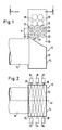
- Fig. 1 now shows schematically the end of a rotary kiln 10, which protrudes somewhat into the first beam train or boiler train 14 of a boiler, generally designated 12. Between the outer circumference of the rotary kiln 10 and the opening in the boiler train 14 there is an annular gap of e.g. 10 - 40 mm width available, which is not shown in Fig. 1 and enters the boiler 12 through the so-called secondary air.
- annular gap e.g. 10 - 40 mm width available, which is not shown in Fig. 1 and enters the boiler 12 through the so-called secondary air.
- the exhaust gases from the rotary kiln 10 flow vertically from bottom to top in the boiler train 14 and, according to the invention, they are mixed vigorously with each other and with the secondary air in the boiler train 14.
- Burners 16, 18, 20, 22, 24, 26, in particular so-called high-speed burners are therefore arranged above the entry end of the rotary kiln 10 into the boiler train 14, expediently directly above, and are mounted in the two opposite side walls 36, 38 of the boiler train 14 and installed.
- each side wall of the boiler train 14 e.g. the burners 16, 18, 20 in the side wall 38 and the burners 22, 24, 26 in the side wall 36 of the boiler train 14.
- the burners 16, 18, 20 thus lie opposite the burners 22, 24, 26 and the combustion gas jets emerging from their nozzles 30 are directed towards one another.
- the individual burners are vertically offset from one another in the vertical direction, for example the burners 16, 18, 20 can lie in one plane, while the burners 22, 24, 26 can lie in another higher plane.
- the burners 16 and 20 installed in the wall 38 lie in a horizontal plane, but the burner 18 arranged between the burners 16 and 20 lies in a higher plane.
- the burners 22, 24, 26, which are installed in the wall 36 of the boiler train 14, here the burners 22 and 26, as shown in FIG. 1, are in the upper level, while the burner 24, which is between the two burners 22, 26 is installed in the wall 36, is arranged in the lower level.
- Both the vertical and the horizontal section of the burners from one another can be selected depending on the jet cones 32 of the combustion gases emerging from the burner nozzles 30.
- the horizontal spacing of the burners from one another can now expediently be chosen such that the jet cones 32 just meet or overlap approximately in the central plane 40 of the boiler train 14.
- the central axes of the burner nozzles 30 (and thus the central axes of the jet cones 32) preferably run horizontally and at right angles to the respective side wall 36 or 38.
- these central axes of the burner nozzles 30 or the jet cone 32 can also be inclined upwards or downwards at an acute angle to the horizontal, and they can also have an angle deviating from 90 ° to form the respective side wall 36 or 38.
- the term “horizontal” refers to the fact that the boiler train 14 is arranged vertically and the exhaust gases from the rotary kiln 10 flow vertically from the bottom up).
- the burners 16-26 With this arrangement of the burners 16-26, the horizontal and vertical distances of which practically correspond to the jet diameter in the middle of the boiler train 14, very good mixing of the exhaust gas flowing from bottom to top in the boiler train 14 is already achieved, since this arrangement already results in a very large part of the cross-sectional area of the tank train is covered. Due to the mutual displacement of the individual burners, a frequent deflection of the exhaust gases flowing in the boiler train 14 is achieved, and thus the mixing and reaction is intensified.
- the burners are as close as possible, i.e. arranged immediately above the outlet of the rotary kiln 10, which ensures that the secondary air is sucked in at the highest possible temperature by the burner jets and the time for the reaction of the oxygen with the carbon monoxide is as long as possible.
- further burners 28 e.g. Provide two burners each in two further levels, which are installed in the same way as the burners 16-26.
- the burners 28 are expediently offset in the horizontal direction relative to the burners 22, 18, 26 by half their center distance.
- the burners themselves which are commercially available, can be operated with propane gas, for example.
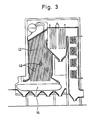
- FIG. 3 shows schematically a boiler, e.g. a power plant boiler that is operated with coal firing.
- the boiler 42 is designed and constructed in a manner known per se, so that it need not be described in more detail.
- a traveling grate 44 on which the furnace is located, and the hot exhaust gases or flue gases rise, as is also known, through the boiler 42 upwards.
- burners 46 are installed in at least one wall of the boiler 42 in the lower region of the boiler 42 in such a way that their combustion gases are blown into the boiler transversely to the direction of flow of the flue gases coming from the boiler's furnace, whereby the inflow speed of these combustion gases is about 100 m / s or more.
- the high-speed burners 46 are preferably installed in two opposite walls of the boiler 42 and their combustion gases flow into the boiler 42 facing one another.
- the high-speed burners 46 can lie in one plane, but they are advantageously arranged one above the other and offset from one another in at least two or more planes, as shown in FIG.
- the method according to the invention is also suitable for domestic waste incineration plants (not shown), which e.g. work with sloping grate firing, but sloping grate firing is also used for coal.
- the high-speed burners are also arranged above the furnace in the lower area of the boiler (or boiler train), as described above in connection with a power plant boiler.
Landscapes
- Engineering & Computer Science (AREA)
- Mechanical Engineering (AREA)
- General Engineering & Computer Science (AREA)
- Physics & Mathematics (AREA)
- Thermal Sciences (AREA)
- Incineration Of Waste (AREA)
- Muffle Furnaces And Rotary Kilns (AREA)
- Gasification And Melting Of Waste (AREA)
- Processing Of Solid Wastes (AREA)
Abstract
Description
- Die Erfindung betrifft ein Verfahren und eine Vorrichtung zur Reduzierung des CO-Gehaltes in Abgasen von Verbrennungsanlagen, insbesondere bei der Verbrennung von Haus- und Sondermüll, wobei der Müll z.B. in einem Drehrohrofen verbrannt und die Abgase durch einen dem Ofen nachgeschalteten Kesse geleitet werden. Kohlenmonoxid, dessen Anteil möglichst klein gehalten werden soll. So verlangt die TA Luft einen Kohlenmonoxidgehalt im Reingas von weniger als 100 mg/m³.
- Bei Müllverbrennungsanlagen beispielsweise wird der Müll in gleichstrombetriebene Drehrohröfen eingebracht und dort verbrannt.
- Diese Öfen enden in Abhitze-Kesseln, aus denen die Schlacke nach unten abgezogen wird, während die Abgase oder Rauchgase den ersten Kesselzug praktisch senkrecht von unten nach oben durchströmen. Nach einer Umlenkung erfolgt ein weiterer Wärmeaustausch in einem Konvektionsteil. Den Abhitzekesseln schließt sich ein Abgasreinigungsverfahren zur Enthalogenisierung, Entschwefelung und Entstaubung an.
- Die Sauerstoffgehalte im Kessel betragen etwa 10% und die Rauchgastemperaturen im unteren Bereich des ersten Kesselzuges liegen regelmäßig oberhalb (von 800°C. Der Sauerstoff stammt aus dem Drehrohrofen-Prozess und aus der sogenannten Sekundär-Luftzufuhr.
- Da diese Voraussetzung an sich einen guten Ausbrand hinsichtlich des CO-Gehaltes der Abgase ergeben sollte, wird angenommen, daß in dem Abgas eine Strähnenbildung auftritt und die Vermischung der Abgase mit dem Luftsauerstoff unzureichend ist.
- Der Erfindung liegt nun die Aufgabe zugrunde, den CO-Gehalt in den Abgasen von Verbrennungsanlagen zu reduzieren.
- Erfindungsgemäß wird dies dadurch erreicht, daß die Abgase im unteren Bereich des dem Ofen nachgeschalteten Abhitzekessels durchmischt werden, wozu vorzugsweise in den Kessel die Verbrennungsgase von Brennern, z.B. Hochgeschwindigkeitsbrennern, eingeblasen werden.
- Vorzugsweise werden die Verbrennungsgase der Brenner quer zur Strömungsrichtung der Abgase in den Kessel eingeblasen, wobei die Einströmgeschwindigkeit dieser Verbrennungsgase vorzugsweise bei etwa 100 m/s und mehr liegt.
- Vorteilhafterweise werden die Verbrennungsgase in mehreren unterschiedlichen Ebenen bzw. Höhen von gegenüberliegenden Seiten des Kessels aus in diesen eingeblasen.
- Eine geeignete Vorrichtung zur Durchführung dieses Verfahrens umfaßt eine Mehrzahl von Brennern, z.B. Hochgeschwindigkeitsbrennern, die insbesondere im ersten Kesselzug eingebaut sind und vorzugsweise unmittelbar oberhalb des Austrittes des Drehrohrofens in den Kessel angeordnet sind und deren Verbrennungsgas-Ausströmdüsen ins Innere des Kessels gerichtet sind.
- Die Brenner sind vorteilhafterweise in zwei sich gegenüberliegenden Wänden des Kessels und aufeinanderzugerichtet eingebaut, wobei die Brenner in mehreren vertikalen Ebenen übereinander angeordnet sind.
- Die Verbrennungsgas-Ausströmdüsen der Brenner verlaufen dabei im wesentlichen horizontal.
- Vorzugsweise sind die in den beiden Wänden des Kessels sich gegenüberliegend eingebauten Brenner höhenversetzt zueinander angeordnet, wobei zweckmäßigerweise auch die jeweils in einer Wand des Kessels eingebauten Brenner alternierend höhenversetzt zueinander angeordnet sind.
- Nach einer weiteren Ausgestaltung der Erfindung können im Kessel oberhalb dieser Brenner zusätzliche Brenner installiert sein, die horizontal zu den erstgenannten Brennern um deren halben Mittenabstand versetzt angeordnet sind.
- Eine beispielsweise Ausführungsform der Erfindung wird nachfolgend anhand der Zeichnung beschrieben, in der
- Fig. 1 schematisch das in den ersten Kesselzug eines Abhitzekessels hineinragende Ende eines Drehrohrofens zeigt.
- Fig. 2 zeigt einen Schnitt längs der Linie II-II von Fig. 1.
- Fig. 3 zeigt schematisch im Schnitt einen Kessel mit einer Kohlefeuerung.
- Die Temperaturen im ersten Strahlungszug des Kessels betragen direkt oberhalb des Drehrohrofenendes gegenwärtig etwa 1000°C - 1500°C, in der Mitte des Zuges etwa 750 - 850°C und am oberen Ende im Umlenkbereich des Zuges etwa 600 - 700°C. Diese Temperaturen schwanken abhängig von der Müllzusammensetzung, der Ofenfahrweise und dem Verschmutzungsgrad des Kessels.
- Diese Temperaturen lassen jedoch mechanische Umwälzeinrichtungen weitgehend unzweckmäßig erscheinen, insbesondere auch aus Gründen der Betriebssicherheit.
- Nach der Erfindung werden daher die Rauchgase mit Hilfe von Brennern, insbesondere Hochgeschwindigkeitsbrennern, durchgemischt.
- Unter Hochgeschwindigkeitsbrennern sind Brenner zu verstehen, bei denen die Verbrennung in einer am Brenner montierten Brennkammer erfolgt und die Verbrennungsgase durch eine Düse mit Geschwindigkeiten von 100 m/s und mehr in den Kessel bzw. Kesselzug einströmen.
- Durch den hohen Austrittsimpuls der aus den Brennern austretenden Verbrennungsgase werden die durch den Kessel strömenden Abgase oder Rauchgase angesaugt und kräftig durchgemischt, um eine möglichst weitgehende Reaktion von CO mit O₂ zu erreichen.
- Fig. 1 zeigt nun schematisch das Ende eines Drehrohrofens 10, das etwas in den ersten Strahlenzug oder Kesselzug 14 eines allgemein mit 12 bezeichneten Kessels hineinragt. Zwischen dem Außenumfang des Drehrohrofens 10 und der Öffnung im Kesselzug 14 ist ein Ringspalt von z.B. 10 - 40 mm Breite vorhanden, der in Fig. 1 jedoch nicht dargestellt ist und durch den sogenannte Sekundärluft in den Kessel 12 eintritt.
- Die Abgase aus dem Drehrohrofen 10 strömen im Kesselzug 14 vertikal von unten nach oben und sie werden im Kesselzug 14 erfindungsgemäß unter sich und mit der Sekundärluft kräftig durchgemischt.
- Oberhalb des Eintrittsendes des Drehrohrofens 10 in den Kesselzug 14, zweckmäßigerweise unmittelbar oberhalb, sind daher Brenner 16, 18, 20, 22, 24, 26, insbesondere sogenannte Hochgeschwindigkeitsbrenner, angeordnet, die in den beiden sich gegenüberliegenden Seitenwänden 36, 38 des Kesselzuges 14 montiert und installiert sind.
- Im dargestellten Beispiel sind in jeder Seitenwand des Kesselzuges 14 drei Brenner eingebaut, so z.B. die Brenner 16, 18, 20 in der Seitenwand 38 und die Brenner 22, 24, 26 in der Seitenwand 36 des Kesselzuges 14.
- Die Brenner 16, 18, 20 liegen somit den Brennern 22, 24, 26 gegenüber und die aus ihren Düsen 30 austretenden Verbrennungsgasstrahlen sind aufeinanderzugerichtet.
- In vertikaler Richtung sind die einzelnen Brenner höhenversetzt zueinander angeordnet, so können beispielsweise die Brenner 16, 18, 20 in einer Ebene liegen, während die Brenner 22, 24, 26 in einer anderen höheren Ebene liegen können.
- Es hat sich ferner gezeigt, daß es zweckmäßig ist, auch die Brenner, die an einer der beiden Wände 36 oder 38 installiert sind, höhenversetzt zueinander anzuordnen, wie Fig. 1 zeigt.
- So liegen die Brenner 16 und 20, die in der Wand 38 installiert sind, in einer horizontalen Ebene, der zwischen den Brennern 16 und 20 angeordnete Brenner 18 liegt jedoch in einer höheren Ebene. Entsprechendes gilt für die Brenner 22, 24, 26, die in der Wand 36 des Kesselzuges 14 installiert sind, wobei hier die Brenner 22 und 26, wie Fig. 1 zeigt, in der oberen Ebene liegen, während der Brenner 24, der zwischen den beiden Brennern 22, 26 in der Wand 36 eingebaut ist, in der unteren Ebene angeordnet ist.
- Sowohl der vertikale als auch der horizontale Abschnitt der Brenner voneinander kann abhängig von den Strahl kegeln 32 der aus den Brennerdüsen 30 austretenden Verbrennungsgase gewählt werden.
- Messungen haben ergeben, daß der Öffnungswinkel dieser Strahlkegel 32 etwa 20° beträgt.
- Der horizontale Abstand der Brenner voneinander kann nun zweckmäßigerweise so gewählt werden, daß sich die Strahlkegel 32 etwa in der Mittelebene 40 des Kesselzuges 14 gerade treffen bzw. überschneiden.
- Entsprechendes gilt für den vertikalen Abstand A der beiden Brennergruppen voneinander.
- Die Mittelachsen der Brennerdüsen 30 (und damit die Mittelachsen der Strahlkegel 32) verlaufen vorzugsweise horizontal und rechtwinklig zu der jeweiligen Seitenwand 36 bzw. 38.
- Es wird aber betont, daß dies nicht der Fall zu sein braucht, d.h. diese Mittelachsen der Brennerdüsen 30 bzw. der Strahlkegel 32 können auch in einem spitzen Winkel zur Horizontalen nach oben oder nach unten geneigt verlaufen, außerdem können sie einen von 90° abweichenden Winkel zur jeweiligen Seitenwand 36 bzw. 38 bilden. (Die Bezeichnung "horizontal" bezieht sich darauf, daß der Kesselzug 14 vertikal angeordnet ist und die Abgase aus dem Drehrohrofen 10 vertikal von unten nach oben strömen).
- Mit dieser Anordnung der Brenner 16 - 26, deren horizontaler und deren vertikaler Abstand praktisch dem Strahldurchmesser in der Mitte des Kesselzuges 14 entspricht, wird bereits eine sehr gute Durchmischung des im Kesselzug 14 von unten nach oben strömenden Abgases erzielt, da durch diese Anordnung bereits ein sehr großer Teil der Querschnittsfläche des Kesselzuges erfaßt ist. Durch die wechselseitige Versetzung der einzelnen Brenner wird eine häufige Umlenkung der im Kesselzug 14 aufströmenden Abgase erreicht und damit die Vermischung und Reaktion intensiviert. Vorzugsweise sind die Brenner möglichst nahe, d.h. unmittelbar oberhalb dem Austritt des Drehrohrofens 10 angeordnet, wodurch erreicht wird, daß die Sekundärluft bei möglichst hoher Temperatur von den Brennerstrahlen angesaugt wird und die Zeit für die Reaktion des Sauerstoffes mit dem Kohlenmonoxid möglichst lang ist.
- Darüber hinaus kann vorgesehen sein, oberhalb der Brenner 16 - 26 weitere Brenner 28, z.B. je zwei Brenner in zwei weiteren Ebenen, vorzusehen, die in derselben Weise eingebaut sind wie die Brenner 16 - 26. Die Brenner 28 sind zweckmäßigerweise jedoch in horizontaler Richtung relativ zu den Brennern 22, 18, 26 um deren halben Mittenabstand versetzt angeordnet.
- Durch diese zusätzlichen Brenner 28 können Abgas-Strähnen, die durch die unteren Brennergruppen noch nicht erfaßt worden sind, durchgemischt werden, wodurch die Reaktion von CO mit O₂ weiter verbessert wird.
- Die Brenner selbst, die handelsüblich käuflich sind, können beispielsweise mit Propangas betrieben werden.
- Figur 3 zeigt schematisch einen Kessel, z.B. einen Kraftwerks-Kessel, der mit Kohlefeuerung betrieben wird.
- Der Kessel 42 ist in an sich bekannter Weise ausgebildet und aufgebaut, so daß er nicht näher beschrieben zu werden braucht.
- Unterhalb des Kessels 42 befindet sich ein Wanderrost 44, auf dem sich die Feuerung befindet, und die heißen Abgase oder Rauchgase steigen, wie ebenfalls bekannt, durch den Kessel 42 hindurch nach oben.
- Oberhalb des Wanderrostes 44 sind im unteren Bereich des Kessels 42 Brenner 46, insbesondere Hochgeschwindigkeits-Brenner, in wenigstens eine Wand des Kessels 42 so eingebaut, daß ihre Verbrennungsgase quer zur Strömungsrichtung der von der Feuerung des Kessels kommenden Rauchgase in den Kessel eingeblasen werden, wobei die Einströmgeschwindigkeit dieser Verbrennungsgase bei etwa 100 m/s oder darüber liegt.
- Vorzugsweise sind die Hochgeschwindigkeitsbrenner 46 in zwei sich gegenüberliegenden Wänden des Kessels 42 eingebaut und ihre Verbrennungsgase strömen aufeinanderzugerichtet in den Kessel 42 ein. Die Hochgeschwindigkeitsbrenner 46 können in einer Ebene liegen, vorteilhafterweise sind sie aber in wenigstens zwei oder mehreren Ebenen übereinander und versetzt zueinander angeordnet, wie Figur 3 zeigt.
- Das erfindungsgemäße Verfahren eignet sich auch für Hausmüllverbrennungsanlagen (nicht dargestellt), die z.B. mit Schrägrostfeuerung arbeiten, wobei Schrägrostfeuerungen aber auch für Kohle eingesetzt werden.
- Hier sind die Hochgeschwindigkeitsbrenner ebenfalls oberhalb der Feuerung im unteren Bereich des Kessels (oder Kesselzuges) angeordnet, wie vorstehend in Verbindung mit einem Kraftwerks-Kessel beschrieben wurde.
Claims (16)
Priority Applications (1)
| Application Number | Priority Date | Filing Date | Title |
|---|---|---|---|
| AT89116364T ATE98357T1 (de) | 1988-11-23 | 1989-09-05 | Vorrichtung zur verbrennung von haus- und sondermuell. |
Applications Claiming Priority (2)
| Application Number | Priority Date | Filing Date | Title |
|---|---|---|---|
| DE3839503 | 1988-11-23 | ||
| DE3839503A DE3839503A1 (de) | 1988-11-23 | 1988-11-23 | Verfahren und vorrichtung zur reduzierung des co-gehaltes in abgasen von verbrennungsanlagen |
Publications (2)
| Publication Number | Publication Date |
|---|---|
| EP0370184A1 true EP0370184A1 (de) | 1990-05-30 |
| EP0370184B1 EP0370184B1 (de) | 1993-12-08 |
Family
ID=6367699
Family Applications (1)
| Application Number | Title | Priority Date | Filing Date |
|---|---|---|---|
| EP89116364A Expired - Lifetime EP0370184B1 (de) | 1988-11-23 | 1989-09-05 | Vorrichtung zur Verbrennung von Haus- und Sondermüll |
Country Status (4)
| Country | Link |
|---|---|
| EP (1) | EP0370184B1 (de) |
| AT (1) | ATE98357T1 (de) |
| CA (1) | CA1337161C (de) |
| DE (2) | DE3839503A1 (de) |
Citations (2)
| Publication number | Priority date | Publication date | Assignee | Title |
|---|---|---|---|---|
| US4162686A (en) * | 1977-10-17 | 1979-07-31 | North American Manufacturing Company | Industrial boiler utilizing multiple fuels and having reduced particulate emission and method of combustion |
| EP0044063A1 (de) * | 1980-07-12 | 1982-01-20 | Dieter Popp | Heissgaserzeuger |
Family Cites Families (10)
| Publication number | Priority date | Publication date | Assignee | Title |
|---|---|---|---|---|
| US3043279A (en) * | 1954-06-18 | 1962-07-10 | Svenska Maskinverken Ab | Steam boiler plant |
| DE1289938B (de) * | 1966-03-26 | 1969-02-27 | Duerrwerke Ag | Mit einem kohlenstaubbeheizten Dampferzeuger fuer hoechste Druecke und Temperaturen kombinierte Muellverbrennungsanlage |
| DE1947164A1 (de) * | 1969-09-18 | 1971-03-25 | Koppers Wistra Ofenbau Gmbh | Muellverbrennungsanlage |
| CH583881A5 (de) * | 1975-07-04 | 1977-01-14 | Von Roll Ag | |
| DE3444480A1 (de) * | 1984-12-06 | 1986-06-12 | Maschinenfabrik A. Lambion, 3548 Arolsen | Feuerung fuer stueckige abfallstoffe |
| FR2580057B1 (de) * | 1985-04-05 | 1990-01-05 | Mediterranee Const Navales Ind | |
| DE3625397A1 (de) * | 1986-07-26 | 1988-02-04 | Gutehoffnungshuette Man | Nachbrennkammer hinter einem verbrennungsofen einer verbrennungseinrichtung fuer chemischen abfall |
| WO1988002834A1 (en) * | 1986-10-11 | 1988-04-21 | Erithglen Limited | Furnace |
| US4724778A (en) * | 1986-12-15 | 1988-02-16 | Westinghouse Electric Corp. | Air control for combustor |
| DE3703855A1 (de) * | 1987-02-07 | 1988-08-18 | Gutehoffnungshuette Man | Verbrennungsanlage fuer abfallstoffe |
-
1988
- 1988-11-23 DE DE3839503A patent/DE3839503A1/de not_active Withdrawn
-
1989
- 1989-09-05 AT AT89116364T patent/ATE98357T1/de not_active IP Right Cessation
- 1989-09-05 DE DE89116364T patent/DE58906375D1/de not_active Expired - Fee Related
- 1989-09-05 EP EP89116364A patent/EP0370184B1/de not_active Expired - Lifetime
- 1989-09-29 CA CA000615143A patent/CA1337161C/en not_active Expired - Fee Related
Patent Citations (2)
| Publication number | Priority date | Publication date | Assignee | Title |
|---|---|---|---|---|
| US4162686A (en) * | 1977-10-17 | 1979-07-31 | North American Manufacturing Company | Industrial boiler utilizing multiple fuels and having reduced particulate emission and method of combustion |
| EP0044063A1 (de) * | 1980-07-12 | 1982-01-20 | Dieter Popp | Heissgaserzeuger |
Also Published As
| Publication number | Publication date |
|---|---|
| EP0370184B1 (de) | 1993-12-08 |
| ATE98357T1 (de) | 1993-12-15 |
| DE3839503A1 (de) | 1990-05-31 |
| CA1337161C (en) | 1995-10-03 |
| DE58906375D1 (de) | 1994-01-20 |
Similar Documents
| Publication | Publication Date | Title |
|---|---|---|
| DE2425962C3 (de) | Gasgenerator für die Vergasung feinzerteilter Brennstoffe | |
| DE3038875C2 (de) | Müllverbrennungsanlage | |
| DE2621496C3 (de) | Brenner für einen Hochofen-Winderhitzer | |
| DE3722523C1 (en) | Furnace with nozzles for blowing in ammonia for selective noncatalytic flue gas denitration (SNCR) | |
| EP0204176A2 (de) | Brennkammer für eine Wirbelschichtfeuerung | |
| DE3716088A1 (de) | Verfahren zum verbrennen insbesondere von muell | |
| EP0616022B1 (de) | Verfahren für die Druckvergasung von feinteiligen Brennstoffen | |
| DE2908448A1 (de) | Brenner | |
| DE69207802T2 (de) | Müllverbrennungsofen | |
| DE1178767B (de) | Verfahren zur Beheizung von Brennoefen der Grobkeramik und Brennofen mit Vorrichtung zur Durchfuehrung dieses Verfahrens | |
| DE19731474C1 (de) | Verfahren zum Betrieb eines Eckenbrenners für eine Tangentialfeuerung und Eckenbrenner zur Durchführung des Verfahrens | |
| DE2449798C2 (de) | Wirbelschichtofen für die Verbrennung von teilweise entwässertem Schlamm | |
| EP0577881A1 (de) | Regenerative Schmelzwanne mit verminderter NOx-Bildung | |
| EP0370184A1 (de) | Vorrichtung zur Verbrennung von Haus- und Sondermüll | |
| DD296619A5 (de) | Verfahren und vorrichtung zur reduzierung des co-gehaltes in abgasen von verbrennungsanlagen | |
| EP2426414B1 (de) | Verfahren und Vorrichtung zum Verbrennen fester Brennstoffe | |
| DE102007044043A1 (de) | Glasschmelzanlage und Verfahren zum Betrieb | |
| DE3406989C2 (de) | Verfahren und Vorrichtung zur Entschwefelung heißer, schadstoffhaltiger Abgase mit Wärmerückgewinnung | |
| DE8814604U1 (de) | Vorrichtung zur Reduzierung des CO-Gehaltes in Abgasen von Verbrennungsanlagen | |
| DE224565C (de) | ||
| DE3625397C2 (de) | ||
| EP2085693A2 (de) | Verfahren und Vorrichtung zum Verbrennen fester Brennstoffe | |
| DE4436728A1 (de) | Verfahren und Vorrichtung für eine schadstoffarme gestufte Verbrennung | |
| DE19541178C2 (de) | Verfahren zum Verbrennen von staubförmigem Brennstoff, insbesondere Braunkohle, in einem Feuerraum | |
| DE3206409A1 (de) | Wasserrohrkessel mit rauschgasentschwefelung |
Legal Events
| Date | Code | Title | Description |
|---|---|---|---|
| PUAI | Public reference made under article 153(3) epc to a published international application that has entered the european phase |
Free format text: ORIGINAL CODE: 0009012 |
|
| AK | Designated contracting states |
Kind code of ref document: A1 Designated state(s): AT BE CH DE FR GB LI NL SE |
|
| 17P | Request for examination filed |
Effective date: 19900928 |
|
| 17Q | First examination report despatched |
Effective date: 19911219 |
|
| GRAA | (expected) grant |
Free format text: ORIGINAL CODE: 0009210 |
|
| AK | Designated contracting states |
Kind code of ref document: B1 Designated state(s): AT BE CH DE FR GB LI NL SE |
|
| REF | Corresponds to: |
Ref document number: 98357 Country of ref document: AT Date of ref document: 19931215 Kind code of ref document: T |
|
| ET | Fr: translation filed | ||
| GBT | Gb: translation of ep patent filed (gb section 77(6)(a)/1977) |
Effective date: 19931220 |
|
| REF | Corresponds to: |
Ref document number: 58906375 Country of ref document: DE Date of ref document: 19940120 |
|
| PLBE | No opposition filed within time limit |
Free format text: ORIGINAL CODE: 0009261 |
|
| STAA | Information on the status of an ep patent application or granted ep patent |
Free format text: STATUS: NO OPPOSITION FILED WITHIN TIME LIMIT |
|
| 26N | No opposition filed | ||
| EAL | Se: european patent in force in sweden |
Ref document number: 89116364.4 |
|
| PGFP | Annual fee paid to national office [announced via postgrant information from national office to epo] |
Ref country code: GB Payment date: 19980824 Year of fee payment: 10 |
|
| PGFP | Annual fee paid to national office [announced via postgrant information from national office to epo] |
Ref country code: FR Payment date: 19980917 Year of fee payment: 10 |
|
| PGFP | Annual fee paid to national office [announced via postgrant information from national office to epo] |
Ref country code: SE Payment date: 19980922 Year of fee payment: 10 Ref country code: BE Payment date: 19980922 Year of fee payment: 10 Ref country code: AT Payment date: 19980922 Year of fee payment: 10 |
|
| PGFP | Annual fee paid to national office [announced via postgrant information from national office to epo] |
Ref country code: DE Payment date: 19980925 Year of fee payment: 10 |
|
| PGFP | Annual fee paid to national office [announced via postgrant information from national office to epo] |
Ref country code: CH Payment date: 19980929 Year of fee payment: 10 |
|
| PGFP | Annual fee paid to national office [announced via postgrant information from national office to epo] |
Ref country code: NL Payment date: 19980930 Year of fee payment: 10 |
|
| PG25 | Lapsed in a contracting state [announced via postgrant information from national office to epo] |
Ref country code: GB Free format text: LAPSE BECAUSE OF NON-PAYMENT OF DUE FEES Effective date: 19990905 Ref country code: AT Free format text: LAPSE BECAUSE OF NON-PAYMENT OF DUE FEES Effective date: 19990905 |
|
| PG25 | Lapsed in a contracting state [announced via postgrant information from national office to epo] |
Ref country code: SE Free format text: THE PATENT HAS BEEN ANNULLED BY A DECISION OF A NATIONAL AUTHORITY Effective date: 19990929 |
|
| PG25 | Lapsed in a contracting state [announced via postgrant information from national office to epo] |
Ref country code: LI Free format text: LAPSE BECAUSE OF NON-PAYMENT OF DUE FEES Effective date: 19990930 Ref country code: CH Free format text: LAPSE BECAUSE OF NON-PAYMENT OF DUE FEES Effective date: 19990930 Ref country code: BE Free format text: LAPSE BECAUSE OF NON-PAYMENT OF DUE FEES Effective date: 19990930 |
|
| BERE | Be: lapsed |
Owner name: ABFALL-VERWERTUNGS-G.M.B.H. & CO. K.G. AVG Effective date: 19990930 |
|
| PG25 | Lapsed in a contracting state [announced via postgrant information from national office to epo] |
Ref country code: NL Free format text: LAPSE BECAUSE OF NON-PAYMENT OF DUE FEES Effective date: 20000401 |
|
| GBPC | Gb: european patent ceased through non-payment of renewal fee |
Effective date: 19990905 |
|
| EUG | Se: european patent has lapsed |
Ref document number: 89116364.4 |
|
| REG | Reference to a national code |
Ref country code: CH Ref legal event code: PL |
|
| PG25 | Lapsed in a contracting state [announced via postgrant information from national office to epo] |
Ref country code: FR Free format text: LAPSE BECAUSE OF NON-PAYMENT OF DUE FEES Effective date: 20000531 |
|
| NLV4 | Nl: lapsed or anulled due to non-payment of the annual fee |
Effective date: 20000401 |
|
| PG25 | Lapsed in a contracting state [announced via postgrant information from national office to epo] |
Ref country code: DE Free format text: LAPSE BECAUSE OF NON-PAYMENT OF DUE FEES Effective date: 20000701 |
|
| REG | Reference to a national code |
Ref country code: FR Ref legal event code: ST |