EP0368300B1 - Vorrichtung zum Einstellen der Giessbetriebsbedingungen in einer Spritzgiessmaschine - Google Patents
Vorrichtung zum Einstellen der Giessbetriebsbedingungen in einer Spritzgiessmaschine Download PDFInfo
- Publication number
- EP0368300B1 EP0368300B1 EP89120743A EP89120743A EP0368300B1 EP 0368300 B1 EP0368300 B1 EP 0368300B1 EP 89120743 A EP89120743 A EP 89120743A EP 89120743 A EP89120743 A EP 89120743A EP 0368300 B1 EP0368300 B1 EP 0368300B1
- Authority
- EP
- European Patent Office
- Prior art keywords
- defect
- molding
- injection molding
- molding machine
- evaluating
- Prior art date
- Legal status (The legal status is an assumption and is not a legal conclusion. Google has not performed a legal analysis and makes no representation as to the accuracy of the status listed.)
- Expired - Lifetime
Links
Images


Classifications
-
- B—PERFORMING OPERATIONS; TRANSPORTING
- B29—WORKING OF PLASTICS; WORKING OF SUBSTANCES IN A PLASTIC STATE IN GENERAL
- B29C—SHAPING OR JOINING OF PLASTICS; SHAPING OF MATERIAL IN A PLASTIC STATE, NOT OTHERWISE PROVIDED FOR; AFTER-TREATMENT OF THE SHAPED PRODUCTS, e.g. REPAIRING
- B29C45/00—Injection moulding, i.e. forcing the required volume of moulding material through a nozzle into a closed mould; Apparatus therefor
- B29C45/17—Component parts, details or accessories; Auxiliary operations
- B29C45/76—Measuring, controlling or regulating
- B29C45/768—Detecting defective moulding conditions
-
- B—PERFORMING OPERATIONS; TRANSPORTING
- B29—WORKING OF PLASTICS; WORKING OF SUBSTANCES IN A PLASTIC STATE IN GENERAL
- B29C—SHAPING OR JOINING OF PLASTICS; SHAPING OF MATERIAL IN A PLASTIC STATE, NOT OTHERWISE PROVIDED FOR; AFTER-TREATMENT OF THE SHAPED PRODUCTS, e.g. REPAIRING
- B29C45/00—Injection moulding, i.e. forcing the required volume of moulding material through a nozzle into a closed mould; Apparatus therefor
- B29C45/17—Component parts, details or accessories; Auxiliary operations
- B29C45/76—Measuring, controlling or regulating
- B29C45/766—Measuring, controlling or regulating the setting or resetting of moulding conditions, e.g. before starting a cycle
-
- B—PERFORMING OPERATIONS; TRANSPORTING
- B29—WORKING OF PLASTICS; WORKING OF SUBSTANCES IN A PLASTIC STATE IN GENERAL
- B29C—SHAPING OR JOINING OF PLASTICS; SHAPING OF MATERIAL IN A PLASTIC STATE, NOT OTHERWISE PROVIDED FOR; AFTER-TREATMENT OF THE SHAPED PRODUCTS, e.g. REPAIRING
- B29C45/00—Injection moulding, i.e. forcing the required volume of moulding material through a nozzle into a closed mould; Apparatus therefor
- B29C45/0025—Preventing defects on the moulded article, e.g. weld lines, shrinkage marks
Definitions
- This invention relates to an apparatus for setting molding conditions in an injection molding machine in accordance with the preamble of claim 1.
- a molding condition setting system for an injection molding machine which is capable of efficiently and accurately setting an optimum molding condition into the injection molding machine in order to obtain a predetermined quality of molded products upon molding a molten material such as resin and the like.
- JP-A-63-209917 An apparatus as defined in the preamble of claim 1 is disclosed in JP-A-63-209917.
- This prior art apparatus comprises means for inputting the bad phenomena and degree of influence of the cause of failure to the bad phenomena, a knowledge base storing a data of the bad phenomena and a data of diagnosis rules and an inference section infering the degree of influence of the cause of failure to the bad phenomena.
- This apparatus suffers from the disadvantage that it is difficult to determine an initial molding condition and a desired molding condition for a new model since no molten material flow analysis is applied.
- JP-A-63-209918 discloses to provide a data base and/or a knowledge base storing the optimum molding condition of a mold in the memory, and to search and infer the optimum molding condition of a mold from the data base and/or the knowledge base.
- EP-A-0 377 736 which is a document according to Art.
- 54(3) EPC discloses a controller for deducing optimum countermeasures in case the object to be controlled or the product becomes defective, particularly suitable for setting and controlling the operation conditions of an injection molding machine.
- the controller has an input unit, for defect conditions, a memory storing defect conditions, causes of defect conditions, and proposed countermeasures for the causes; evaluation means for putting the countermeasures in a priority order based on the contents of the memory and conditions of the object to be controlled, predicting another possible defect resulting from the countermeasure taken, and deducing an optimum countermeasure; and a display for displaying the proposed countermeasures.
- the control operation is carried out in accordance with either the proposed optimum countermeasure or one of the proposed countermeasures that is selected by an operator from those on the display screen.
- the object of the present invention is to provide a superior molding condition setting system for an injection molding machine such that the skillful engineer's know-how is built as an intelligent data base which is introduced into the computer.
- the system even an unskilled engineer shall be in a position to easily set the optimum molding condition as well as the skillful engineer does.
- an apparatus for setting molding conditions in an injection molding machine comprising: means for analyzing a flow of a molten material, which carries out analyses of a resin flow, a resin cooling and a structure/strength of a molded product by using a model mold being designed on a computer; means for evaluating a analysis result, which determines an initial molding condition to be actually set in an injection molding machine on the basis of the analysis result being obtained by the molten material flow analysis means and provides a permissible range of a molding condition and data of an average thickness and a thin or thick part of the molded product; means for eliminating a molding defect, which infers causes of a molding defect in accordance with a relation between a deficiency of the molded product and a condition of a resin, mold, etc., stores both the first intelligent data base for inferring the cause of the molding defect and the second intelligent data base for evaluating measures to be taken, and calculates a correction value of the molding condition after selecting the effective measures
- the analysis result evaluation means compares the correction values of the molding conditions such as a mold temperature, a resin temperature, an injection speed, a cool time, etc. being obtained by the molding defect elimination means, with permissible values being obtained by the molten material flow analysis means.
- An alarm message can be issued and/or the value of the molding condition can be corrected again when the correction value of the molding condition exceeds the permissible value.
- Data of a configuration of the model mold which are employed for the analysis by the molten material flow analysis means can be used by the molding defect elimination means .
- the corrected value of the molding condition being obtained by the molding defect elimination means can be analyzed by the molten material flow analysis means, evaluated by the analysis result evaluation means and then set in the injection molding machine.
- This system may be preferably connected to the injection molding machine via a communication line so as to automate both a transfer of data regarding the molding defect and a setting of the molding condition.
- system may be provided with an IC card capable of writing the molding condition and/or an operating state of the injection molding machine so that various data can be interchanged between the system and the injection molding machine.
- the optimum molding condition setting system for the injection molding machine comprising the molten material flow analysis means for analyzing the resin flow, the resin cooling and the structure/strength of molded products by using the designed model mold.
- the system also comprises the analysis result evaluation means for determining an initial molding condition and its permissible range in accordance with the analysis result.
- the initial molding condition is set into the injection molding machine and a test shot is carried out in order to check for the deficiency of the molded product. If the deficiency of the molded product has found out, the data of the deficiency is entered into the molding defect elimination means.
- a cause of the molding defect can be inferred and a measure to the cause can be obtained with high efficiency and accuracy. Consequently, the molding condition can properly and immediately be corrected in accordance with data obtained by the molten material flow analysis means.
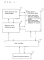
- FIG. 1 shows a system for setting an optimum molding condition for an injection molding machine according to an embodiment of the invention.
- the system shown in FIG. 1 is constituted such that the optimum molding condition and a control program thereunder can be prepared for and entered into a control unit of the injection molding machine (10). Therefore, the system includes a molten material flow analysis means 12, an analysis result evaluation means 14, a molding defect elimination means 16 and a user interface 18. These components are connected to the injection molding machine 10 via the user interface 18, resulting in configuring a man-machine system.
- the molten material flow analysis means 12 designs a model mold at first.
- configuration data such as, for example, a projection area, thickness, a gate shape and runner shape of the mold and the like are determined.
- a function of distributions of a resin temperature and resin pressure relative to all the elements of the model mold is obtained by using as a variable a filling time or a mold temperature while a filling pattern diagram is designed.
- an elapsed time relative to a resin flow in the mold is represented by a parameter so that which part of the molded product is produced during the filling process of the mold can be identified. Therefore, it is possible to analyze a defective part in a filling control process in the injection molding machine when entering the data of the deficiency of the molded product into the filling pattern diagram.
- a function showing a characteristic of a molten resin temperature is obtained from an arithmetic operation result of the distribution of the resin temperature at the end of a filling operation.
- Maximum and minimum resin temperatures (T) in all the elements of the model mold are represented by the functions having as a variable the filling time (t), respectively (T-t graph).
- a function showing a characteristic of the maximum resin pressure is obtained from an arithmetic operation result of the distribution of the resin pressure at the end of a filling operation relative to the obtained molten resin temperature.
- the maximum resin pressure (P) in all the elements of the model mold is represented by a function having both the filling time (t) as a variable and the resin temperature as a parameter at the start of the filling operation (P-t graph). Therefore, it is possible to determine a permissible range of the filling time which meets requirements according to a specification of the molding machine and in which the maximum resin pressure is stable to a variation of the filling time.
- the maximum resin pressure (P) in all the elements of the model mold is represented by a function having both a mold temperature (Tm) as a variable and the resin temperature as a parameter at the start of the filling operation (P-Tm graph). Therefore, it is possible to determine a permissible range of the mold temperature in which the maximum resin pressure is stable to a variation of the mold temperature.
- an analysis of a resin flow in the designed model mold is carried out to set a molding condition and a thickness, gate, runner, etc. of the mold. Subsequently, an analysis of a resin cooling is carried out to set a cool time and then an analysis of a structure/strength of a molded product is carried out to check for the structure and strength thereof and possibility of occurrence of a sink mark. If any problem is found out from the analysis results, these analysis are carried out again under other suitable conditions.
- An analysis result evaluation means 14 evaluates a thickness, gate, runner, etc. of the mold and the molding condition which are set in accordance with the analysis results being obtained by the molten material flow analysis means 12.
- the evaluation means also determines the cool time and evaluates the structure, strength, etc. of the molded product so as to make an initial molding condition to be actually set in the injection molding machine 10.
- the evaluation means builds data relative to an average thickness, a thin and thick part, etc. of the molded product while determining a permissible range of the molding condition.
- the initial molding condition being determined in such a way is set in the injection molding machine 10 so that a test shot is carried out.
- a molding defect elimination means 16 stores the first intelligent data base for inferring causes of a molding defect.
- the first intelligent data base includes measures being enumerated with a priority as well as the causes of the molding defect being inferred in accordance with a relation between a deficiency of a molded product and a condition of a resin and mold, etc. Accordingly, this intelligent data base can be set as shown in Table 1 of FIG. 2.
- a list of causes to be inferred is built in order to make an inference of the causes on the basis of actual data such as the deficiency of the molded product, the molding condition, an operating state of the injection molding machine (an amount of a cushion which is the resin remaining at the tip of a screw, an operation of the screw, etc.) and the like (refer to Table 2 of FIG. 3).
- a plurality of the causes for one defect namely occurrence of one defect is not limited to only one cause, a plurality of the causes may be usually inferred.
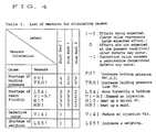
- a plurality of the inferred causes leads to a built-up of a list including a plurality of measures to be taken to eliminate the inferred causes (refer to Table 3 of FIG. 4).
- any measure for one defect is not always effective to other defects and may occasionally accelerate the defective state. For this reason, a degree of an effect of the measure as well as the defect which may be caused by selecting the measure are enumerated in the respective lists.
- the molding defect elimination means In addition to the first intelligent database in which the measures for elimination of the defect and the effects thereof are inferred, the molding defect elimination means also stores the second intelligent data base which is capable of evaluating the measures and converting the respective measures to an actual amount of operating conditions or factors of the injection molding machine. The priority of the measures for the molding defects is determined based on both the list of causes to be inferred and the list of measures to be taken.
- the second intelligent data base is applied to the measure having the highest priority as determined above in order that a correction value of the molding condition can be obtained.
- the molding condition is altered.
- the corrected molding condition is checked about whether it does not exceed a permissible range being determined by the analysis result evaluation means 14. If it exceeds the permissible range, the measure having the second priority is selected and the above mentioned operations are repeated.
- the properly corrected molding condition is determined and set in the injection molding machine 10. The test shot is carried out again, so that it is realized to decrease or eliminate the defect of the molded product.
- a user interface 18 is provided such that the system according to the present invention can be effectively operated in order to smoothly perform the specified control operations of the respective means 12, 14 and 16 by connecting these means to the injection molding machine 10 to be installed by a user.
- FIG. 5 is a flow chart showing a control program according to an embodiment of the invention for setting an optimum molding condition for the injection molding machine comprising a system shown in FIG. 1. Then, setting procedures of the optimum molding condition according to the system of the present invention are described hereinafter with reference to FIG. 5.
- the molten material flow analysis means 12 designs a model mold and successively carries out the above mentioned analyses of a resin flow, a resin cooling and a structure/strength of the model.
- the obtained results of these analyses are evaluated by the analysis result evaluation means 14 so that the initial molding condition and its permissible range are determined.
- the molding condition being determined is set in the injection molding machine 10 through the user interface 18. In this case, there are provided the following ways to set the molding condition in the injection molding machine 10:
- the test shot is carried out under the molding condition being set.
- the operator evaluates the molded product which is obtained after the test shot.
- a name and data of the deficiency are entered into the molding defect elimination means 16.
- the molding defect elimination means 16 For entering the data into the molding defect elimination means 16, there are provided the following ways as described above:
- the continuous manufacturing of the product can be immediately started without changing the molding condition.
- a defective portion is indicated in a filling pattern diagram being obtained by the molten material flow analysis means 12.
- the analysis result evaluation means 14 judges a defective portion which occurs during a filling process (the end or the midway of a resin flow, and if in the midway thereof, step No. among all the steps of a filling speed) and enters the result of the judgment into the molding defect elimination means 16.
- the molding defect elimination means 16 infers causes of the defect by using the first intelligent data base for inferring causes of the molding defect, in accordance with actual data such as the entered defective state, the molding condition (an evaluation, judgment, etc. by the analysis result evaluation means 14), an operating state of the injection molding machine (an amount of a cushion, an operation of the screw, etc.) and the like.
- the molding defect is a short shot which occurs at the molded product portion with an even thickness and at the end of the resin flow without formation of reduced area in the midway of the resin flow, and has an cushion amount ranging from 1mm to LS4 (a holding-pressure changing position) and a holding pressure upon TRI OUT (completion of injection time)
- the molding defect is caused by a fluidity of the resin and is evaluated as the rating 3 (three) for the possibility (refer to FIG. 2).
- the list of causes to be inferred is built as shown in FIG. 3. Since there is a plurality of the causes for one defect, a plurality of the causes may be usually inferred.
- a list of measures is built as shown in FIG. 4.
- a certain measure selected for to one defect is not necessarily effective to other defects and may occasionally accelerate the defective state.
- a degree of an effect of the measure as well as the defect which may occur by selecting the measure should be described in both the lists of causes to be inferred and measures to be taken.
- numerical values in Table 3 of FIG. 4 represent the effects of measures upon the elimination of the molding defects. The larger value represents that the more excellent effect is expected. Based on the degree of the effect, the value "0" is set when no effect is expected and the value "-" is set when the defect may occur.
- the measure with the highest priority is selected, and the correction value of the molding condition is calculated by using the second intelligent data base for evaluating measures.
- the correction value is checked about whether it does not exceed a permissible range being determined by the molten material flow analysis means 12 and the analysis result evaluation means 14. If it exceeds the permissible range, the measure having the second priority is selected to correct the molding condition again. If it does not exceed that range, the correction value of the molding condition is entered into the injection molding machine 10 with the correction to carry out the test shot. If a complete product is molded in the test shot process, the continuous manufacturing of the product can be immediately started without changing the molding condition.
- the test shot is carried out under the initial molding condition being obtained by the molten material flow analysis means so as to infer the causes of the defect of the molded product and take its appropriate measures.
- an accurate correction of the molding condition is executed, so that a setting of the proper molding condition for complete products can be achieved easily and in a short time.
- the permissible range of the molding condition is obtained from the analysis executed by the molten material flow analysis means and thereby the molding condition is capable of being corrected within a proper range. Accordingly, it is possible to eliminate an unnecessary and unuseful test shot.
Landscapes
- Engineering & Computer Science (AREA)
- Manufacturing & Machinery (AREA)
- Mechanical Engineering (AREA)
- Injection Moulding Of Plastics Or The Like (AREA)
Claims (8)
- Vorrichtung zum Einstellen einer Gießbetriebsbedingung in einer Spritzgießmaschine, umfassend:
ein Mittel (12) zum Analysieren eines Flusses von geschmolzenem Material innerhalb einer Modellgußform, wobei das Analysemittel (12) eine Abkühlung des Kunststoffflusses und eine Strukturfestigkeit eines gespritzten Erzeugnisses abschätzt, die von dem Fluß innerhalb der Modellgußform resultiert;
ein Datenbasismittel zum Ableiten von Ursachen eines eingegebenen Gießfehlers in Übereinstimmung mit einer Relation zwischen dem Gießfehler und einer Gußform oder eines Kunststoffzustandes, und
Schnittstellenmittel (18) zum Empfangen von Daten, die Fehler in gespritzten Erzeugnissen anzeigen, die in einer Spritzgießmaschine (10) hergestellt wurden, und zum Übertragen der Daten an das Analysemittel (12), wobei das Schnittstellenmittel (18) die Anfangsgießbetriebsbedingung von dem Analysemittel (12) empfängt und die Anfangsgießbetriebsbedingung an die Spritzgießmaschine (10) überträgt;
gekennzeichnet durch:
Mittel (14) zum Auswerten von Ergebnissen, die durch die Analysemittel (12) erzeugt worden sind, wobei die Auswertemittel (14) eine in einer Spritzgießmaschine (10) einzustellende Anfangsgießbetriebsbedingung bestimmen, die auf den Ergebnissen des Analysemittels (12) basieren, wobei das Auswertemittel (14) weiterhin einen Betriebsbereich der Gießbetriebsbedingung zur Verfügung stellt, sowie Daten, die eine durchschnittliche Dicke eines vorbestimmten Teiles des gespritzten Erzeugnisses anzeigen; und
Mittel (16) zum Beseitigen eines Gießfehlers, das eine erste Datenbasis zum Ableiten von Ursachen eines eingegebenen Gießfehlers in Übereinstimmung mit einer Relation zwischen dem Gießfehler und einer Gußform oder eines Kunststoffzustandes umfaßt, und das eine zweite Datenbasis zum Berechnen eines in die Spritzgießmaschine (10) einzugebenden Korrekturwertes umfaßt, wobei der Korrekturwert auf den Ursachen des Gießfehlers basiert, die durch die erste Datenbasis abgeleitet worden sind, wobei die erste Datenbasis mit Prioritäten versehene Korrekturmaßnahmen beinhaltet, die einem Bereich von möglichen Gießfehlern entsprechen, die in das Mittel zur Fehlerbeseitigung (16) eingegeben werden müssen, und wobei die zweite intelligente Datenbasis angepaßt wird, um die Korrekturmaßnahmen in den Korrekturwert umzuwandeln; bei dem das Schnittstellenmittel (18) die empfangenen Daten an das Mittel zur Fehlerbeseitigung (16) und an das Auswertemittel (14) überträgt, wobei das Schnittstellenmittel (18) die Anfangsgießbetriebsbedingung von dem Auswertemittel (14) empfängt und die Anfangsgießbetriebsbedingung an die Spritzgießmaschine (10) überträgt; und wobei das Auswertemittel (14) die Anfangsgießbetriebsbedingung in Übereinstimmung mit dem vom Mittel zur Fehlerbeseitigung (16) empfangenen Korrekturwert zurücksetzt, und das Schnittstellenmittel (18) einen zurückgesetzten Korrekturwert von dem Auswertemittel (14) empfängt und den zurückgesetzten Korrekturwert an die Spritzgießmaschine (10) überträgt. - Vorrichtung nach Anspruch 1, bei dem das Analysemittel (12) angepaßt ist, um ein Einspritzfolgediagramm zu generieren, das auf dem Kunststofffluß innerhalb der Modellgußform basiert, und bei dem Daten eines Fehlerpunktes in einem gespritzten Erzeugnis, die von dem Schnittstellenmittel (18) empfangen worden sind, in das Einspritzfolgediagramm eingegeben werden, um einen Fehler, der während der Einspritzung in der Spritzgießmaschine (10) auftritt, zu analysieren.
- Vorrichtung nach Anspruch 1, bei der das Auswertemittel (14) angepaßt ist, um eine Warnmeldung zu generieren, sobald der durch das Mittel zur Fehlerbeseitigung (16) generierte Korrekturwert sich außerhalb des Betriebsbereiches befindet, der durch das Auswertemittel (14) generiert wurde.
- Vorrichtung nach Anspruch 1, bei der das Auswertemittel (16) angepaßt ist, um den durch das Mittel zur Fehlerbeseitigung (16) generierten Korrekturwert zu ändern, sobald der durch das Mittel zur Fehlerbeseitigung (16) generierte Korrekturwert sich außerhalb des Betriebsbereiches befindet, der durch das Auswertemittel (14) generiert wurde.
- Vorrichtung nach Anspruch 1, bei der Daten, die eine Konfiguration der Modellgußform in dem Analysemittel (12) darstellen, ebenfalls durch das Mittel zur Fehlerbeseitigung (16) verwendet werden, um Ursachen eines Fehlers in einem gespritzten Erzeugnis abzuleiten.
- Vorrichtung nach Anspruch 1, bei der der durch das Mittel zur Fehlerbeseitigung (16) generierten Korrekturwert von dem Analysemittel (12) verwendet wird, um den Kunststofffluß innerhalb der Modellgußform erneut zu analysieren.
- Vorrichtung nach Anspruch 1, bei der das Schnittstellenmittel (18) eine Verbindungsleitung umfaßt, die eine Datenübertragung zwischen dem Mittel zur Fehlerbeseitigung (16), dem Auswertemittel (14) und der Spritzgießmaschine (10) ermöglicht.
- Vorrichtung nach Anspruch 1, bei der das Schnittstellenmittel (18) eine Leiterplatte mit integrierten Schaltkreisen umfaßt, für das Schreiben einer durch das Auswertemittel (14) generierten Gießbetriebsbedingung, sowie für das Schreiben eines Betriebszustandes der Spritzgießmaschine (10).
Applications Claiming Priority (2)
| Application Number | Priority Date | Filing Date | Title |
|---|---|---|---|
| JP63283084A JPH0720651B2 (ja) | 1988-11-09 | 1988-11-09 | 射出成形機の最適成形条件設定システム |
| JP283084/88 | 1988-11-09 |
Publications (3)
| Publication Number | Publication Date |
|---|---|
| EP0368300A2 EP0368300A2 (de) | 1990-05-16 |
| EP0368300A3 EP0368300A3 (de) | 1991-07-17 |
| EP0368300B1 true EP0368300B1 (de) | 1995-02-01 |
Family
ID=17661011
Family Applications (1)
| Application Number | Title | Priority Date | Filing Date |
|---|---|---|---|
| EP89120743A Expired - Lifetime EP0368300B1 (de) | 1988-11-09 | 1989-11-09 | Vorrichtung zum Einstellen der Giessbetriebsbedingungen in einer Spritzgiessmaschine |
Country Status (6)
| Country | Link |
|---|---|
| US (1) | US5035598A (de) |
| EP (1) | EP0368300B1 (de) |
| JP (1) | JPH0720651B2 (de) |
| KR (1) | KR960013063B1 (de) |
| DE (1) | DE68920951T2 (de) |
| ES (1) | ES2066826T3 (de) |
Families Citing this family (43)
| Publication number | Priority date | Publication date | Assignee | Title |
|---|---|---|---|---|
| JP2927434B2 (ja) * | 1988-11-25 | 1999-07-28 | ファナック株式会社 | 射出成形機のオンラインai管理システム |
| JP2586954B2 (ja) * | 1989-11-24 | 1997-03-05 | ファナック株式会社 | 射出成形機における成形不良対策方法 |
| JPH0435923A (ja) * | 1990-05-31 | 1992-02-06 | Komatsu Ltd | エキスパートシステムを用いた成形条件探索方法 |
| JP2767320B2 (ja) * | 1990-11-30 | 1998-06-18 | ファナック株式会社 | 射出成形機の成形条件出し方法 |
| JPH04209004A (ja) * | 1990-12-03 | 1992-07-30 | Toyo Mach & Metal Co Ltd | 射出成形機の制御方法 |
| JP2649996B2 (ja) * | 1991-04-09 | 1997-09-03 | ファナック株式会社 | 射出圧力モニタ方法 |
| JP2593374B2 (ja) * | 1991-08-30 | 1997-03-26 | 日精樹脂工業株式会社 | 射出成形機の成形条件設定方法 |
| US5316707A (en) * | 1991-09-05 | 1994-05-31 | Tempcraft, Inc. | Injection molding apparatus control system and method of injection molding |
| DE59208251D1 (de) * | 1991-09-12 | 1997-04-24 | Engel Gmbh Maschbau | Verfahren zur steuerung einer maschine für die herstellung von produkten, insbesondere zur steuerung einer spritzgiessmaschine |
| TW305798B (de) * | 1994-08-01 | 1997-05-21 | Toray Industries | |
| JP3161921B2 (ja) * | 1994-10-27 | 2001-04-25 | ファナック株式会社 | 製品品質影響要因解析方法と装置及び成形条件調整方法、製品良否判別項目選択方法 |
| JPH08258097A (ja) * | 1995-03-24 | 1996-10-08 | Toshiba Mach Co Ltd | 射出成形機における射出速度プログラム制御用プロファイル設定方法及び装置 |
| JP3018957B2 (ja) * | 1995-06-06 | 2000-03-13 | 株式会社新潟鉄工所 | 射出成形機の最適成形条件設定システム |
| US6161057A (en) * | 1995-07-28 | 2000-12-12 | Toray Industries, Inc. | Apparatus for analyzing a process of fluid flow, and a production method of an injection molded product |
| JP4236709B2 (ja) * | 1996-02-15 | 2009-03-11 | ファナック株式会社 | 射出成形機における成形データ収集方法および成形条件取得方法 |
| US5898591A (en) * | 1996-08-12 | 1999-04-27 | Hettinga; Siebolt | Article of manufacture having computer readable program code for molding an article and method of molding an article by providing computer readable program code |
| US5914884A (en) * | 1997-01-02 | 1999-06-22 | General Electric Company | Method for evaluating moldability characteristics of a plastic resin in an injection molding process |
| US6816820B1 (en) * | 1999-09-24 | 2004-11-09 | Moldflow Ireland, Ltd. | Method and apparatus for modeling injection of a fluid in a mold cavity |
| EP1166988B1 (de) * | 2000-06-21 | 2003-10-29 | Orac NV | Verfahren und Vorrichtung zum Anbringen von Reliefverzierungen auf langgestreckten Gegenständen |
| JP2003001685A (ja) * | 2001-06-25 | 2003-01-08 | Fanuc Ltd | 成形技術収集装置 |
| JP3848602B2 (ja) * | 2002-07-29 | 2006-11-22 | 株式会社日立製作所 | 樹脂成形品の設計支援装置および方法 |
| TW200413971A (en) * | 2002-11-08 | 2004-08-01 | Sumitomo Heavy Industries | Information management device, information management system, information management program and recording media |
| JP2006518516A (ja) * | 2003-02-05 | 2006-08-10 | モルドフロウ アイルランド リミテッド | ハイブリッドモデルを使用してプロセスシミュレーションを行うための装置および方法 |
| WO2004079341A2 (en) * | 2003-03-03 | 2004-09-16 | Moldflow Ireland Ltd. | Apparatus and methods for predicting properties of processed material |
| JP4340459B2 (ja) * | 2003-03-14 | 2009-10-07 | 株式会社 日立ディスプレイズ | 表示装置の製造方法 |
| JP4789138B2 (ja) * | 2005-04-14 | 2011-10-12 | 三菱重工プラスチックテクノロジー株式会社 | 射出成形支援装置、射出成形システム、射出成形支援制御方法 |
| JP4820318B2 (ja) * | 2007-03-22 | 2011-11-24 | 株式会社日立製作所 | 樹脂成形品の設計支援装置、支援方法及び支援プログラム |
| US7840306B2 (en) * | 2007-08-23 | 2010-11-23 | Husky Injection Molding Systems Ltd. | Molding-system set-up based on molded-part attribute |
| TWI501061B (zh) | 2012-06-25 | 2015-09-21 | Delta Electronics Inc | 塑料成品製造方法及全電式塑膠射出成型機 |
| CN103507243B (zh) * | 2012-06-25 | 2016-08-24 | 台达电子工业股份有限公司 | 塑料成品制造方法及全电式塑胶射出成型机 |
| JP2014018830A (ja) * | 2012-07-18 | 2014-02-03 | Jatco Ltd | 機械部品又は電子部品の製造方法 |
| JP6040682B2 (ja) * | 2012-09-28 | 2016-12-07 | 日本電気株式会社 | 不良要因判定装置、不良要因判定システム、不良要因判定方法およびプログラム |
| KR101486908B1 (ko) * | 2013-10-04 | 2015-01-29 | 한일이화 주식회사 | 유동패턴 분석을 통한 도어트림 스피커 그릴 금형 설계방법 |
| US9555571B1 (en) * | 2015-11-05 | 2017-01-31 | Coretech System Co., Ltd. | Method for operating a molding machine with a predicted in-mold PVT waveform of a molding resin |
| AT519096B1 (de) | 2016-12-23 | 2018-04-15 | Engel Austria Gmbh | Verfahren zum Einstellen einer Formgebungsmaschine |
| JP7099977B2 (ja) * | 2019-03-27 | 2022-07-12 | 株式会社日立製作所 | 射出成形解析方法および射出成形解析システム |
| US11230043B2 (en) * | 2019-06-04 | 2022-01-25 | Coretech System Co., Ltd. | Method for setting molding conditions of injection-molding equipment |
| JP2023538885A (ja) | 2020-08-14 | 2023-09-12 | ビーエーエスエフ ソシエタス・ヨーロピア | 少なくとも1つの射出成形プロセスを制御及び/又は監視するためのコンピュータ実装方法 |
| DE102020127799A1 (de) | 2020-10-22 | 2022-04-28 | Bayerische Motoren Werke Aktiengesellschaft | Verfahren zum Betreiben einer Bearbeitungseinrichtung für ein Kraftfahrzeugbauteil sowie Bearbeitungseinrichtung |
| WO2023152056A1 (en) | 2022-02-11 | 2023-08-17 | Basf Se | Computer-implemented method for controlling and/or monitoring at least one particle foam molding process |
| JP2023180047A (ja) * | 2022-06-08 | 2023-12-20 | 株式会社日立製作所 | システム、超臨界射出成形支援方法およびプログラム |
| WO2024024084A1 (ja) * | 2022-07-29 | 2024-02-01 | ファナック株式会社 | 許容範囲設定装置、射出成形機及び許容範囲設定方法 |
| WO2024024101A1 (ja) * | 2022-07-29 | 2024-02-01 | ファナック株式会社 | 許容範囲設定装置、射出成形機及び許容範囲設定方法 |
Family Cites Families (14)
| Publication number | Priority date | Publication date | Assignee | Title |
|---|---|---|---|---|
| US4421467A (en) * | 1982-03-11 | 1983-12-20 | Hpm Corporation | Injection molding machine diagnostic system |
| JPS59194822A (ja) * | 1983-04-20 | 1984-11-05 | Toshiba Mach Co Ltd | 射出成形機の射出工程監視装置 |
| JPS60139420A (ja) * | 1983-12-28 | 1985-07-24 | Fanuc Ltd | 型開閉速度制御装置 |
| JPS60139422A (ja) * | 1983-12-28 | 1985-07-24 | Fanuc Ltd | 射出成形機 |
| JPS63239027A (ja) * | 1986-11-20 | 1988-10-05 | Toshiba Mach Co Ltd | 射出成形機の制御装置 |
| JPH0653380B2 (ja) * | 1987-02-27 | 1994-07-20 | 日精樹脂工業株式会社 | 射出成形機の成形条件設定方法 |
| JPS63209917A (ja) * | 1987-02-27 | 1988-08-31 | Toshiba Corp | 射出成形支援エキスパ−トシステム |
| JP2601270B2 (ja) * | 1987-04-13 | 1997-04-16 | 株式会社小松製作所 | 推論機能を有する制御装置 |
| JPS6424719A (en) * | 1987-07-20 | 1989-01-26 | Komatsu Mfg Co Ltd | Controlling apparatus for injection molding machine |
| DE3827285A1 (de) * | 1987-08-13 | 1989-02-23 | Toshiba Machine Co Ltd | Steuervorrichtung fuer eine spritzgiessmaschine |
| DE3830571A1 (de) * | 1987-09-08 | 1989-04-06 | Toshiba Machine Co Ltd | Berechnungsverfahren fuer die stroemungsanalyse beim spritzgiessen |
| JPH0222027A (ja) * | 1988-07-11 | 1990-01-24 | Komatsu Ltd | 射出成形機の故障診断装置 |
| JPH0272916A (ja) * | 1988-09-08 | 1990-03-13 | Toshiba Corp | 樹脂成形シュミレーション装置 |
| JPH0651334B2 (ja) * | 1988-11-09 | 1994-07-06 | 株式会社日本製鋼所 | 射出成形技術支援エキスパートシステム |
-
1988
- 1988-11-09 JP JP63283084A patent/JPH0720651B2/ja not_active Expired - Fee Related
-
1989
- 1989-11-07 US US07/433,048 patent/US5035598A/en not_active Expired - Lifetime
- 1989-11-09 EP EP89120743A patent/EP0368300B1/de not_active Expired - Lifetime
- 1989-11-09 DE DE68920951T patent/DE68920951T2/de not_active Expired - Fee Related
- 1989-11-09 ES ES89120743T patent/ES2066826T3/es not_active Expired - Lifetime
- 1989-11-09 KR KR1019890016234A patent/KR960013063B1/ko not_active IP Right Cessation
Also Published As
| Publication number | Publication date |
|---|---|
| DE68920951D1 (de) | 1995-03-16 |
| KR900007573A (ko) | 1990-06-01 |
| JPH02128824A (ja) | 1990-05-17 |
| US5035598A (en) | 1991-07-30 |
| KR960013063B1 (ko) | 1996-09-30 |
| DE68920951T2 (de) | 1995-06-01 |
| JPH0720651B2 (ja) | 1995-03-08 |
| EP0368300A2 (de) | 1990-05-16 |
| EP0368300A3 (de) | 1991-07-17 |
| ES2066826T3 (es) | 1995-03-16 |
Similar Documents
| Publication | Publication Date | Title |
|---|---|---|
| EP0368300B1 (de) | Vorrichtung zum Einstellen der Giessbetriebsbedingungen in einer Spritzgiessmaschine | |
| EP0737560B1 (de) | Verfahren zum analysieren von beeinflussenden faktoren in der produktqualität von spritzgiessmaschinen und verfahren zum anpassen der formbedingungen | |
| EP0363498B1 (de) | Aufzeichnung der giessbedingungen für eine einspritzgiessvorrichtung | |
| CN102117731B (zh) | 半导体工艺生产流程中的测量数据的监测方法和装置 | |
| US5350547A (en) | Method of retrieving conditions for molding using expert system | |
| EP0747198A2 (de) | System zum Optimieren der Betriebsbedingungen einer Spritzgiessmaschine | |
| EP0822051B1 (de) | Verfahren zum Erfassen von Prozessdaten einer Spritzgiessmaschine | |
| JP2767320B2 (ja) | 射出成形機の成形条件出し方法 | |
| CA2183395C (en) | Dynamically tool abrasion compensating method in a numerically-controlled machine tool | |
| EP0455820B1 (de) | Verfahren zum verbessern eines fehlerhaften spritzgiessvorganges bei einer spritzgiessmaschine | |
| US5455773A (en) | Method for the determination of optimum parameters for a casting process, particularly on die-casting machines | |
| KR100499165B1 (ko) | 시변 산업 프로세스 파라미터를 확인 또는 사전 계산하기 위한 방법 및 장치 | |
| US5173223A (en) | Product acceptance/rejection judgment method in an injection molding machine | |
| Wiklund | Bayesian and regression approaches to on‐line prediction of residual tool life | |
| US5811134A (en) | Injection molding machine | |
| KR20060035316A (ko) | 센서 데이터의 보정방법 및 인터락 시스템의 인터락평가방법 | |
| US5741449A (en) | Cylinder temperature setting method for injection molding machine | |
| KR100270391B1 (ko) | 침적노즐의 침지깊이 제어장치 및 그 제어방법 | |
| JPH08281756A (ja) | 射出成形機の運転制御方法 | |
| JPH0814955A (ja) | 設備異常診断装置およびその方法 | |
| JPH0664015A (ja) | 実稼動中の射出成形機の成形条件変更方法 | |
| US20020195734A1 (en) | Method of and device for collecting knowledge of molding technique | |
| JPH09314299A (ja) | 連続鋳造設備におけるスラブ幅制御方法 | |
| JP2002316246A (ja) | 鋳片の切断長さ制御装置及び制御方法 | |
| JP2785085B2 (ja) | 射出成形機の射出異常検出方法及び装置 |
Legal Events
| Date | Code | Title | Description |
|---|---|---|---|
| PUAI | Public reference made under article 153(3) epc to a published international application that has entered the european phase |
Free format text: ORIGINAL CODE: 0009012 |
|
| AK | Designated contracting states |
Kind code of ref document: A2 Designated state(s): DE ES GB |
|
| PUAL | Search report despatched |
Free format text: ORIGINAL CODE: 0009013 |
|
| AK | Designated contracting states |
Kind code of ref document: A3 Designated state(s): DE ES GB |
|
| 17P | Request for examination filed |
Effective date: 19911122 |
|
| 17Q | First examination report despatched |
Effective date: 19930316 |
|
| GRAA | (expected) grant |
Free format text: ORIGINAL CODE: 0009210 |
|
| AK | Designated contracting states |
Kind code of ref document: B1 Designated state(s): DE ES GB |
|
| REF | Corresponds to: |
Ref document number: 68920951 Country of ref document: DE Date of ref document: 19950316 |
|
| REG | Reference to a national code |
Ref country code: ES Ref legal event code: FG2A Ref document number: 2066826 Country of ref document: ES Kind code of ref document: T3 |
|
| PLBE | No opposition filed within time limit |
Free format text: ORIGINAL CODE: 0009261 |
|
| STAA | Information on the status of an ep patent application or granted ep patent |
Free format text: STATUS: NO OPPOSITION FILED WITHIN TIME LIMIT |
|
| 26N | No opposition filed | ||
| PGFP | Annual fee paid to national office [announced via postgrant information from national office to epo] |
Ref country code: GB Payment date: 19981124 Year of fee payment: 10 Ref country code: ES Payment date: 19981124 Year of fee payment: 10 |
|
| PGFP | Annual fee paid to national office [announced via postgrant information from national office to epo] |
Ref country code: DE Payment date: 19990126 Year of fee payment: 10 |
|
| PG25 | Lapsed in a contracting state [announced via postgrant information from national office to epo] |
Ref country code: GB Free format text: LAPSE BECAUSE OF NON-PAYMENT OF DUE FEES Effective date: 19991109 |
|
| PG25 | Lapsed in a contracting state [announced via postgrant information from national office to epo] |
Ref country code: ES Free format text: LAPSE BECAUSE OF NON-PAYMENT OF DUE FEES Effective date: 19991110 |
|
| GBPC | Gb: european patent ceased through non-payment of renewal fee |
Effective date: 19991109 |
|
| PG25 | Lapsed in a contracting state [announced via postgrant information from national office to epo] |
Ref country code: DE Free format text: LAPSE BECAUSE OF NON-PAYMENT OF DUE FEES Effective date: 20000901 |
|
| REG | Reference to a national code |
Ref country code: ES Ref legal event code: FD2A Effective date: 20001214 |