EP0366118A2 - Bandrekorder mit Plattenspieler - Google Patents
Bandrekorder mit Plattenspieler Download PDFInfo
- Publication number
- EP0366118A2 EP0366118A2 EP89119845A EP89119845A EP0366118A2 EP 0366118 A2 EP0366118 A2 EP 0366118A2 EP 89119845 A EP89119845 A EP 89119845A EP 89119845 A EP89119845 A EP 89119845A EP 0366118 A2 EP0366118 A2 EP 0366118A2
- Authority
- EP
- European Patent Office
- Prior art keywords
- tape
- disc
- cassette
- reel shaft
- reel
- Prior art date
- Legal status (The legal status is an assumption and is not a legal conclusion. Google has not performed a legal analysis and makes no representation as to the accuracy of the status listed.)
- Withdrawn
Links
- 230000005540 biological transmission Effects 0.000 claims description 41
- 238000004804 winding Methods 0.000 abstract description 18
- 230000001172 regenerating effect Effects 0.000 description 23
- 230000000694 effects Effects 0.000 description 11
- 239000000543 intermediate Substances 0.000 description 8
- 230000008929 regeneration Effects 0.000 description 6
- 238000011069 regeneration method Methods 0.000 description 6
- 238000010276 construction Methods 0.000 description 5
- 239000002184 metal Substances 0.000 description 3
- 238000003780 insertion Methods 0.000 description 2
- 230000037431 insertion Effects 0.000 description 2
- 239000000696 magnetic material Substances 0.000 description 2
- 238000012986 modification Methods 0.000 description 2
- 230000004048 modification Effects 0.000 description 2
- 230000000994 depressogenic effect Effects 0.000 description 1
- 238000006073 displacement reaction Methods 0.000 description 1
- 230000007935 neutral effect Effects 0.000 description 1
Images


Classifications
-
- G—PHYSICS
- G11—INFORMATION STORAGE
- G11B—INFORMATION STORAGE BASED ON RELATIVE MOVEMENT BETWEEN RECORD CARRIER AND TRANSDUCER
- G11B13/00—Recording simultaneously or selectively by methods covered by different main groups among G11B3/00, G11B5/00, G11B7/00 and G11B9/00; Record carriers therefor not otherwise provided for; Reproducing therefrom not otherwise provided for
-
- G—PHYSICS
- G11—INFORMATION STORAGE
- G11B—INFORMATION STORAGE BASED ON RELATIVE MOVEMENT BETWEEN RECORD CARRIER AND TRANSDUCER
- G11B25/00—Apparatus characterised by the shape of record carrier employed but not specific to the method of recording or reproducing, e.g. dictating apparatus; Combinations of such apparatus
- G11B25/10—Apparatus capable of using record carriers defined in more than one of the sub-groups G11B25/02 - G11B25/08; Adaptor devices therefor
Definitions
- the present invention generally relates to a tape recorder with a disc player attached to it, which is capable of regenerating the either of a tape cassette and a disc.
- cassette tape recorder or a disc player as a means for regenerating recorded music and so on.
- the cassette tape recorder and the disc player are accommodated in the separate cases or are accommodated in the separate places within the same case.
- the cassette tape recorder and the disc player are accommodated in the separate cases or are accommodated in the separate places within the same case.
- they should be accommodated in the same place of the same case as disclosed in, for example, Japanese Laid-Open Utility Model Application Jitsukaisho No. 62-77497.
- the disc player is required to clamp the disc against the turntable.
- the disc is requried to be disposed on the under side of the cassette in a construction that the turntable of the disc player is superposed on the reel shaft of the tape recorder, it is impossible to effect the clamping operation in such a construction as described hereinabove.
- the tape recorder with a disc player attached to it is a type wherein the disc player and the cassette tape recorder are to be accommodated in the same place of the same case, the disc player and the driving mechanism of the tape recorder cannot be made sufficiently smaller in size, because they are completely independent. Therefore, it is still insufficient as a tape recorder for portable use, which uses the head horn to effect the regenerating operation.
- the 8 cm CD disc of smaller size is added as the new standard of the CD disc.
- the half diameter of such a 8 cm CE disc as described hereinabove is smaller than the space between the reel hubs of the Philips type of compact cassette (trade mark).
- the disc player and the tape recorder as a floor type may be accommodated in the same case. But as the disc player and the tape recorder are completely independent in the driving mechanism, the size thereof cannot be made sufficiently small. Accordingly, it is still large improperly as a tape recorder for transportation use which effects the regenerating operation by the use of the head horn.
- the 8 cm CD disc of a type smaller in size than the conventional one is added recently as the new standard of the CD disc.
- the half diameter of such a 8 cm CD disc as described hereinabove is smaller than the space between the reel hubs of the Philips type of compact casssette (trade mark).
- the tape recorder with a disc player attached to it is of a type in which the disc player and the cassette tape recorder are accommodated in the same place of the same case, the size thereof cannot be made sufficiently small, because the driving mechanism of the disc player and the tape recorder is completely independent. Accordngly, it is still insufficient as the tape recorder for the portable use which effects the regenerating operation by the use of the head horn.
- the 8 cm CD disc smaller in size than the conventional one is added as the new standard of the CD disc.
- the diameter of scuh 8 cm CD disc as described hereinabove is larger than the lateral length of the Philips type of compact cassette (trade mark), but is smaller than the longitudinal length.
- the present invention provides a tape recorder with a disc player attachd to it, which has a tape winding reel shaft provided in one of the tape cassette accommodating portion, and a turntable for disc driving use is provided on the same shaft with the other tape feeding reel shaft being located on it is provided.
- the tape cassette holder is pivotally mounted on the tape cassette accommodating portion, with the clamper being provided in a position facing the turntable of the tape cassette holder.
- the tape recorder with the disc player attached to it has the above-described construction in accordance with the present invention is capable of regenerating the tape cassette and the disc.
- the disc may be replaced without the disengagement of the tape cassette.
- the tape cassette holder may be located in the tape mucical performance position to allow the disc to be clamped.
- the tape recorder with the disc player attached to it in accordance with the present inention has a turntable for the musical performance of the disc, a flywheel having a capstan, and a reel shaft driving means within the case main body, an auxiliary chassis is provided to be pivoted on the tape cassette holder rotatably mounted on the case main body, the reel shaft is provided on the auxiliary chassis, and a transmitting means which is detachable and engaged with the reel shaft is provided on the reel shaft driving means.
- the tape recorder of the present invention composed of above-described construction is that when the tape cassette holder has been provided in a musical performance position, the reel shaft driving means is engaged with the transmitting means to drive the reel shaft, and when the tape cassette holder has been located in the tape cassette detachable position, the auxiliary chassis is separated from the tape cassette holder to retreat the reel shaft from the tape cassette admission passage so as to allow the tape cassette to be detachable.
- the tape recorder of the present invention is composed of a case main body, and a cassette holder, wherein the auxiliary chassis is pivotally provided and also, is mounted pivotally on the case main body, a spindle motor, and a turntable to be rotated by the spindle motor are provided on the case main body, a clamper which has a driving gear and is magnetically combined with the turntable, a transmission gear which is oscillably mounted and is engaged with the driving gear, and right, left reel shafts which have the reel gear to be selectively engaged with the transmission gear are provided on the auxiliary chassis.
- the turntable is magnetically connected with the clamper when the cassette holder is provided in the mucical performance position.
- the tape recorder of the present invention comprises a case main body which has a disc accommodating portion and a cassette accommodating portion formed facing the upper, lower openings, a motor which is mounted in the center of the case main body with a rotary shaft being projected from the disc accommodating portion and the cassette accommodating portion, a turntable mounted on the rotary shaft to be projected from the disc accommodating portion, a clamper provided in opposition to the turntable, a driving gear mounted on the rotary shaft to be projected from the cassette accommodating portion, a reel gear to be operatively cooperated with the driving gear through the transmission gear.
- the disc is engaged with the turntable so as to allow the musical performance of the disc to be effected, or the cassette is engaged with the cassette accommodating portion to allow the musical performance of the tape to be effected, with the motor for driving the turntable and the reel shaft serving the double purpose so as to have the lighter weight and the smaller size.
- the tape recorder of the present invention is composed of a case main body, and a cassette holder mounted pivotally on the case main body, with the auxiliary chassis being pivotally provided.
- a spindle motor, and a turntable to be rotated by the spindle motor are provided on the case main body, a capstan motor, a flywheel which has a capstan and is rotated by the capstan motor, a reel shaft and the clamper opposite to the turntable are provided on the auxiliary chassis.
- the auxiliary chassis is pivoted to retreat the reel shaft and the capstan from the cassette permission passage of the cassette holder, and when the cassette holder has been pivoted into the musical performance position, the reel shaft is engaged with the reel hub of the cassette within the cassette holder and also, the capstan is inserted, and the disc placed on the turntable is clamped by the clamper.
- a tape cassette accommodating portion (101) is formed within the case (102) of the tape recorder.
- a tape cassette holder (103) is mounted in the tape cassette accommodating portion (101) to be pivoted between a tape taking-out position and a tape musical performance position.
- a magnetic head (105) to be slided in the direction of the tape cassette (104) engaged through the pivoting operation of the tape cassette holder 103) is provided, with a tape feed reel shaft (106) being rotatably provided.
- a tape winding reel shaft (107) is provided in a position opposite to the hub (108) on the winding side of the tape cassette (104) of the tape cassette accommodating dating portion (101), and has a gear (111) to be interlocked with a gear (110) to be rotated by the motor (not shown), and a reel cap (114) mounted through the spring (113) on the rotary shaft (112) to be rotated integrally with the gear (111).
- a turntable (115) for rotating the disc (116) is provided on the same axis as the position where the hub (109) on the feed side of the tape cassette (104) of the tape cassette accommodating portion (101) is opposite, and slightly under the position where the cassette holder (103) is located.
- the turntable is composed of a rotary shaft (118) to be rotated by the motor (117), a centering member (119) to be rotated integrally with the rotary shaft (118), and a disc placement plate (120) mounted on the outer periphery of the centering member (119).
- a clamper (121) is provided on the under face of the tape cassette holder (103) opposite to the turntable (115).
- the clamper is composed of a rotary member (123) mounted rotatably in the hole (122) in the under face of the tape cassette holder (103), and a disc restraint plate (124) which is formed of a magnet and is rotated together with the rotary member (123).
- a capstan (126) which is a shaft of the flywheel (125) is provided to be located externally from the tape winding reel shaft (107) of the tape cassette accommodating portion (103).
- the tape cassette holder (103) is pivoted around the shaft (127).
- the tape feed reel shaft (106) is provided within the tape cassette holder (103), but is not provided in the tape cassette accommodating portion (101), the turntable (115) is exposed to the surface. Accordingly, the disc (116) may be engaged manually on the turntable (115).
- the disc (116) is of a 8 cm CD
- the half diameter of the disc (116) is 40 mm.
- the interval between the centers of the hubs (108) and (109) of the Fhilips type of compact tape cassette (104) on the market at present is 42.5 mm, it is not brought into contact against the tape winding reel shaft (107). Also, as there is not a capstan (126) on the tape feed side, they are not interfered with in the engagement of the disc (116).
- the tape cassette holder (103) is pivoted in a direction opposite to the above direction so as to be pivoted into the tape musical performance position shown in Fig. 1.
- the projection portion (127) of the rotary member (123) of the clamper (121) is engaged into the concave portion (128) of the centering member (119) of the disc (116), furthermore the disc restraint (120) magnetically adheres onto the disc placement plate (120) of the turntable (115) so as to clamp the disc (116) against the turntable (120). Accordingly, the disc (116) is rotated together with the turntable by the rotation of the motor (117) to effect the musical performance of the disc (116).
- the tape cassette holder (103) is pivoted into the taking-out position as described hereinafter.
- the magnetic head (105) is retreated in such a condition, and the opening face is floated, the tape cassette (104) is inserted into the cassette holder (103), with the one hub (109) being engaged with the tape feed reel shaft (106).
- the tape cassette holder (103) is pivoted in a directon opposite to the above description, the magnetic head (105) is advanced to come into contact against the tape, and also the hub (108) on the tape winding side is engaged with the tape winding reel shaft (107). Accordingly, when the regenerating button is operated, the motor (not shown) is rotated to rotate the flywheel (125).
- the capstan (126) inserted into the tape cassette (104) is also rotated to run the tape together with the pinch roller (not shown) at a constant speed. Also, as the rotating force of the motor is transmitted even into the gear (111) through the gear (110), the tape winding reel shaft (107) is rotated to rotate the hub (109) on the tape winding side so as to wind the tape run at the constant speed by the pinch roller and the capstain (126). Accordingly, the information recorded on the tape may be reproduced by the magnetic head (105).
- the tape recorder is switched onto the recording condition by the operation of the record button during the musical performance by the disc (116), and the information reproduced by the disc (116) may be recorded on the tape.
- the tape cassette holder (103) In order to remove the tape cassette (104) after the completion of the tape regeneration or recording, the tape cassette holder (103) is pivoted into the tape cassete taking-out position to project the opening face externally of the tape cassette accommodating portion (103) as the ordinary tape recorder does. If only the tape cassette holder (103) is floated with the tape cassette (103) being engaged with the tape cassette holder (103) even when the disc (116) is exchanged, the turntable (115) is exposed as described hereinabove, so that the disc (116) may be manually removed.
- the tape cassette (104) is set into the operatable condition as described hereinabove, so that the disc (116) may be exchanged without the removing of the tape cassette (104) even if the tape cassette (104) and the disc (116) are piled up.
- the tape feed reel shaft (106) provided within the tape cassette hold (103) is simply provided only for its free operation.
- the tape feed reel shaft (106) and the rotary member (123) of the clamper (121) are provided disengageably coupled to each oher and the tape feed reel shaft (106) is spliced with the rotary member (123) at the tape rewinding operation, so that the rotation force from the motor (117) is transmitted into the tape feed reel shaft (107) through the clamper (121) to rotate the tape feed reel shaft (107) at a high speed in a direction opposite to that in the tape feed operation so as to rotate the hub (108) reversely at a high speed to rewind the tape.
- the tape feed reel shaft (106) is not always required to be provided on the tape cassette holder (103).
- the magnetic head (105) is not required to be slided.
- the tape cassette holder (104) may be also blockaded except for the front face opening, the tape cassette holder (103) may serve as a cover member.
- the tape winding reel shaft is provided in one of the right and the left of the tape cassette accommodating portion, and the turntable for the disc driving use is provided in the other thereof for the tape feed reel shaft, so that a turntable for the 8 cm CD disc driving use is to be positioned in opposition to the hub on the tape feed side of the compact tape cassette to be accommodated into the tape cassette accommodating portion so as to minimize the size of the case in the right, left direction.
- the tape cassette holder is provided to simplify the replacement of the disc, because the displacement of the disc on the lower side of the tape cassette may be effected without the detachment of the tape cassette.
- the clamper may be mounted in a position facing the turntable of the tape casette holder so as to remove the other member especially for mounting the clamper.
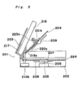
- the tape recorder main body (201) is composed of a case main body (202) and a tape cassette holder (203) pivotally mounted on the case main body (202), with an auxiliary chassis (204) being provided pivotally on the tape cassette holder (203).
- the case main body (202) is provided at its approximate center with a motor for disc use (205), a centering member (207) mounted on the rotary shaft (206) of the motor for disc use (205), and a turntable (208).
- a reel shaft driving means (215) is provided sideways of the case main body (202), composed of flywheels (210a), (210b) which are operatively cooperated with the tape motor (not shown) through the belt, with the capstans (209a), (209b) being upwardly projected, a driving gear (211) to be driven by the reel motor as shown in Fig. 8, and a transmission gear (213) to be mounted rotatably so as to be vertically moved somewhat by the spring (212) and to be interlocked with the driving gear (211).
- an accommodating portion (217) for accommodating the tape cassette (216) is formed on the tape cassette holder (208), and also, the auxiliary chassis (204) is pivotally mounted on the lower face thereof, with the magnet clamper (209) is mounted above and below for its free rotation on the auxiliary chassis (204) in opposition to the turntale (208).
- a transmission means (222) is provided which is composed of transmission gears (218a), (218b) opposite to the transmission gear (213), the intermediate gears (220a), (220b) to be mounted on the levers (219a), (219b) and to be interlocked with the transmission gears (218a), (218b), and the reel gears (221a), (221b) to be interlocked with the intermediate gears (220a), (220b), with the reels shafts (223a), (223b) being formed integrally on the reel gears (221a), (221b).
- the tape cassette holder (203) is pivoted in an upper direction as shown in Fig. 5.
- the disc (224) is placed manually on the turntable (208).
- the auxiliary chassis (204) is pivoted somewhat downwardly from the tape cassette holder (203), and the reel shafts (221a), (221b) are retreated from the tape admission passasge of the tape cassette holder (203), so that the tape cassette (216) may be inserted, accommodated without being interfered with into the tape cassette holder (203).
- the auxiliary chassis (204) is accommodated into the tape cassette holder (208), and the tape hubs (225a), (225b) are engaged into the reel shafts (221a), (221b).
- the capstans ( 209a), (209b) pass through the holes to insert into the tape cassette (216).
- the flywheels (210a), (210b) are rotated by the tape motor. But only the pinch roller (not shown) located on the right side adhere under pressure against the capstan (209a) through the tape (227) to run the tape (227) at the constant speed in the forward direction, so that the signal to be recorded on the tape (227) is reproduced by the magnetic head (not shown).
- the rotation force of the tape motor is transmitted through the driving gear (212), the transmission gear (213), the transmission gear (218a) and the intermediate gear (220a) to rotate the reel gear (221a), so that the hub is also rotated so as to wind the tape (227) ran at the constant speed by the capstan (209a) and the pinch roller.
- the pinch roller which has adhered under pressure against the capstan (209a) on the left side is separated to cause the pinch roller to adhere against the capstan (209b) on the right side through the tape (227), and also, the tape motor is rotated in a direction opposite to that provided so far, so that the tape (227) runs at the constant speed in the direction opposite to the previous direction to effect the regenerating operation in the reverse direction.
- the intermediate gear (220a) is separated from the reel gear (221a), the intermediate gear (220b) on the left side is interlocked with the reel gear (221b) so as to transmit the rotation force of the tape motor into the reel gear (221b) in the same way as described hereinabove to rotate the reel shaft (223) for winding the tape (227).
- the transmission means (222) is adapted to drive the right, left reel shafts (223a), (223b) by the intermediate gears (220a), (220b) and the transmission gears (218a), (218b) separately provided, but the rotation forces may be transmitted into the right, left reel shafts (223a), (223b) respectively through a plurality of intermediate gears in the transmission gears, with the transmission gears serving as right, left reel shafts (223a), (223b).
- the disc motor and the tape motor are separately provided, the disc motor and the tape motor may be provided in one when the disc and the tape are not required to be played simultaneously like a regenerating exclusive machine.
- the 8 cm CD disc may be placed on the turntable (224) without being interfered with by the capstans (209a), (209b), thus resulting in approximately the same size as that of the conventional head horn stereo tape recorder.
- the Philips type of compact tape cassette (216) is made thicker in the head inserting portion (228) and thinner in the hub accommodating portion (229), the thickness of the tape cassette holder (203) is hardly increased when the transmission means (222) is provided in a position facing the hub accommodating portion (229) of the compact tape cassette (216).
- the turntable for the disc musical performance use, the capstan and the reel shaft driving means are provided on the case main body, the reel shaft, and the transmission means for giving the rotating force into the reel shaft are provided on the auxiliary chassis pivotally provided on the tape cassette holder. Therefore, when the tape cassette is engaged with the tape cassette holder, the reel shaft and so on are retreated from the admission passage not to interfere with the engagement of the tape cassette or the turntable is exposed, so that the disc may be engaged with the turntable or may be disengaged from it.
- the reel shaft driving means and the transmission means are engaged with each other to rotate the reel shaft for winding the tape.
- the disc player may be built-in within the head horn type of tape recorder without increasing the size and thickness of the main body.
- a cassette holder (302) has the accommodating portion (304) of the tape cassette (303), and is supported through the shaft (305) on the case main body (301).
- the auxiliary chassis (306) is further mounted pivotally on the cassette holder (302).
- the case main body (301) is provided with a spindle motor (307), a centering portion (308) made of a magnetic material, and also, with a turntable (309) mounted on the rotary shaft (310) of the spindle motor (307).
- a clamper (331) which has a calked shaft (311), a chucking member (313) mounted rotatably on the shaft (311) with a driving gear (312) being formed, a disc restraint plate (315) which is integrally rotated with the chucking member (313), with the magnets (314), (314) being mounted in opposition to the turntable (309), a transmission gear (319) to be mounted on the mounting metal fixture (318) supported on the shaft (317) to interlock with the driving gear (312), and right, left reel shafts (320a), (320b) having reel gears (321a), (321b) to be interlocked with the transmission gear (319) through the transmission gears (322a), (322b) are provided on the auxiliary chassis (306).
- capstan motor (323), capstans (324a), (324b) are provided on the auxiliary chassis (306), with the flywheels (326a), (326b) to be operatively cooperated and rotated with the belt (325) being mounted on the capstan motor (323).
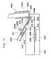
- the cassette holder (302) In order to engage the CD disc (327) to be played and the tape cassette (303), the cassette holder (302) is pivoted in an opening direction as shown in Fig. 9. In this condition, the turntable (309) is externally exposed, the opening portion of the cassette holder (302) is upwardly opened, and the auxiliary chassis (306) is downwardly positioned away from the cassette holder (302), so that the reel shafts (320a), (320b), the projecting portions of the capstans (324a), (324b) and so on are not positioned within the cassette holder (302).
- the tape cassette is engaged into the cassette holder (302) by the insertion of the tape cassette (303) from the opening of the cassette holder (302). Also, take the CD disc (327) manually above the turntable (309) to engage the centering portion (308) into the central hole of the CD disc (327), so that the CD disc (327) may be engaged onto the turntable (309).
- the spindle motor (307) is rotated and the turntable (309) is also rotated if the CD regenerating button is operated.
- the CD disc (327) is also rotated together with the turntable (309). Accordingly, the light beams illuminated from the light pick up (not shown) are reflected in accordance with the pit and land (?) recorded on the surfaces of the CD disc (327). The reflected light beams are detected by the photo cells within the light pick up and are added into the signal processing circuit, so that the recorded voice signals are drawn out to effect the performance of the music and so on.
- the driving gear (312) of the clamper (316) is rotated together with the turntable (309) and the transmission gear (319) to be interlocked with the driving gear (312) is also rotated.
- the transmission gear (319) remains neutral without the interlocking of either of the transmission gears (322a), (322b).
- the capstan motor (323) is not rotated, either, so that the tape cassette (303) is not influenced at all.
- the capstan motor (323) In order to reproduce the tape in the forward direction, operate the forward direction regenerating button, and the capstan motor (323) is rotated in the given direction, and also, the head base (not shown) is slided in the musical performance direction to depress the tape agaisnt the head and to depress the pinch roller (not shown) through the tape gainst the capstan (324a) on the left side.
- the tape is ran at the constant speed by the capstan (324a) and the pinch roller so as to reproduce the siganls recorded by the head.
- the driving gear (312) of the clamper (316) is also rotated together with the turntable (309), and the reel gear (312a) is rotated through the transmission gear (319) to be interlocked with the driving gear (312), and the transmission gear (322a) so as to rotate the reel shaft (320a).
- the reel hub (328a) to be engaged with the reel shaft (320a) is also rotated to wind the tape ran at the constant speed by the capstan (324a) and the pinch roller.
- the speed of the tape to be wound becomes faster to pull the tape. But in the present invention, as the turntable (309) and the clamper (316) are magnetically combined with each other, the slip is caused not to apply the tension upon the tape more than necessary.
- the CD dics (327) is rotated at this time, the voltage is not applied upon the regenerating circuit of the light pick up or the like, and the signals are not reproduced, thus causing no influences.
- the capstan motor (323) or the like is automatically rotated oppositely to the rotation given so far and is rotated in the opposite direction.
- the pinch roller which has adhered under pressure against the capstan (324a) is separated and the other pinch roller is instead depressed against the capstan (324).
- the transmission gear (319) is interlocked with the reel gear (321b) through the transmission gear (322b).
- the tape is ran at the constant speed by the capstan (324b) and the pinch roller in a direction opposite to that provided so far so as to effect the regeneration in the opposite direction.
- the transmission gear (319) is interlocked with the reel gear (321b) through the transmission gear (322b) and the spindle motor (323) is also rotated in the opposite direction, so that the reel shaft (320b) is also rotated reversely to wind the tape ran at the constant speed, by the reel hub (328b).
- capstan motor (323), and the flywheels (326a), (326b) and so on to be driven by the capstan motor (323) were provided on the auxiliary chassis (306), they may be provided within the case main body (301).
- the auxiliary chassis is further pivotally mounted on the cassette holder pivotally provided on the case main body, the clamper having the driving gear, the transmission gear to be interlocked with the driving gear, the reel shaft and so on are provided on the auxiluary chassis.
- the clamper and the turntable for the disc musical performance use provided on the case main body are magnetically combined, when the cassette holder is positioned in the operating condition, to transmit the rotation force of the spindle motor into the reel shaft so that the reel shaft may be rotated by the spindle motor, thus requiring no motor for driving the reel shaft so as to make the size smaller.
- the clamper is magnetically, contained with the turntable, the amount of the tape to be wound by the reel hub increases and the tension for winding the tape ran at the constant speed by the capstan and the pinch roller becomes larger, so that the clamper and the turntable are slipped to prevent the tension more than necessary from being applied on the tape to be wound.
- a cassette holder (402) has an accommodating portion (404) of the tape cassette (403). It is supported by a shaft (405) on the case main body (401). Furthermore, an auxiliary chassis (406) is pivotally mounted on the cassette holder (402).
- the case main body (401) is provided with a spindle motor 407), a centering portion (408) made of a magnetic material and also, a turntable (410) mounted on the rotary shaft (409) of the spindle motor (407).
- a clamper (413) mounted rotatably on the calked shaft (411), with magnets (412), (412) being provided with respect to the turntable (410), a capstan motor (414), flywheels (418a), (418b) interlocked with the rotary shaft (415) of the capstan motor (414) by the belt (416) and having the capstan (417a), (417b), an idler gear (419) to be rotated by the belt (416), a driving gear (420) to be interlocked with the idler gear (419), and a transmission gear (423) mounted on the mountng metal fixture (422) supported by the shaft (421) and to be selectively interlocked with the reel gears (425a), (425b) having the reel shafts (424a), (424b) are provided on the auxiliary chassis (406).
- the opening of the cassette holder (402) is directed at the top face, and also, the turntable (410) is externally exposed when the cassette holder (402) is rotated. Accordingly, the hole of the 8 cm CD disc (426) is engaged into the centering portion (408) to engage the CD disc (426) with the turntable (410). Also, at this time, the auxiliary chassis (406) is away from the cassette holder (402) and the reel shafts (424a), (424b) and the capstans (417a), (417b) are retreated from the admission passage, so that the cassette tape (403) may be engaged with the accommodating portion (404) of the cassette holder (402).
- the auxiliary chassis (406) is accommodated within the cassette holder (402), the reel shafts (424a), (424b) are engaged with the reel hubs (427a), (427b), and also, the capstans (417a), (417b) are inserted into the holes of the cassette tape (403).
- the magnets (412), (412) of the clamper (413) adhere on the turntable (410) to clamp the CD disc (426) into a stand-by condition.
- the spindle motor (407) When the regenerating button is operated to effect the musical performance of the CD disc (426), the spindle motor (407) is rotated, and the CD disc (426) is rotated together with the turntable (410), so that the signals recorded on the CD disc (426) are taken out by the light pick up (not shown) to reproduce the music and so on.
- the capstan motor (414) When, for example, the forward direction regenerating button (not shown) is operated to reproduce the cassette tape (403), the capstan motor (414) is, rotated to rotate the flywheels (418a), (418b) through the belt (416) by the rotating force of the capstan motor (414). When the flywheels (418a), (418b) are rotated, the capstans (417a), (417b) are also rotated. As the pinch roller (not shown) adheres under pressure through the tape against the capstan 417a) on the left side, the tape is ran at the constant speed from the right to the left to reproduce by the magnetic head (not shown) the signals recorded on the tape.
- the idler gear (419) is also rotated by the rotating force of the capstan motor (415) to be transmitted through the belt (416), the rotating force of the idler gear (419) rotates the driving gear (420), the reel gear (425a) through the transmission gear (423) to be interlocked with the reel gear (425a) at this time. Accordingly, the reel hub (427a) to be engaged with the reel shaft (424a) of the reel gear (425a) is rotated to wind the tape ran at the constant speed by the capstan (417a) and the pinch roller.
- the regenerating button of the CD player is operated to renegerate the signal recorded on the CD disc (426).
- the recording button of the tape is operated, the tape is ran at the constant speed in the right direction by the capstan (417b) and the pinch roller as described hereinabovee, and the tape ran at the constant speed is wound by the reel hub (427b), and also, the electric circuit is watched into the recording condition. Accordingly, the signals generated by the CD disc (426) are fed onto the magnetic head and are recorded on the tape.
- the rotation force of the reel gears (425a), (425b) are obtained from the capstan motor (414). But when the tape is not required to be recorded, the rotation force of the reel gears (425a), (425b) may be obtained by the spindle motor (419).
- the turntable for the disc musical performance use is provided at the center of the case main body, the driving portion necessary for driving the tape for the reel shaft, the capstan and so on is mounted on the auxiliary chassis pivotally mounted on the cassette holder to enable the 8 cm CD disc to be reproduced with a size which is approximately the same as the conventional head horn type of tape recorder.
- the disc may be replaced with the cassette tape being engaged into the cassette holder by the pivoting of the cassette holder into the cassette taking-out position as the turntable is externally exposed.
- the tape driving mechanism of the capstan or the reel shaft and so on is provided on the auxiliary chassis to be pivoted together with the cassette holder, the disc may be easily replaced, because the turntable is not interfered with by the tape driving mechanism.
- the tape driving mechanism such as the reel shaft, the capstan or the like is retreated from within the cassette holder, so that the cassette tape may be engaged into the cassette holder.
Landscapes
- Holding Or Fastening Of Disk On Rotational Shaft (AREA)
- Indexing, Searching, Synchronizing, And The Amount Of Synchronization Travel Of Record Carriers (AREA)
- Feeding And Guiding Record Carriers (AREA)
Applications Claiming Priority (8)
| Application Number | Priority Date | Filing Date | Title |
|---|---|---|---|
| JP268988/88 | 1988-10-25 | ||
| JP26898888A JPH02116071A (ja) | 1988-10-25 | 1988-10-25 | ディスクプレーヤ付テープレコーダ |
| JP54503/89 | 1989-03-06 | ||
| JP5450389A JPH02232882A (ja) | 1989-03-06 | 1989-03-06 | ディスクプレーヤ付テープレコーダ |
| JP8655089A JPH02265081A (ja) | 1989-04-05 | 1989-04-05 | ディスクプレーヤー付テープレコーダ |
| JP86550/89 | 1989-04-05 | ||
| JP10077289A JPH02278587A (ja) | 1989-04-20 | 1989-04-20 | ディスクプレーヤ付テープレコーダ |
| JP100772/89 | 1989-04-20 |
Publications (2)
| Publication Number | Publication Date |
|---|---|
| EP0366118A2 true EP0366118A2 (de) | 1990-05-02 |
| EP0366118A3 EP0366118A3 (de) | 1991-07-03 |
Family
ID=27463072
Family Applications (1)
| Application Number | Title | Priority Date | Filing Date |
|---|---|---|---|
| EP19890119845 Withdrawn EP0366118A3 (de) | 1988-10-25 | 1989-10-25 | Bandrekorder mit Plattenspieler |
Country Status (4)
| Country | Link |
|---|---|
| US (1) | US5054015A (de) |
| EP (1) | EP0366118A3 (de) |
| KR (1) | KR900006931A (de) |
| CA (1) | CA2001525A1 (de) |
Cited By (6)
| Publication number | Priority date | Publication date | Assignee | Title |
|---|---|---|---|---|
| EP0526215A3 (en) * | 1991-08-02 | 1994-08-10 | Sony Corp | Loading apparatus for a tape cassette and a disk |
| US5488522A (en) * | 1994-11-14 | 1996-01-30 | Combyte, Inc. | Ejection apparatus for ejecting storage media positioned in a computer mass storage media drive |
| GB2342763A (en) * | 1998-10-16 | 2000-04-19 | Alco Electronics Ltd | Combined CD and tape cassette playing apparatus |
| US6064640A (en) * | 1995-12-15 | 2000-05-16 | Fujitsu Limited | Optical disk apparatus and medium carrier and medium turntable for optical disk apparatus |
| US6069858A (en) * | 1995-12-15 | 2000-05-30 | Fujitsu Limited | Optical disk apparatus |
| US6292452B1 (en) | 1995-12-15 | 2001-09-18 | Fujitsu Limited | Optical disk apparatus for using multiple types of disks |
Families Citing this family (8)
| Publication number | Priority date | Publication date | Assignee | Title |
|---|---|---|---|---|
| JPH0512793A (ja) * | 1991-07-04 | 1993-01-22 | Matsushita Electric Ind Co Ltd | 軸受装置 |
| DE4228367C2 (de) * | 1991-09-18 | 2001-02-08 | Samsung Electronics Co Ltd | Kassettenladevorrichtung für Kassettenspieler |
| JP3381277B2 (ja) * | 1992-06-23 | 2003-02-24 | ソニー株式会社 | ディスクプレーヤ装置 |
| JP2974868B2 (ja) * | 1993-03-19 | 1999-11-10 | シャープ株式会社 | ディスク駆動装置およびディスク装置 |
| US6044058A (en) * | 1993-08-24 | 2000-03-28 | Matsushita Electric Industrial Co., Ltd. | Adaptor cartridge for mounting a second disk in a device designed to mount a first-disk cartridge |
| DE29910212U1 (de) | 1999-06-11 | 1999-09-16 | Sandhoo, Sarbjeet Singh, 67133 Maxdorf | Tragbares Audiokombinationsgerät |
| US8028311B2 (en) * | 2004-10-18 | 2011-09-27 | Gilovich Paul A | Multiple positioner data storage device |
| US20120166547A1 (en) * | 2010-12-23 | 2012-06-28 | Sharp Michael A | Systems and methods for recording and distributing media |
Family Cites Families (13)
| Publication number | Priority date | Publication date | Assignee | Title |
|---|---|---|---|---|
| US2694110A (en) * | 1947-06-27 | 1954-11-09 | Int Electronics Co | Equipment for use with magnetic tape records |
| FR1035756A (fr) * | 1951-03-10 | 1953-08-31 | Appareil d'enregistrement et de reproduction électromagnétique, notamment de sons adaptable à un tourne-disques | |
| FR1178828A (fr) * | 1957-07-12 | 1959-05-15 | Dispositif pour transformer un tourne-disque ou appareil analogue en un appareil de reproduction sonore à bande ou fil magnétique | |
| US3624310A (en) * | 1969-11-21 | 1971-11-30 | Motorola Inc | Tape player phonograph adapter permitting operation of tape cartridges or cassettes on conventional phonograph |
| FR2161529A5 (de) * | 1971-11-24 | 1973-07-06 | Gilbraut Clement | |
| AT364546B (de) * | 1979-08-07 | 1981-10-27 | Philips Nv | Aufzeichnungs- und/oder wiedergabegeraet |
| US4331988A (en) * | 1980-05-08 | 1982-05-25 | Funai Electric Co., Ltd. | Cassette base for a video tape recorder |
| JPS58218074A (ja) * | 1982-06-10 | 1983-12-19 | Canon Inc | 情報処理装置 |
| JPS59107449A (ja) * | 1982-12-10 | 1984-06-21 | Sanyo Electric Co Ltd | デイスク駆動装置 |
| JPS6277497U (de) * | 1985-10-30 | 1987-05-18 | ||
| JPS6290447U (de) * | 1985-11-20 | 1987-06-10 | ||
| AU601385B2 (en) * | 1985-12-28 | 1990-09-13 | Hewlett-Packard Company | Disk-drive-compatible magnetic tape cartridge with tape-positioning guide for accurately positioning magnetic tape with respect to disk drive head |
| AT384688B (de) * | 1986-03-07 | 1987-12-28 | Philips Nv | Aufzeichnungs- und/oder wiedergabegeraet mit einem zum aufnehmen eines aufzeichnungstraegers vorgesehenen aufnahmeraum |
-
1989
- 1989-10-24 US US07/427,204 patent/US5054015A/en not_active Expired - Fee Related
- 1989-10-24 KR KR1019890015270A patent/KR900006931A/ko not_active Withdrawn
- 1989-10-25 CA CA002001525A patent/CA2001525A1/en not_active Abandoned
- 1989-10-25 EP EP19890119845 patent/EP0366118A3/de not_active Withdrawn
Cited By (8)
| Publication number | Priority date | Publication date | Assignee | Title |
|---|---|---|---|---|
| EP0526215A3 (en) * | 1991-08-02 | 1994-08-10 | Sony Corp | Loading apparatus for a tape cassette and a disk |
| US5488522A (en) * | 1994-11-14 | 1996-01-30 | Combyte, Inc. | Ejection apparatus for ejecting storage media positioned in a computer mass storage media drive |
| US6064640A (en) * | 1995-12-15 | 2000-05-16 | Fujitsu Limited | Optical disk apparatus and medium carrier and medium turntable for optical disk apparatus |
| US6069858A (en) * | 1995-12-15 | 2000-05-30 | Fujitsu Limited | Optical disk apparatus |
| US6292452B1 (en) | 1995-12-15 | 2001-09-18 | Fujitsu Limited | Optical disk apparatus for using multiple types of disks |
| GB2342763A (en) * | 1998-10-16 | 2000-04-19 | Alco Electronics Ltd | Combined CD and tape cassette playing apparatus |
| GB2342763B (en) * | 1998-10-16 | 2001-08-29 | Alco Electronics Ltd | Combined CD/cassette playing mechanism |
| US6373804B2 (en) | 1998-10-16 | 2002-04-16 | Alco Electronics Limited | CD/cassette playing mechanism |
Also Published As
| Publication number | Publication date |
|---|---|
| EP0366118A3 (de) | 1991-07-03 |
| KR900006931A (ko) | 1990-05-09 |
| CA2001525A1 (en) | 1990-04-25 |
| US5054015A (en) | 1991-10-01 |
Similar Documents
| Publication | Publication Date | Title |
|---|---|---|
| EP0366118A2 (de) | Bandrekorder mit Plattenspieler | |
| CA1289662C (en) | Cassette adapter for playback device, such as a compact disk player | |
| US4050087A (en) | Cassette tape recording and/or reproducing apparatus | |
| KR880001972B1 (ko) | 기록 재생 장치 | |
| JPS6044740B2 (ja) | テ−プカセツト | |
| EP0228904B1 (de) | Magnetbandkassetten | |
| US4712145A (en) | Operating mechanism for small portable cassette tape player | |
| CN1029437C (zh) | 盒式磁带信号记录重放系统 | |
| EP0768667B1 (de) | Magnetisches Aufzeichnungs- und Wiedergabegerät und Videokamera damit | |
| JPS583160A (ja) | 小型テ−プカセツト用アダプタ | |
| US4021854A (en) | Miniature cassette tape recorder | |
| JPH02116071A (ja) | ディスクプレーヤ付テープレコーダ | |
| JPH08235685A (ja) | テープ駆動装置 | |
| US4396169A (en) | Magnetic tape cassette | |
| JPS6037736Y2 (ja) | テ−プカセツト | |
| JPS6112626Y2 (de) | ||
| EP1622139A2 (de) | Spulen-Scheibenbremsvorrichtung | |
| GB2136397A (en) | Magnetic tape cassette containing two tapes | |
| JPH08102115A (ja) | ディスク装置 | |
| JPS62184653A (ja) | テ−プレコ−ダ− | |
| JPS58125263A (ja) | アダプタと結合できる情報の記録又は再生装置 | |
| JPS6145751U (ja) | カセツト式記録再生装置 | |
| JPS61229252A (ja) | テ−プレコ−ダ | |
| JPH05128671A (ja) | テープレコーダ | |
| JPH05101500A (ja) | テープレコーダ |
Legal Events
| Date | Code | Title | Description |
|---|---|---|---|
| PUAI | Public reference made under article 153(3) epc to a published international application that has entered the european phase |
Free format text: ORIGINAL CODE: 0009012 |
|
| 17P | Request for examination filed |
Effective date: 19891025 |
|
| AK | Designated contracting states |
Kind code of ref document: A2 Designated state(s): DE ES FR GB IT |
|
| PUAL | Search report despatched |
Free format text: ORIGINAL CODE: 0009013 |
|
| AK | Designated contracting states |
Kind code of ref document: A3 Designated state(s): DE ES FR GB IT |
|
| STAA | Information on the status of an ep patent application or granted ep patent |
Free format text: STATUS: THE APPLICATION HAS BEEN WITHDRAWN |
|
| 18W | Application withdrawn |
Withdrawal date: 19920921 |