EP0365703A1 - Handgeführte Maschine - Google Patents
Handgeführte Maschine Download PDFInfo
- Publication number
- EP0365703A1 EP0365703A1 EP88117867A EP88117867A EP0365703A1 EP 0365703 A1 EP0365703 A1 EP 0365703A1 EP 88117867 A EP88117867 A EP 88117867A EP 88117867 A EP88117867 A EP 88117867A EP 0365703 A1 EP0365703 A1 EP 0365703A1
- Authority
- EP
- European Patent Office
- Prior art keywords
- drive shaft
- pipe
- shaft
- driving mechanism
- hand
- Prior art date
- Legal status (The legal status is an assumption and is not a legal conclusion. Google has not performed a legal analysis and makes no representation as to the accuracy of the status listed.)
- Granted
Links
Images


Classifications
-
- A—HUMAN NECESSITIES
- A01—AGRICULTURE; FORESTRY; ANIMAL HUSBANDRY; HUNTING; TRAPPING; FISHING
- A01D—HARVESTING; MOWING
- A01D34/00—Mowers; Mowing apparatus of harvesters
- A01D34/835—Mowers; Mowing apparatus of harvesters specially adapted for particular purposes
- A01D34/90—Mowers; Mowing apparatus of harvesters specially adapted for particular purposes for carrying by the operator
Definitions
- This invention relates to an improvement in hand-held machines such as mowers or cutting or trimming devices or cleavers which are driven by a small engine.
- Such a hand-held machine comprises an operational means like a cutter blade which is rotatably provided at an end of a drive shaft pipe which connects the operational means with a driving mechanism such as an engine to rotate the means at high speed.
- the length of the drive shaft pipe of the aforementioned hand-held machines is generally determined to allow the users to work in a comfortable posture, the length between the driving mechanism and means tends to become long. They inconveniently require extensive space during transportation and storage, and present problems in working efficiency depending on the location or topography of the land.
- a hand-held machine wherein a drive shaft pipe which is telescopically constructed internally houses a shaft of the driving mechanism side with a joint of a special shape and another shaft of the operational means side which can receive the joint of the special shape.
- the proposed machine is not completely free of problems as it has inferior sectional strength on the drive shaft, and rotational force cannot be transmitted smoothly due to the play on the joint.
- this invention aims to provide a hand-held machine having an operational means which is attached rotatably at an end of a drive shaft pipe, and which is connected to a driving mechanism via a drive shaft for rotation.
- the drive shaft pipe comprises a drive shaft pipe of smaller diameter on the side of the operational means and another drive shaft pipe of slightly larger diameter on the side of the driving mechanism to which said smaller diameter pipe is inserted while the drive shaft comprises a shaft of circular section on the side of the driving mechanism and another shaft pipe on the side of operational means to which said circular section shaft is inserted.
- At least one one-way clutch is provided at an end of the shaft pipe on the side of the operational means to be engaged with said circular section shaft.
- a fixing means is attached on the larger diameter drive shaft pipe for fixedly retaining the smaller diameter drive shaft pipe in the axial direction thereof so as to prevent the sectional strength from deteriorating as well as to enhance smooth transmission of revolutional force.
- the rotational force of a driving mechanism such as an engine is transmitted to the operational means via a drive shaft with a circular section, a one-way clutch and a drive shaft pipe on the side of the operational means.
- a bearing member is provided inside the drive shaft pipe in a manner to be flexibly retained in order to axially support the shaft so that the displacement of the shaft may be prevented even at the time of rotation.
- the drive shaft with the circular section on the side of the driving mechanism may have a smaller diameter at a portion thereof. If the diameter is designed too small to be connected to the other shaft with the one-way clutch, the transmission of the rotational force may be suspended if necessary. Moreover, if a switching means is mounted on the fixing means, and is operated by a switch provided on the smaller diameter drive shaft pipe in the longitudinal direction, risks which otherwise may be produced when a user grips the shaft at a position too close to the operational means could be avoided in advance.
- the machine comprises a nylon cord cutter 12 which is rotatably mounted on an end of a drive shaft pipe 10 as a means of cutting or trimming.
- the machine cuts and cleaves weeds and grass by the cutter 12 which is driven to rotate at high speed by the output from an engine 14 which is transmitted via a drive shaft 16.
- the machine may also be used for cutting branches growing in the lower part of a tree.
- the drive shaft pipe 10 comprises a drive shaft pipe 10a having a smaller diameter on the side of the nylon cord cutter 12, and another drive shaft pipe 10b on the side of the engine having a slightly larger diameter so as to receive the first pipe 10a and move axially in a telescopic mode.
- the drive shaft 16 comprises a first shaft 16a on the side of the engine 14 having a circular section, a second pipe shaft 16b which sheathes the shaft 16a on the side of the means, and a one-way clutch 18 provided at one end of the shaft 16b which is actuated by normal rotation of the shaft 16a.
- a solid shaft is used as the shaft 16a of the circular section in this embodiment, a pipe may be used for minimizing the weight of the device.
- One end of the drive shaft pipe 10b is attached with a sleeve-like cover member 20 and a fixing means 22 is provided on the cover member 20.
- a fixing means 22 is provided on the cover member 20.
- the drive shaft pipe 10a may be retained fixedly at a predetermined axial position.
- Suitable stop means should be provided at respective ends of drive shaft pipes 10a and 10b.
- a bearing member 24 of the shaft 16a is provided movably in the drive shaft pipe 10b, and is attached with a coil spring 26 to the main body of driving mechanism including the engine 14 via the drive shaft pipe 10b (refer to Fig. 2).
- the machine thus structured is operated in practice as follows: the drive shaft pipe 10a and the shaft 16a of circular section are slided along the drive shaft pipe 10b and the shaft 16b for a suitable distance by manipulating the fixing means 22 to have a desired length, and the length of the drive shaft pipe 10 is fixed with the fixing means 22.
- the rotational force of the engine 14 is transmitted constantly as it is to the nylon cord cutter 12 via the shaft 16a, one-way clutch 18 and the shaft 16b.
- As the rotational force is constantly transmitted to nylon cord cutter 12 intact, there will be no chattering or deterioration in sectional strength.
- lengths of the drive shaft pipe 10 and the drive shaft 16 may be determined arbitrarily simply by manipulating the fixing means 22.
- the shaft 16a Due to the effect of the coil spring 26 used for flexibly retaining the bearing 24 in the axial direction, the shaft 16a is conveniently supported axially so that no displacement of the shaft 16 would be produced at the time of rotation.
- Fig. 3 shows another mower or cutter or trimmer embodying this invention hand-held machine wherein a steel cutter blade 28 receiving substantially no load at the time of rotation is used as a cleaving means in place of the nylon cord cutter on which load is constantly applied. Further, a one-way clutch 18a which is actuated with the normal rotation of the shaft 16a and another one-way clutch 18b which is actuated with the reverse rotation of the shaft 16a are provided adjacent to each other at the end of the shaft on the side of the means 16b, and the shaft 16a is reduced in diameter at a predetermined position.
- This embodiment not only achieves an effect similar to the first embodiment but also conveniently prevents vibration or noises with the effect of the pair of one-way clutches which may otherwise be caused by the inertia of the steel cutter blade 28 when the revolution rate of the engine is once reduced and then increased. Even if the length of the shaft is adjusted erroneously too short, the transmission of the rotational power is broken instantaneously at the point 30 when the shaft 16a is aligned with the one-way clutch 18a where the diameter is narrowed to thereby further secure the safety of the users.
- the bearing of the one-way clutch 18b is made of such elastic materials as rubber, the impact felt on the device when the steel cutter contacts a stone or the like will not cause a bite by the one-way clutch into the shaft. This also contributes to reduction of manufacture cost.
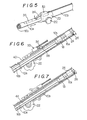
- Figs. 4 and 5 show another mower or cutter or trimmer embodying the hand-held machine according to this invention wherein an engine switch 32 is provided on the fixing means 22, and a lever 34 for the switch 32 is attached in a manner to extend over a flat handle section 36 on the surface of the shaft 10a longitudinally.
- this embodiment can avoid various types of dangers which might otherwise be inflicted on the users. For instance, if the length of the engine shaft is excessively shortened, or the shaft is twisted from the housing means peripherally to disengage the lever 34 from the section 36, the engine 14 will be suspended instantly. Similar effect can be attained even if the lever 34 of the switch 32 is structured to extend over a slit 40 opened on the peripheral surface of the drive shaft pipe 10a via a hole 38 (refer to Fig. 6) or the switch is replaced by a magnetic switch 42 having a magnet 44 as an operational means thereof positioned inside of the pipe 10a (refer to Fig. 7).
- this invention hand-held machine can adjust the length thereof arbitrarily, it can enhance workability as well as minimize the space necessary for transportation or storage.
- the rotational force of the driving mechanism can securely be transmitted to the operational means via the shaft, one-way clutch and operational side shaft, the problems encountered in the prior art such as the reduction of sectional area can be avoided to further secure effective operation. It can effectively prevent vibration or noises and can secure the safety of users.
Priority Applications (4)
| Application Number | Priority Date | Filing Date | Title |
|---|---|---|---|
| AU24193/88A AU614548B2 (en) | 1988-10-26 | 1988-10-24 | Hand-held machine |
| DE8888117867T DE3875249T2 (de) | 1988-10-26 | 1988-10-26 | Handgefuehrte maschine. |
| EP88117867A EP0365703B1 (de) | 1988-10-26 | 1988-10-26 | Handgeführte Maschine |
| US07/265,250 US4899446A (en) | 1988-10-26 | 1988-10-31 | Hand-held machine with power disengaging means |
Applications Claiming Priority (1)
| Application Number | Priority Date | Filing Date | Title |
|---|---|---|---|
| EP88117867A EP0365703B1 (de) | 1988-10-26 | 1988-10-26 | Handgeführte Maschine |
Publications (2)
| Publication Number | Publication Date |
|---|---|
| EP0365703A1 true EP0365703A1 (de) | 1990-05-02 |
| EP0365703B1 EP0365703B1 (de) | 1992-10-07 |
Family
ID=8199492
Family Applications (1)
| Application Number | Title | Priority Date | Filing Date |
|---|---|---|---|
| EP88117867A Expired - Lifetime EP0365703B1 (de) | 1988-10-26 | 1988-10-26 | Handgeführte Maschine |
Country Status (4)
| Country | Link |
|---|---|
| US (1) | US4899446A (de) |
| EP (1) | EP0365703B1 (de) |
| AU (1) | AU614548B2 (de) |
| DE (1) | DE3875249T2 (de) |
Cited By (9)
| Publication number | Priority date | Publication date | Assignee | Title |
|---|---|---|---|---|
| EP0653364A2 (de) * | 1993-11-09 | 1995-05-17 | Black & Decker Inc. | Verbesserte Stielzusammensetzung |
| GB2320665A (en) * | 1996-12-24 | 1998-07-01 | Stihl Maschf Andreas | Cutting tool with a divisible guide tube |
| FR2792239A1 (fr) * | 1999-04-16 | 2000-10-20 | Stihl Maschf Andreas | Outillage entraine par moteur |
| US6880248B2 (en) | 1999-04-16 | 2005-04-19 | Andreas Stihl Ag & Co. | Motor driven implement |
| EP1661447A1 (de) * | 2004-11-25 | 2006-05-31 | MOGATEC Moderne Gartentechnik GmbH | Rasentrimmer |
| CN100415074C (zh) * | 2001-02-27 | 2008-09-03 | 本田技研工业株式会社 | 一种植物铲除装置 |
| JP2013198940A (ja) * | 2012-03-23 | 2013-10-03 | Makita Corp | 動力工具 |
| EP3135092A1 (de) * | 2015-08-27 | 2017-03-01 | AC (Macao Commerical Offshore) Limited | Verbessertes elektrowerkzeug und ein drehungsübertragungsmechanismus für ein elektrowerkzeug |
| CN106475972A (zh) * | 2015-08-27 | 2017-03-08 | Ac(澳门离岸商业服务)有限公司 | 动力工具、旋转传输机构及控制线式修剪机后颤的方法 |
Families Citing this family (21)
| Publication number | Priority date | Publication date | Assignee | Title |
|---|---|---|---|---|
| US5802724A (en) * | 1994-09-09 | 1998-09-08 | Ryobi North America | Coupling for split-boom power tool |
| US5815928A (en) * | 1995-07-28 | 1998-10-06 | Wci Outdoor Products, Inc. | Portable powered lawn and garden tool |
| DE19618024A1 (de) * | 1996-05-04 | 1997-11-06 | Stihl Maschf Andreas | Arbeitsgerät zum Entasten von Bäumen |
| US5933965A (en) * | 1997-07-12 | 1999-08-10 | Fiskars Inc. | Extendable tool |
| US5933966A (en) * | 1997-07-23 | 1999-08-10 | Mcculloch Corporation | Shaft telescoping and rotational adjustment mechanism for a lawn and garden tool |
| US6006434A (en) * | 1997-09-30 | 1999-12-28 | Hoffco, Inc. | Quick-release component connector for lawn tool |
| DE10050696B4 (de) * | 2000-10-13 | 2014-12-24 | Andreas Stihl Ag & Co. | Handgeführtes Arbeitsgerät, insbesondere Hochentaster |
| US6474747B2 (en) * | 2000-11-30 | 2002-11-05 | Homelite Technologies Limited | Split boom coupling structure |
| US7913403B1 (en) * | 2006-06-08 | 2011-03-29 | Peter Douglas Willetts | Reciprocating pruning saw |
| DE202008011648U1 (de) * | 2008-09-02 | 2010-03-11 | Dolmar Gmbh | Kupplungselement |
| US9888627B2 (en) | 2012-10-15 | 2018-02-13 | Chervon (Hk) Limited | Lawncare apparatus with a foldable operating arm |
| US11606900B2 (en) | 2012-10-15 | 2023-03-21 | Chervon (Hk) Limited | Gardening tool |
| US9179597B1 (en) * | 2013-04-04 | 2015-11-10 | Adrienne B. Kaspar | Lawnmower with telescoping handle |
| DE102015207151A1 (de) * | 2015-04-20 | 2016-10-20 | Robert Bosch Gmbh | Befestigungsmittel für Handwerkzeugmaschine |
| US9844177B1 (en) | 2015-10-02 | 2017-12-19 | Adrienne B. Kaspar | Lawnmower |
| JP6799379B2 (ja) * | 2016-03-23 | 2020-12-16 | 株式会社マキタ | 作業機 |
| US20180103584A1 (en) * | 2016-10-14 | 2018-04-19 | Mark Orton | Adjustable one handed string trimmer |
| US11518018B2 (en) | 2019-01-21 | 2022-12-06 | Milwaukee Electric Tool Corporation | Power tool with non-conductive driveshaft |
| US11384719B2 (en) | 2019-03-15 | 2022-07-12 | Milwaukee Electric Tool Corporation | Fluid tank for a power tool |
| US11618149B2 (en) | 2019-04-26 | 2023-04-04 | Milwaukee Electric Tool Corporation | Telescoping tool with collapsible bearing assembly |
| US11638397B2 (en) * | 2020-02-10 | 2023-05-02 | Techtronic Cordless Gp | Control assembly coupled to handle of an implement |
Citations (3)
| Publication number | Priority date | Publication date | Assignee | Title |
|---|---|---|---|---|
| DE3213185A1 (de) * | 1982-04-08 | 1983-10-20 | ALTEK Gesellschaft für allgemeine Landtechnik mbH, 7407 Rottenburg-Hailfingen | Saege zum beschneiden von baeumen o. dgl. |
| US4411070A (en) * | 1980-03-21 | 1983-10-25 | Jarraff Industries, Inc. | Tree-trimming apparatus |
| US4654971A (en) * | 1985-09-13 | 1987-04-07 | Hudd Enterprises | Prunner with collapsible drive shaft and housing |
Family Cites Families (4)
| Publication number | Priority date | Publication date | Assignee | Title |
|---|---|---|---|---|
| US4122601A (en) * | 1976-02-06 | 1978-10-31 | Kaaz Machinery Co., Ltd. | Portable separable grass and bush cutter |
| CA1093843A (en) * | 1976-12-03 | 1981-01-20 | George C. Ballas, Sr. | Rotary cutting assembly |
| US4505040A (en) * | 1982-08-31 | 1985-03-19 | Everts Robert G | Coupling for interconnecting two handle portions of a power driven implement |
| US4463498A (en) * | 1982-08-31 | 1984-08-07 | Everts Robert G | Coupling for flailing line trimmer handles |
-
1988
- 1988-10-24 AU AU24193/88A patent/AU614548B2/en not_active Ceased
- 1988-10-26 DE DE8888117867T patent/DE3875249T2/de not_active Expired - Fee Related
- 1988-10-26 EP EP88117867A patent/EP0365703B1/de not_active Expired - Lifetime
- 1988-10-31 US US07/265,250 patent/US4899446A/en not_active Expired - Lifetime
Patent Citations (3)
| Publication number | Priority date | Publication date | Assignee | Title |
|---|---|---|---|---|
| US4411070A (en) * | 1980-03-21 | 1983-10-25 | Jarraff Industries, Inc. | Tree-trimming apparatus |
| DE3213185A1 (de) * | 1982-04-08 | 1983-10-20 | ALTEK Gesellschaft für allgemeine Landtechnik mbH, 7407 Rottenburg-Hailfingen | Saege zum beschneiden von baeumen o. dgl. |
| US4654971A (en) * | 1985-09-13 | 1987-04-07 | Hudd Enterprises | Prunner with collapsible drive shaft and housing |
Cited By (12)
| Publication number | Priority date | Publication date | Assignee | Title |
|---|---|---|---|---|
| EP0653364A2 (de) * | 1993-11-09 | 1995-05-17 | Black & Decker Inc. | Verbesserte Stielzusammensetzung |
| EP0653364A3 (de) * | 1993-11-09 | 1996-02-28 | Black & Decker Inc | Verbesserte Stielzusammensetzung. |
| US5662428A (en) * | 1993-11-09 | 1997-09-02 | Black & Decker Inc. | Shaft assembly |
| GB2320665A (en) * | 1996-12-24 | 1998-07-01 | Stihl Maschf Andreas | Cutting tool with a divisible guide tube |
| FR2792239A1 (fr) * | 1999-04-16 | 2000-10-20 | Stihl Maschf Andreas | Outillage entraine par moteur |
| US6880248B2 (en) | 1999-04-16 | 2005-04-19 | Andreas Stihl Ag & Co. | Motor driven implement |
| CN100415074C (zh) * | 2001-02-27 | 2008-09-03 | 本田技研工业株式会社 | 一种植物铲除装置 |
| EP1661447A1 (de) * | 2004-11-25 | 2006-05-31 | MOGATEC Moderne Gartentechnik GmbH | Rasentrimmer |
| JP2013198940A (ja) * | 2012-03-23 | 2013-10-03 | Makita Corp | 動力工具 |
| US9314916B2 (en) | 2012-03-23 | 2016-04-19 | Makita Corporation | Power tool |
| EP3135092A1 (de) * | 2015-08-27 | 2017-03-01 | AC (Macao Commerical Offshore) Limited | Verbessertes elektrowerkzeug und ein drehungsübertragungsmechanismus für ein elektrowerkzeug |
| CN106475972A (zh) * | 2015-08-27 | 2017-03-08 | Ac(澳门离岸商业服务)有限公司 | 动力工具、旋转传输机构及控制线式修剪机后颤的方法 |
Also Published As
| Publication number | Publication date |
|---|---|
| DE3875249D1 (de) | 1992-11-12 |
| EP0365703B1 (de) | 1992-10-07 |
| AU614548B2 (en) | 1991-09-05 |
| US4899446A (en) | 1990-02-13 |
| DE3875249T2 (de) | 1993-03-11 |
| AU2419388A (en) | 1990-04-26 |
Similar Documents
| Publication | Publication Date | Title |
|---|---|---|
| EP0365703A1 (de) | Handgeführte Maschine | |
| US4987732A (en) | Mowing apparatus having oppositely reciprocating cutters | |
| US4651420A (en) | Universal vegetation cutter or UVC | |
| JPH0783655B2 (ja) | 携帯用作業機 | |
| JP2006314278A (ja) | 刈払機 | |
| US7174639B2 (en) | Bush cutting machine | |
| US5815928A (en) | Portable powered lawn and garden tool | |
| EP0337428B1 (de) | Schneidemesser für ein Mähgerät | |
| KR100849650B1 (ko) | 예초기 | |
| EP1530890B1 (de) | Tragbares Gerät mit gedämftem Handgriff für den Gebrauch im Garten und in der Landwirtschaft | |
| CA1299996C (en) | Hand-held machine | |
| JPH0624163Y2 (ja) | ヘッジトリマー | |
| JP2009072149A (ja) | 園芸工具 | |
| JP3249489B2 (ja) | 刈取機 | |
| KR102547624B1 (ko) | 다목적 양손 예초기 | |
| EP4296538A1 (de) | Mehrgängiges automatikgetriebe für ein elektrowerkzeug | |
| CN113455172B (zh) | 生态农林用高效除草装置 | |
| EP1234491B1 (de) | Gerät zum Schneiden von Pflanzen | |
| EP1106044B1 (de) | Handtraggerät für Garten oder Landwirtschaft mit verbessertem Griff | |
| JPH077330U (ja) | 刈払機用安全カバー | |
| EP1234492A1 (de) | Gerät zum Schneiden von Pflanzen | |
| KR200335470Y1 (ko) | 예초기용 안전장치 | |
| JPS6124038Y2 (de) | ||
| JPH09233929A (ja) | 動力刈払機 | |
| NZ555255A (en) | Universal cutting device for portable trimmers |
Legal Events
| Date | Code | Title | Description |
|---|---|---|---|
| PUAI | Public reference made under article 153(3) epc to a published international application that has entered the european phase |
Free format text: ORIGINAL CODE: 0009012 |
|
| AK | Designated contracting states |
Kind code of ref document: A1 Designated state(s): DE FR GB IT |
|
| 17P | Request for examination filed |
Effective date: 19900727 |
|
| 17Q | First examination report despatched |
Effective date: 19910521 |
|
| GRAA | (expected) grant |
Free format text: ORIGINAL CODE: 0009210 |
|
| AK | Designated contracting states |
Kind code of ref document: B1 Designated state(s): DE FR GB IT |
|
| RTI2 | Title (correction) |
Free format text: HAND-HELD MACHINE. |
|
| REF | Corresponds to: |
Ref document number: 3875249 Country of ref document: DE Date of ref document: 19921112 |
|
| ET | Fr: translation filed | ||
| ITF | It: translation for a ep patent filed |
Owner name: SAIC BREVETTI S.R.L. |
|
| PLBE | No opposition filed within time limit |
Free format text: ORIGINAL CODE: 0009261 |
|
| STAA | Information on the status of an ep patent application or granted ep patent |
Free format text: STATUS: NO OPPOSITION FILED WITHIN TIME LIMIT |
|
| 26N | No opposition filed | ||
| PGFP | Annual fee paid to national office [announced via postgrant information from national office to epo] |
Ref country code: GB Payment date: 19970926 Year of fee payment: 10 |
|
| PGFP | Annual fee paid to national office [announced via postgrant information from national office to epo] |
Ref country code: FR Payment date: 19971016 Year of fee payment: 10 |
|
| PGFP | Annual fee paid to national office [announced via postgrant information from national office to epo] |
Ref country code: DE Payment date: 19971030 Year of fee payment: 10 |
|
| PG25 | Lapsed in a contracting state [announced via postgrant information from national office to epo] |
Ref country code: GB Free format text: LAPSE BECAUSE OF NON-PAYMENT OF DUE FEES Effective date: 19981026 |
|
| GBPC | Gb: european patent ceased through non-payment of renewal fee |
Effective date: 19981026 |
|
| PG25 | Lapsed in a contracting state [announced via postgrant information from national office to epo] |
Ref country code: FR Free format text: LAPSE BECAUSE OF NON-PAYMENT OF DUE FEES Effective date: 19990630 |
|
| REG | Reference to a national code |
Ref country code: FR Ref legal event code: ST |
|
| PG25 | Lapsed in a contracting state [announced via postgrant information from national office to epo] |
Ref country code: DE Free format text: LAPSE BECAUSE OF NON-PAYMENT OF DUE FEES Effective date: 19990803 |
|
| PG25 | Lapsed in a contracting state [announced via postgrant information from national office to epo] |
Ref country code: IT Free format text: LAPSE BECAUSE OF NON-PAYMENT OF DUE FEES;WARNING: LAPSES OF ITALIAN PATENTS WITH EFFECTIVE DATE BEFORE 2007 MAY HAVE OCCURRED AT ANY TIME BEFORE 2007. THE CORRECT EFFECTIVE DATE MAY BE DIFFERENT FROM THE ONE RECORDED. Effective date: 20051026 |