EP0363906B1 - Beschickungseinrichtung für Schachtöfen, insbesondere Hochöfen - Google Patents
Beschickungseinrichtung für Schachtöfen, insbesondere Hochöfen Download PDFInfo
- Publication number
- EP0363906B1 EP0363906B1 EP89118813A EP89118813A EP0363906B1 EP 0363906 B1 EP0363906 B1 EP 0363906B1 EP 89118813 A EP89118813 A EP 89118813A EP 89118813 A EP89118813 A EP 89118813A EP 0363906 B1 EP0363906 B1 EP 0363906B1
- Authority
- EP
- European Patent Office
- Prior art keywords
- furnace
- charging
- chamber
- shaft
- distributor
- Prior art date
- Legal status (The legal status is an assumption and is not a legal conclusion. Google has not performed a legal analysis and makes no representation as to the accuracy of the status listed.)
- Expired - Lifetime
Links
- 238000009434 installation Methods 0.000 title 1
- 239000000463 material Substances 0.000 claims abstract description 40
- 239000007789 gas Substances 0.000 description 15
- 238000005192 partition Methods 0.000 description 6
- 239000013590 bulk material Substances 0.000 description 4
- 238000012423 maintenance Methods 0.000 description 4
- 238000007789 sealing Methods 0.000 description 3
- 229920001084 poly(chloroprene) Polymers 0.000 description 2
- 241000237942 Conidae Species 0.000 description 1
- 238000007664 blowing Methods 0.000 description 1
- 238000010276 construction Methods 0.000 description 1
- 238000000034 method Methods 0.000 description 1
- 230000008439 repair process Effects 0.000 description 1
- 230000000284 resting effect Effects 0.000 description 1
Images

Classifications
-
- C—CHEMISTRY; METALLURGY
- C21—METALLURGY OF IRON
- C21B—MANUFACTURE OF IRON OR STEEL
- C21B7/00—Blast furnaces
- C21B7/18—Bell-and-hopper arrangements
-
- F—MECHANICAL ENGINEERING; LIGHTING; HEATING; WEAPONS; BLASTING
- F27—FURNACES; KILNS; OVENS; RETORTS
- F27B—FURNACES, KILNS, OVENS, OR RETORTS IN GENERAL; OPEN SINTERING OR LIKE APPARATUS
- F27B1/00—Shaft or like vertical or substantially vertical furnaces
- F27B1/10—Details, accessories, or equipment peculiar to furnaces of these types
- F27B1/20—Arrangements of devices for charging
-
- F—MECHANICAL ENGINEERING; LIGHTING; HEATING; WEAPONS; BLASTING
- F27—FURNACES; KILNS; OVENS; RETORTS
- F27D—DETAILS OR ACCESSORIES OF FURNACES, KILNS, OVENS, OR RETORTS, IN SO FAR AS THEY ARE OF KINDS OCCURRING IN MORE THAN ONE KIND OF FURNACE
- F27D3/00—Charging; Discharging; Manipulation of charge
- F27D3/10—Charging directly from hoppers or shoots
- F27D2003/105—Charging directly from hoppers or shoots using shutters
Definitions
- the invention relates to a loading device for shaft furnaces, in particular for blast furnaces, according to the preamble of patent claim 1.
- a loading device of this type has become known, with two containers sealed against each other by container valves, which are arranged one above the other.
- distributor pipes are provided for feeding the material to be loaded into the shaft furnace, and in the side wall of the lower container there is a rod-shaped contact which extends into the bulk material. This is used to monitor the height of the bulk material in the lower container and to refill the material to be loaded from the upper container into the lower container if the height falls below a minimum. This ensures that the manifolds are always filled with material.
- a loading device for shaft furnaces has become known in which the Möller is also fed to the shaft furnace from a distributor chamber arranged above the shaft furnace via several distributor pipes arranged concentrically to the furnace axis.
- a distributor pipe is arranged above each blow mold of the blast furnace. The entire Möller flow is fed to the individual distribution pipes one after the other in order to achieve uniform loading. This can be done, for example, by means of a rotatable pouring trough which is arranged in the distribution chamber.
- a large number of loading devices are known, with which the feed material can be fed to different areas of the shaft furnace cross section in a targeted manner depending on the type and granularity, in order to thereby compensate for a one-sided furnace passage and to ensure uniform gas flow.
- these are movable channels, rotatable and inclinable distribution chutes etc. (DE-C-749 557, DE-A-30 28 209).
- movable distribution devices are exposed to the hot and dusty gases from the shaft furnace, their maintenance is made more difficult.
- the object of the invention is in a loading device mentioned in the preamble of claim 1 Type of being able to feed the material to be loaded into the shaft furnace in the desired distribution with regard to the type and grain or piece size of the material to be loaded, in order to compensate for a one-sided furnace operation and to be able to ensure uniform gas flow through the entire furnace cross section. This should be possible without using rotatable distribution chutes.
- a container arranged above the shaft furnace is divided into a lower distributor chamber and an upper lock chamber by a partition.
- the partition can run horizontally, but preferably it runs obliquely downwards towards the center.
- the dividing wall contains several individually closable openings distributed outside the center. This makes it possible to supply the feed chamber from the lock chamber in a targeted manner on one side, depending on the actuation of the individually closable openings, whereby a selection with regard to the grain size and the material can also be made in so far as the lock chamber with the release of the relevant closable openings Material of the desired grain size or type is filled.
- this charging device In an area that is shielded from the hot and dusty furnace exhaust gases from the shaft furnace by the material located in the distributor pipes, this charging device only contains closures for openings, which are preferably designed as swivel flap closures and, compared to rotary chutes or closures exposed to the hot furnace exhaust gases, do not have any maintenance problems bring oneself.
- the invention makes use of the fact that, in the case of a loading device in which the loading material is supplied via a distribution chamber through pipes distributed over the cross-section of the shaft furnace, a different lowering of the loading material in the shaft furnace due to an uneven furnace passage by corresponding pulling out of the distribution pipes is mapped in the distribution chamber, that is, by observing the loading profile in the distribution chamber, a one-sided furnace passage can be determined and by material of suitable grain and type is specifically fed into this area, which then reaches the desired cross-sectional area of the shaft furnace via the relevant distribution pipes, which Unevenness in the furnace can be compensated. Since the targeted distribution can be achieved by individually opening openings, the closing elements of which are not exposed to high temperatures, it is therefore possible with simple, reliable means to compensate for a different furnace cycle and to ensure even gas flow through the shaft furnace.
- a vertical rotary shaft is mounted in the center of the container, the lower end of which extends into the distribution chamber.
- a horizontal leveling bar that can be rotated by rotating the rotating shaft.
- the rotating shaft can be raised and lowered together with the leveling rod within the distribution chamber. This creates the possibility of mixing and leveling the feed material in the distribution chamber.
- the leveling rod can be used as an indicator for the height of the bulk material in the distribution chamber.
- movable additional devices can be used to improve the flow.
- a shaft furnace 1 to 3 for a shaft furnace 1, in particular a blast furnace, contains a container 3 placed centrally on the upper end of the shaft furnace by means of a conically shaped end plate 2.
- gas discharge pipes 4 are provided, the lower ends of which open into the top gas space 5 above the loading surface 6 of the loading material 7 introduced into the shaft furnace.
- the container 3 is divided into a lower distribution chamber 9 and an upper lock chamber 10 by a dividing wall 8 which runs obliquely towards the center.
- the bottom of the container 3, which also forms the bottom of the distributor chamber 9, contains a plurality of outlet openings 11 distributed over the bottom surface, in which distributor pipes 12 are attached, which end in the upper region of the shaft furnace 1 at a height which is lower than the upper gas outlet of the shaft furnace, that is to say the inlet openings into the gas discharge pipes 4.
- the arrangement of the distributor pipes 12, which each have a flange 13 at the upper end, with which they are supported at the edge of the floor opening 11 in question, can be seen from FIGS. 1 and 3 .
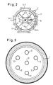
- the cross-sectional view of Fig. 3 shows that in the present case, in addition to a central manifold six evenly the circumferentially arranged manifolds 12 are provided.
- the dividing wall 8, which at the same time forms the bottom of the lock chamber 10, contains at least two individually closable bottom openings 14 distributed outside its center over the circumference.
- four bottom openings 14 are provided, as the cross-sectional view of FIG. 2 shows. From the cross-sectional views of FIGS. 2 and 3 it can also be seen that both the shaft furnace 1 and the container 3 have a circular cross-section and that the dividing wall 8 which runs obliquely downwards towards the center is formed by four circular sectors 8/1 to 8/4 is formed. A closable opening 14 is provided in each of these circular sectors.
- the circular sectors are flat, so that the partition 8 corresponds to the outer surface of a pyramid standing on the top.
- sectors of a cone shell can also be provided.
- the openings 14 are expediently to be provided with a flange in order to create flat contact surfaces for the closure members.
- the closure members for the individually closable bottom openings 14 are designed in the embodiment as flaps 15, one of which is shown in FIGS. 1 and 2 and through which the relevant bottom openings 14 can be closed from below.
- the flap 15 is shown in Fig. 1 by solid lines in the closed position and by dashed lines in the release position.
- the flaps 15 are mounted in a swivel arm 16 which is fastened on an actuating shaft 17 which can be individually rotated by a predetermined angle between the closed position and the release position by drive means, not shown.
- a neoprene seal is attached, which ensures a gas-tight closure in the closed state of the flap.
- other closing elements such as slides or valves, could also be used.
- the lock chamber 10 is closed at the top by a filling funnel 18, which is designed in the same way as the partition 8, that is, the filling funnel is also formed by four circular sectors, each of which has a closable opening 19. Individually operable flaps are also provided as closure members.
- the section indicated by IV-IV in FIG. 1 thus presents itself in the same way as section II-II, which is illustrated in FIG. 2.
- the space above the filling funnel 18 is intended for receiving the feed material to be charged in the shaft furnace. Above this space, which can be locked by a cover, a slide 20 and a conveyor belt 21 are shown schematically.
- a guide tube 22 is attached concentrically to the vertical central axis of the container 3.
- a rotary shaft 23 is rotatably and axially displaceably mounted. The drives for these two movements are arranged at the upper end of the rotary shaft and are not shown.
- a leveling rod 24 is fastened, which is rotated when the shaft rotates and which is raised and lowered within the distribution chamber 9 when the shaft is raised and lowered.
- a window 25 is provided in the container wall, through which the loading surface forming in the distribution chamber 9 can be observed.
- the feed material 7 drops within the shaft furnace and to the same extent further load material is fed from the distributor chamber 9 via the distributor pipes 12, so that the feed profile 6 in the shaft furnace is always kept at approximately the same height.
- the leveling rod 24 had been raised after the previous filling of the distribution chamber 9 and was placed on the loading surface 26 in the distribution chamber 9. As the loading surface 26 sinks in the distribution chamber, the leveling bar 24 resting thereon and the rotary shaft 23 also decrease. This lowering movement can be used as an indication of the fill level in the distribution chamber 9.
- the shaft furnace has a one-sided furnace passage, that is to say the feed material is consumed faster on the right side of the furnace than on the left side in the case shown.
- the furnace operation can thus be influenced in the desired manner.
- the leveling rod 24 it is also possible to level and mix the feed material introduced into the distribution chamber 9 from the lock chamber 10. Such a leveling is desirable in order to be able to better determine uneven sinking movements when the feed material sinks.
- the leveling rod When filling material from the lock chamber 10, the leveling rod, by means of which the minimum height in the distribution chamber has previously been detected, is located on a level below the freshly refilled material.
- a good mixing and leveling of the refilled material is achieved by means of a rotary movement which can take place in both directions and a slow lifting movement of the rotary shaft 23. After this mixing and leveling process, the rotary shaft 23 is raised and lowered onto the loading surface, so that the lowering movement of the rotating shaft with the feed material in the distributor chamber 9 can be used to monitor the filling level in this chamber.
Landscapes
- Engineering & Computer Science (AREA)
- Mechanical Engineering (AREA)
- General Engineering & Computer Science (AREA)
- Chemical & Material Sciences (AREA)
- Manufacturing & Machinery (AREA)
- Materials Engineering (AREA)
- Metallurgy (AREA)
- Organic Chemistry (AREA)
- Vertical, Hearth, Or Arc Furnaces (AREA)
- Tunnel Furnaces (AREA)
- Baking, Grill, Roasting (AREA)
- Processing And Handling Of Plastics And Other Materials For Molding In General (AREA)
- Electric Stoves And Ranges (AREA)
- Package Specialized In Special Use (AREA)
- Electric Ovens (AREA)
- Manufacture Of Iron (AREA)
- Discharge Heating (AREA)
- Blast Furnaces (AREA)
Priority Applications (1)
| Application Number | Priority Date | Filing Date | Title |
|---|---|---|---|
| AT89118813T ATE89319T1 (de) | 1988-10-13 | 1989-10-10 | Beschickungseinrichtung fuer schachtoefen, insbesondere hochoefen. |
Applications Claiming Priority (2)
| Application Number | Priority Date | Filing Date | Title |
|---|---|---|---|
| DE3834969A DE3834969A1 (de) | 1988-10-13 | 1988-10-13 | Beschickungseinrichtung fuer schachtoefen, insbesondere hochoefen |
| DE3834969 | 1988-10-13 |
Publications (2)
| Publication Number | Publication Date |
|---|---|
| EP0363906A1 EP0363906A1 (de) | 1990-04-18 |
| EP0363906B1 true EP0363906B1 (de) | 1993-05-12 |
Family
ID=6365087
Family Applications (1)
| Application Number | Title | Priority Date | Filing Date |
|---|---|---|---|
| EP89118813A Expired - Lifetime EP0363906B1 (de) | 1988-10-13 | 1989-10-10 | Beschickungseinrichtung für Schachtöfen, insbesondere Hochöfen |
Country Status (7)
| Country | Link |
|---|---|
| US (1) | US4949940A (pt) |
| EP (1) | EP0363906B1 (pt) |
| AT (1) | ATE89319T1 (pt) |
| BR (1) | BR8905179A (pt) |
| DE (2) | DE3834969A1 (pt) |
| ES (1) | ES2044010T3 (pt) |
| PT (1) | PT91969B (pt) |
Families Citing this family (7)
| Publication number | Priority date | Publication date | Assignee | Title |
|---|---|---|---|---|
| AT396482B (de) * | 1991-05-29 | 1993-09-27 | Voest Alpine Ind Anlagen | Anlage mit einem schacht, insbesondere reduktionsschachtofen |
| US5494263A (en) * | 1994-03-07 | 1996-02-27 | Centro De Investigacion Y Asistencia Tecnica Del Edo. De Qro, A.C. | System for solid material charging into vertical reactors by electronic control of the exhaust gases |
| DE10327276A1 (de) | 2003-06-17 | 2005-01-05 | Z & J Technologies Gmbh | Vorrichtung zum Verschließen oder Öffnen einer Öffnung, insbesondere Bodenöffnung eines Materialbunkers für einen Hochofen |
| US7467559B2 (en) * | 2006-10-09 | 2008-12-23 | Schlumberger Technology Corporation | Apparatus and methods for sample handling and rheology analysis |
| MD3959C2 (ro) * | 2007-07-04 | 2010-04-30 | Dinano Ecotechnology Llc | Dispozitiv de încărcare a instalaţiei pentru prelucrarea materiei prime ce conţine carbon |
| KR102270393B1 (ko) * | 2019-10-22 | 2021-06-30 | 에스케이실트론 주식회사 | 원료 공급 유닛, 이를 포함하는 실리콘 단결정 잉곳의 성장 장치 및 원료 공급 방법 |
| KR20220154452A (ko) * | 2021-05-13 | 2022-11-22 | 현대자동차주식회사 | 원료분말용 호퍼 및 이를 이용한 원료분말 이송방법 |
Family Cites Families (13)
| Publication number | Priority date | Publication date | Assignee | Title |
|---|---|---|---|---|
| GB311506A (en) * | 1928-03-20 | 1929-05-16 | William Thomas Bell | Improved construction of apparatus for feeding coal and like dust to a burner for burning in a furnace or the like |
| DE749557C (de) * | 1940-05-05 | 1944-11-25 | Beschickungsvorrichtung fuer Hochoefen | |
| DE1035367B (de) * | 1952-07-25 | 1958-07-31 | Ko We Niederschachtofen Ges M | Beschickungseinrichtung fuer Schachtoefen |
| DE1263040B (de) * | 1963-09-19 | 1968-03-14 | Demag Ag | Gichtverschluss mit Verteilvorrichtung fuer das Begichtungsgut fuer insbesondere im Durchmesser grosse, im Hochdruckverfahren betriebene Hochoefen |
| GB1174068A (en) * | 1966-11-08 | 1969-12-10 | Ishikawajima Harima Heavy Ind | Furnace Top Charging Equipment |
| DE1608301C3 (de) * | 1968-03-06 | 1974-01-03 | Demag Ag, 4100 Duisburg | Verfahren und Gichtverschluß zum Beschicken von Schachtofen, insbesondere von im Hochdruck betriebenen Hochöfen |
| DE1803560A1 (de) * | 1968-10-17 | 1970-05-27 | Demag Ag | Verfahren und Gichtverschluss zum Begichten von Schachtoefen,insbesondere von Hochoefen |
| DE7535021U (de) * | 1975-11-04 | 1977-08-11 | Gutehoffnungshuette Sterkade Ag, 4200 Oberhausen | Vorrichtung an einem schachtofen |
| US4029220A (en) * | 1975-11-28 | 1977-06-14 | Greaves Melvin J | Distributor means for charging particulate material into receptacles |
| SU850669A1 (ru) * | 1978-11-21 | 1981-07-30 | Украинский Государственный Институтпо Проектированию Металлургическихзаводов | Загрузочное устройство доменной печи |
| SE441865B (sv) * | 1981-03-10 | 1985-11-11 | Skf Steel Eng Ab | Anordning for att uppifran tillfora styckeformigt material till ett schakt |
| AT382712B (de) * | 1985-05-10 | 1987-04-10 | Voest Alpine Ag | Beschickungsvorrichtung fuer einen schachtofen zum brennen von karbonathaltigem, mineralischem brenngut |
| LU86336A1 (fr) * | 1986-03-04 | 1987-11-11 | Wurth Paul Sa | Installation de chargement d'un four a cuve |
-
1988
- 1988-10-13 DE DE3834969A patent/DE3834969A1/de not_active Withdrawn
-
1989
- 1989-10-10 EP EP89118813A patent/EP0363906B1/de not_active Expired - Lifetime
- 1989-10-10 DE DE8989118813T patent/DE58904333D1/de not_active Expired - Fee Related
- 1989-10-10 ES ES89118813T patent/ES2044010T3/es not_active Expired - Lifetime
- 1989-10-10 AT AT89118813T patent/ATE89319T1/de not_active IP Right Cessation
- 1989-10-12 PT PT91969A patent/PT91969B/pt not_active IP Right Cessation
- 1989-10-12 US US07/420,289 patent/US4949940A/en not_active Expired - Fee Related
- 1989-10-12 BR BR898905179A patent/BR8905179A/pt not_active Application Discontinuation
Also Published As
| Publication number | Publication date |
|---|---|
| EP0363906A1 (de) | 1990-04-18 |
| PT91969A (pt) | 1990-04-30 |
| US4949940A (en) | 1990-08-21 |
| DE3834969A1 (de) | 1990-04-19 |
| ATE89319T1 (de) | 1993-05-15 |
| ES2044010T3 (es) | 1994-01-01 |
| BR8905179A (pt) | 1990-05-15 |
| PT91969B (pt) | 1995-08-09 |
| DE58904333D1 (de) | 1993-06-17 |
Similar Documents
| Publication | Publication Date | Title |
|---|---|---|
| DE102010035893B3 (de) | Beschickungsvorrichtung für Glasschmelzanlagen und Verfahren zum Einlegen von partikelförmigem Beschickungsgut | |
| DE2418371C3 (de) | Gichtverteiler für Hochöfen | |
| DE2404647B2 (de) | Beschickungseinrichtung fuer hochoefen | |
| EP0363906B1 (de) | Beschickungseinrichtung für Schachtöfen, insbesondere Hochöfen | |
| EP0003247B1 (de) | Glasschmelzofen | |
| DE1458762A1 (de) | Schachtofen fuer die Direktreduktion von Eisenerz | |
| DE3204315C2 (de) | Beschickungsanlage für Gleichstrom-Regenerativ-Schachtöfen zum Brennen von Kalkstein und ähnlichen mineralischen Rohstoffen | |
| DE4413864C2 (de) | Adsorptionsmittelreaktor mit einer Mehrzahl von Abzugstrichtern zum Austragen von schüttfähigem Adsorptionsmittel | |
| EP0303864B1 (de) | Silo für staubförmige und feinkörnige Schüttgüter | |
| DE2500784C3 (de) | Doppelstock-Mischsilo | |
| EP1439360B1 (de) | Verfahren zum Brennen eines mineralischen Materialgemischs | |
| DE890559C (de) | Beschickungsvorrichtung fuer Feuerungen mit grosser Rostbreite | |
| DE3906415A1 (de) | Vorrichtung und verfahren zum beschicken einer schachtofenanlage | |
| DE3314943A1 (de) | Vorrichtung und verfahren zur beschickung elektrothermischer schmelzoefen | |
| DE10234520B4 (de) | Vorrichtung zur Bandbegichtung eines Hochofens | |
| DE1758947B2 (de) | Zweiglocken-Hochofengichtverschluß | |
| DE1035367B (de) | Beschickungseinrichtung fuer Schachtoefen | |
| DE3243222C2 (pt) | ||
| DE1758156B1 (de) | Vorrichtung zum Beschicken von Schachtoefen | |
| AT354492B (de) | Rotationsschleudermaschine | |
| DE1120351B (de) | Abfuellvorrichtung fuer schuettbare Fuellgueter aller Art | |
| DE598012C (de) | Vorrichtung zur Fuehrung von Gasen in bewegten, vorzugsweise umlaufenden Behaeltern, Trommeln, Drehrohroefen o. dgl. | |
| DE1432034C (de) | Vorrichtung zum Homogenisieren von trockenem, feingemahlenem Pulver und Verfahren zum Betrieb dieser Vorrichtung | |
| AT216949B (de) | Einrichtung zur Beschickung von Schachtöfen | |
| CH678847A5 (pt) |
Legal Events
| Date | Code | Title | Description |
|---|---|---|---|
| PUAI | Public reference made under article 153(3) epc to a published international application that has entered the european phase |
Free format text: ORIGINAL CODE: 0009012 |
|
| AK | Designated contracting states |
Kind code of ref document: A1 Designated state(s): AT BE CH DE ES FR GB GR IT LI LU NL SE |
|
| 17P | Request for examination filed |
Effective date: 19900516 |
|
| 17Q | First examination report despatched |
Effective date: 19920915 |
|
| GRAA | (expected) grant |
Free format text: ORIGINAL CODE: 0009210 |
|
| AK | Designated contracting states |
Kind code of ref document: B1 Designated state(s): AT BE CH DE ES FR GB GR IT LI LU NL SE |
|
| PG25 | Lapsed in a contracting state [announced via postgrant information from national office to epo] |
Ref country code: SE Effective date: 19930512 Ref country code: NL Effective date: 19930512 Ref country code: GR Free format text: LAPSE BECAUSE OF FAILURE TO SUBMIT A TRANSLATION OF THE DESCRIPTION OR TO PAY THE FEE WITHIN THE PRESCRIBED TIME-LIMIT Effective date: 19930512 |
|
| REF | Corresponds to: |
Ref document number: 89319 Country of ref document: AT Date of ref document: 19930515 Kind code of ref document: T |
|
| REF | Corresponds to: |
Ref document number: 58904333 Country of ref document: DE Date of ref document: 19930617 |
|
| ET | Fr: translation filed | ||
| ITF | It: translation for a ep patent filed |
Owner name: UFFICIO BREVETTI RICCARDI & C. |
|
| GBT | Gb: translation of ep patent filed (gb section 77(6)(a)/1977) |
Effective date: 19930719 |
|
| PGFP | Annual fee paid to national office [announced via postgrant information from national office to epo] |
Ref country code: CH Payment date: 19930913 Year of fee payment: 5 |
|
| NLV1 | Nl: lapsed or annulled due to failure to fulfill the requirements of art. 29p and 29m of the patents act | ||
| EPTA | Lu: last paid annual fee | ||
| REG | Reference to a national code |
Ref country code: ES Ref legal event code: FG2A Ref document number: 2044010 Country of ref document: ES Kind code of ref document: T3 |
|
| ITTA | It: last paid annual fee | ||
| PG25 | Lapsed in a contracting state [announced via postgrant information from national office to epo] |
Ref country code: LI Effective date: 19941031 Ref country code: CH Effective date: 19941031 |
|
| REG | Reference to a national code |
Ref country code: CH Ref legal event code: PL |
|
| PGFP | Annual fee paid to national office [announced via postgrant information from national office to epo] |
Ref country code: LU Payment date: 19960901 Year of fee payment: 8 |
|
| PGFP | Annual fee paid to national office [announced via postgrant information from national office to epo] |
Ref country code: GB Payment date: 19960916 Year of fee payment: 8 |
|
| PGFP | Annual fee paid to national office [announced via postgrant information from national office to epo] |
Ref country code: FR Payment date: 19960920 Year of fee payment: 8 |
|
| PGFP | Annual fee paid to national office [announced via postgrant information from national office to epo] |
Ref country code: AT Payment date: 19960923 Year of fee payment: 8 |
|
| PGFP | Annual fee paid to national office [announced via postgrant information from national office to epo] |
Ref country code: BE Payment date: 19960924 Year of fee payment: 8 |
|
| PGFP | Annual fee paid to national office [announced via postgrant information from national office to epo] |
Ref country code: ES Payment date: 19961018 Year of fee payment: 8 |
|
| PGFP | Annual fee paid to national office [announced via postgrant information from national office to epo] |
Ref country code: DE Payment date: 19961118 Year of fee payment: 8 |
|
| PG25 | Lapsed in a contracting state [announced via postgrant information from national office to epo] |
Ref country code: LU Free format text: LAPSE BECAUSE OF NON-PAYMENT OF DUE FEES Effective date: 19971010 Ref country code: GB Free format text: LAPSE BECAUSE OF NON-PAYMENT OF DUE FEES Effective date: 19971010 Ref country code: AT Free format text: LAPSE BECAUSE OF NON-PAYMENT OF DUE FEES Effective date: 19971010 |
|
| PG25 | Lapsed in a contracting state [announced via postgrant information from national office to epo] |
Ref country code: ES Free format text: LAPSE BECAUSE OF THE APPLICANT RENOUNCES Effective date: 19971011 |
|
| PG25 | Lapsed in a contracting state [announced via postgrant information from national office to epo] |
Ref country code: FR Free format text: THE PATENT HAS BEEN ANNULLED BY A DECISION OF A NATIONAL AUTHORITY Effective date: 19971031 Ref country code: BE Free format text: LAPSE BECAUSE OF NON-PAYMENT OF DUE FEES Effective date: 19971031 |
|
| BERE | Be: lapsed |
Owner name: KORTEC A.G. Effective date: 19971031 |
|
| GBPC | Gb: european patent ceased through non-payment of renewal fee |
Effective date: 19971010 |
|
| PG25 | Lapsed in a contracting state [announced via postgrant information from national office to epo] |
Ref country code: DE Free format text: LAPSE BECAUSE OF NON-PAYMENT OF DUE FEES Effective date: 19980701 |
|
| REG | Reference to a national code |
Ref country code: FR Ref legal event code: ST |
|
| REG | Reference to a national code |
Ref country code: ES Ref legal event code: FD2A Effective date: 20001102 |
|
| PG25 | Lapsed in a contracting state [announced via postgrant information from national office to epo] |
Ref country code: IT Free format text: LAPSE BECAUSE OF NON-PAYMENT OF DUE FEES;WARNING: LAPSES OF ITALIAN PATENTS WITH EFFECTIVE DATE BEFORE 2007 MAY HAVE OCCURRED AT ANY TIME BEFORE 2007. THE CORRECT EFFECTIVE DATE MAY BE DIFFERENT FROM THE ONE RECORDED. Effective date: 20051010 |
|
| PLBE | No opposition filed within time limit |
Free format text: ORIGINAL CODE: 0009261 |
|
| STAA | Information on the status of an ep patent application or granted ep patent |
Free format text: STATUS: NO OPPOSITION FILED WITHIN TIME LIMIT |