EP0360941B1 - Zersetzung von flüchtigen, halogenierten organischen Verbindungen in Gasen und wässrigen Lösungen - Google Patents
Zersetzung von flüchtigen, halogenierten organischen Verbindungen in Gasen und wässrigen Lösungen Download PDFInfo
- Publication number
- EP0360941B1 EP0360941B1 EP88309759A EP88309759A EP0360941B1 EP 0360941 B1 EP0360941 B1 EP 0360941B1 EP 88309759 A EP88309759 A EP 88309759A EP 88309759 A EP88309759 A EP 88309759A EP 0360941 B1 EP0360941 B1 EP 0360941B1
- Authority
- EP
- European Patent Office
- Prior art keywords
- ozone
- adsorbent bed
- gases
- volatile organic
- porous adsorbent
- Prior art date
- Legal status (The legal status is an assumption and is not a legal conclusion. Google has not performed a legal analysis and makes no representation as to the accuracy of the status listed.)
- Expired - Lifetime
Links
- 150000001875 compounds Chemical class 0.000 title claims abstract description 93
- 239000007789 gas Substances 0.000 title claims abstract description 86
- 239000007864 aqueous solution Substances 0.000 title claims abstract description 25
- VYPSYNLAJGMNEJ-UHFFFAOYSA-N Silicium dioxide Chemical compound O=[Si]=O VYPSYNLAJGMNEJ-UHFFFAOYSA-N 0.000 claims abstract description 86
- CBENFWSGALASAD-UHFFFAOYSA-N Ozone Chemical compound [O-][O+]=O CBENFWSGALASAD-UHFFFAOYSA-N 0.000 claims abstract description 75
- 229910002027 silica gel Inorganic materials 0.000 claims abstract description 66
- 239000000741 silica gel Substances 0.000 claims abstract description 66
- 239000000243 solution Substances 0.000 claims abstract description 39
- 239000003463 adsorbent Substances 0.000 claims abstract description 38
- 230000001678 irradiating effect Effects 0.000 claims abstract description 17
- 238000000034 method Methods 0.000 claims abstract description 15
- 239000012855 volatile organic compound Substances 0.000 claims abstract description 10
- 238000001784 detoxification Methods 0.000 claims description 78
- XLYOFNOQVPJJNP-UHFFFAOYSA-N water Substances O XLYOFNOQVPJJNP-UHFFFAOYSA-N 0.000 claims description 57
- 238000000354 decomposition reaction Methods 0.000 claims description 17
- 239000000203 mixture Substances 0.000 claims description 16
- 239000010453 quartz Substances 0.000 claims description 12
- 150000002894 organic compounds Chemical class 0.000 claims description 11
- 238000006243 chemical reaction Methods 0.000 claims description 7
- 238000010438 heat treatment Methods 0.000 claims description 7
- 230000009467 reduction Effects 0.000 claims description 6
- 229920006395 saturated elastomer Polymers 0.000 claims description 4
- 230000005855 radiation Effects 0.000 claims description 3
- 239000002250 absorbent Substances 0.000 claims description 2
- 230000002745 absorbent Effects 0.000 claims description 2
- 238000004064 recycling Methods 0.000 claims description 2
- UBOXGVDOUJQMTN-UHFFFAOYSA-N trichloroethylene Natural products ClCC(Cl)Cl UBOXGVDOUJQMTN-UHFFFAOYSA-N 0.000 description 67
- XSTXAVWGXDQKEL-UHFFFAOYSA-N Trichloroethylene Chemical group ClC=C(Cl)Cl XSTXAVWGXDQKEL-UHFFFAOYSA-N 0.000 description 64
- 238000012360 testing method Methods 0.000 description 34
- YMWUJEATGCHHMB-UHFFFAOYSA-N Dichloromethane Chemical compound ClCCl YMWUJEATGCHHMB-UHFFFAOYSA-N 0.000 description 30
- 238000002474 experimental method Methods 0.000 description 28
- 230000003647 oxidation Effects 0.000 description 26
- 238000007254 oxidation reaction Methods 0.000 description 26
- ISWSIDIOOBJBQZ-UHFFFAOYSA-N Phenol Chemical compound OC1=CC=CC=C1 ISWSIDIOOBJBQZ-UHFFFAOYSA-N 0.000 description 24
- 235000012239 silicon dioxide Nutrition 0.000 description 15
- 239000002351 wastewater Substances 0.000 description 14
- 230000001965 increasing effect Effects 0.000 description 12
- IJGRMHOSHXDMSA-UHFFFAOYSA-N Atomic nitrogen Chemical compound N#N IJGRMHOSHXDMSA-UHFFFAOYSA-N 0.000 description 11
- BZHJMEDXRYGGRV-UHFFFAOYSA-N Vinyl chloride Chemical compound ClC=C BZHJMEDXRYGGRV-UHFFFAOYSA-N 0.000 description 11
- 230000003028 elevating effect Effects 0.000 description 9
- 239000011521 glass Substances 0.000 description 8
- 230000000694 effects Effects 0.000 description 7
- 231100000331 toxic Toxicity 0.000 description 7
- 230000002588 toxic effect Effects 0.000 description 7
- BDAGIHXWWSANSR-UHFFFAOYSA-N methanoic acid Natural products OC=O BDAGIHXWWSANSR-UHFFFAOYSA-N 0.000 description 6
- VLKZOEOYAKHREP-UHFFFAOYSA-N n-Hexane Chemical compound CCCCCC VLKZOEOYAKHREP-UHFFFAOYSA-N 0.000 description 6
- 231100000167 toxic agent Toxicity 0.000 description 5
- QPFMBZIOSGYJDE-UHFFFAOYSA-N 1,1,2,2-tetrachloroethane Chemical compound ClC(Cl)C(Cl)Cl QPFMBZIOSGYJDE-UHFFFAOYSA-N 0.000 description 4
- GATVIKZLVQHOMN-UHFFFAOYSA-N Chlorodibromomethane Chemical compound ClC(Br)Br GATVIKZLVQHOMN-UHFFFAOYSA-N 0.000 description 4
- QVGXLLKOCUKJST-UHFFFAOYSA-N atomic oxygen Chemical compound [O] QVGXLLKOCUKJST-UHFFFAOYSA-N 0.000 description 4
- DIKBFYAXUHHXCS-UHFFFAOYSA-N bromoform Chemical compound BrC(Br)Br DIKBFYAXUHHXCS-UHFFFAOYSA-N 0.000 description 4
- GZUXJHMPEANEGY-UHFFFAOYSA-N bromomethane Chemical compound BrC GZUXJHMPEANEGY-UHFFFAOYSA-N 0.000 description 4
- 239000003610 charcoal Substances 0.000 description 4
- MVPPADPHJFYWMZ-UHFFFAOYSA-N chlorobenzene Chemical compound ClC1=CC=CC=C1 MVPPADPHJFYWMZ-UHFFFAOYSA-N 0.000 description 4
- NEHMKBQYUWJMIP-UHFFFAOYSA-N chloromethane Chemical compound ClC NEHMKBQYUWJMIP-UHFFFAOYSA-N 0.000 description 4
- 229910052681 coesite Inorganic materials 0.000 description 4
- 229910052906 cristobalite Inorganic materials 0.000 description 4
- 229940117389 dichlorobenzene Drugs 0.000 description 4
- 229910052757 nitrogen Inorganic materials 0.000 description 4
- 239000001301 oxygen Substances 0.000 description 4
- 229910052760 oxygen Inorganic materials 0.000 description 4
- 239000000377 silicon dioxide Substances 0.000 description 4
- 229910052682 stishovite Inorganic materials 0.000 description 4
- VZGDMQKNWNREIO-UHFFFAOYSA-N tetrachloromethane Chemical compound ClC(Cl)(Cl)Cl VZGDMQKNWNREIO-UHFFFAOYSA-N 0.000 description 4
- 229910052905 tridymite Inorganic materials 0.000 description 4
- OSWFIVFLDKOXQC-UHFFFAOYSA-N 4-(3-methoxyphenyl)aniline Chemical compound COC1=CC=CC(C=2C=CC(N)=CC=2)=C1 OSWFIVFLDKOXQC-UHFFFAOYSA-N 0.000 description 3
- 241000894006 Bacteria Species 0.000 description 3
- WSFSSNUMVMOOMR-UHFFFAOYSA-N Formaldehyde Chemical compound O=C WSFSSNUMVMOOMR-UHFFFAOYSA-N 0.000 description 3
- KFZMGEQAYNKOFK-UHFFFAOYSA-N Isopropanol Chemical compound CC(C)O KFZMGEQAYNKOFK-UHFFFAOYSA-N 0.000 description 3
- MUBZPKHOEPUJKR-UHFFFAOYSA-N Oxalic acid Chemical compound OC(=O)C(O)=O MUBZPKHOEPUJKR-UHFFFAOYSA-N 0.000 description 3
- 229910052799 carbon Inorganic materials 0.000 description 3
- KRKNYBCHXYNGOX-UHFFFAOYSA-N citric acid Chemical compound OC(=O)CC(O)(C(O)=O)CC(O)=O KRKNYBCHXYNGOX-UHFFFAOYSA-N 0.000 description 3
- 229910001873 dinitrogen Inorganic materials 0.000 description 3
- 235000019253 formic acid Nutrition 0.000 description 3
- BAUYGSIQEAFULO-UHFFFAOYSA-L iron(2+) sulfate (anhydrous) Chemical compound [Fe+2].[O-]S([O-])(=O)=O BAUYGSIQEAFULO-UHFFFAOYSA-L 0.000 description 3
- 229910000359 iron(II) sulfate Inorganic materials 0.000 description 3
- 239000003973 paint Substances 0.000 description 3
- 238000000746 purification Methods 0.000 description 3
- PPKPKFIWDXDAGC-NSCUHMNNSA-N (e)-1,2-dichloroprop-1-ene Chemical group C\C(Cl)=C/Cl PPKPKFIWDXDAGC-NSCUHMNNSA-N 0.000 description 2
- SCYULBFZEHDVBN-UHFFFAOYSA-N 1,1-Dichloroethane Chemical compound CC(Cl)Cl SCYULBFZEHDVBN-UHFFFAOYSA-N 0.000 description 2
- LGXVIGDEPROXKC-UHFFFAOYSA-N 1,1-dichloroethene Chemical group ClC(Cl)=C LGXVIGDEPROXKC-UHFFFAOYSA-N 0.000 description 2
- PAAZPARNPHGIKF-UHFFFAOYSA-N 1,2-dibromoethane Chemical compound BrCCBr PAAZPARNPHGIKF-UHFFFAOYSA-N 0.000 description 2
- KNKRKFALVUDBJE-UHFFFAOYSA-N 1,2-dichloropropane Chemical compound CC(Cl)CCl KNKRKFALVUDBJE-UHFFFAOYSA-N 0.000 description 2
- NLXGURFLBLRZRO-UHFFFAOYSA-N 1-chloro-2-(2-chloroethoxymethoxy)ethane Chemical compound ClCCOCOCCCl NLXGURFLBLRZRO-UHFFFAOYSA-N 0.000 description 2
- BULHJTXRZFEUDQ-UHFFFAOYSA-N 2-chloro-2-(2-chloropropan-2-yloxy)propane Chemical compound CC(C)(Cl)OC(C)(C)Cl BULHJTXRZFEUDQ-UHFFFAOYSA-N 0.000 description 2
- REEBWSYYNPPSKV-UHFFFAOYSA-N 3-[(4-formylphenoxy)methyl]thiophene-2-carbonitrile Chemical compound C1=CC(C=O)=CC=C1OCC1=C(C#N)SC=C1 REEBWSYYNPPSKV-UHFFFAOYSA-N 0.000 description 2
- ZNSMNVMLTJELDZ-UHFFFAOYSA-N Bis(2-chloroethyl)ether Chemical compound ClCCOCCCl ZNSMNVMLTJELDZ-UHFFFAOYSA-N 0.000 description 2
- OKTJSMMVPCPJKN-UHFFFAOYSA-N Carbon Chemical compound [C] OKTJSMMVPCPJKN-UHFFFAOYSA-N 0.000 description 2
- PXHVJJICTQNCMI-UHFFFAOYSA-N Nickel Chemical compound [Ni] PXHVJJICTQNCMI-UHFFFAOYSA-N 0.000 description 2
- CYTYCFOTNPOANT-UHFFFAOYSA-N Perchloroethylene Chemical group ClC(Cl)=C(Cl)Cl CYTYCFOTNPOANT-UHFFFAOYSA-N 0.000 description 2
- 230000009471 action Effects 0.000 description 2
- 150000001298 alcohols Chemical class 0.000 description 2
- XAGFODPZIPBFFR-UHFFFAOYSA-N aluminium Chemical compound [Al] XAGFODPZIPBFFR-UHFFFAOYSA-N 0.000 description 2
- 229910052782 aluminium Inorganic materials 0.000 description 2
- HRQGCQVOJVTVLU-UHFFFAOYSA-N bis(chloromethyl) ether Chemical compound ClCOCCl HRQGCQVOJVTVLU-UHFFFAOYSA-N 0.000 description 2
- XNNQFQFUQLJSQT-UHFFFAOYSA-N bromo(trichloro)methane Chemical compound ClC(Cl)(Cl)Br XNNQFQFUQLJSQT-UHFFFAOYSA-N 0.000 description 2
- 229950005228 bromoform Drugs 0.000 description 2
- 239000003054 catalyst Substances 0.000 description 2
- WQJDQHSMWRYTJX-UHFFFAOYSA-N chloroform;1,2-dichlorobenzene Chemical compound ClC(Cl)Cl.ClC1=CC=CC=C1Cl WQJDQHSMWRYTJX-UHFFFAOYSA-N 0.000 description 2
- 239000012141 concentrate Substances 0.000 description 2
- 230000006378 damage Effects 0.000 description 2
- 238000013461 design Methods 0.000 description 2
- UMNKXPULIDJLSU-UHFFFAOYSA-N dichlorofluoromethane Chemical compound FC(Cl)Cl UMNKXPULIDJLSU-UHFFFAOYSA-N 0.000 description 2
- 229940099364 dichlorofluoromethane Drugs 0.000 description 2
- 235000014113 dietary fatty acids Nutrition 0.000 description 2
- 239000003651 drinking water Substances 0.000 description 2
- 230000005670 electromagnetic radiation Effects 0.000 description 2
- 229930195729 fatty acid Natural products 0.000 description 2
- 239000000194 fatty acid Substances 0.000 description 2
- 150000004665 fatty acids Chemical class 0.000 description 2
- 239000008246 gaseous mixture Substances 0.000 description 2
- VHHHONWQHHHLTI-UHFFFAOYSA-N hexachloroethane Chemical compound ClC(Cl)(Cl)C(Cl)(Cl)Cl VHHHONWQHHHLTI-UHFFFAOYSA-N 0.000 description 2
- 229940102396 methyl bromide Drugs 0.000 description 2
- 229940050176 methyl chloride Drugs 0.000 description 2
- 238000002156 mixing Methods 0.000 description 2
- SNMVRZFUUCLYTO-UHFFFAOYSA-N n-propyl chloride Chemical compound CCCCl SNMVRZFUUCLYTO-UHFFFAOYSA-N 0.000 description 2
- 125000005608 naphthenic acid group Chemical group 0.000 description 2
- IZUPBVBPLAPZRR-UHFFFAOYSA-N pentachlorophenol Chemical compound OC1=C(Cl)C(Cl)=C(Cl)C(Cl)=C1Cl IZUPBVBPLAPZRR-UHFFFAOYSA-N 0.000 description 2
- 230000008929 regeneration Effects 0.000 description 2
- 238000011069 regeneration method Methods 0.000 description 2
- 239000000126 substance Substances 0.000 description 2
- 229950011008 tetrachloroethylene Drugs 0.000 description 2
- KFUSEUYYWQURPO-OWOJBTEDSA-N trans-1,2-dichloroethene Chemical group Cl\C=C\Cl KFUSEUYYWQURPO-OWOJBTEDSA-N 0.000 description 2
- CYRMSUTZVYGINF-UHFFFAOYSA-N trichlorofluoromethane Chemical compound FC(Cl)(Cl)Cl CYRMSUTZVYGINF-UHFFFAOYSA-N 0.000 description 2
- 229940029284 trichlorofluoromethane Drugs 0.000 description 2
- VYZAMTAEIAYCRO-UHFFFAOYSA-N Chromium Chemical compound [Cr] VYZAMTAEIAYCRO-UHFFFAOYSA-N 0.000 description 1
- RYGMFSIKBFXOCR-UHFFFAOYSA-N Copper Chemical compound [Cu] RYGMFSIKBFXOCR-UHFFFAOYSA-N 0.000 description 1
- KCXVZYZYPLLWCC-UHFFFAOYSA-N EDTA Chemical compound OC(=O)CN(CC(O)=O)CCN(CC(O)=O)CC(O)=O KCXVZYZYPLLWCC-UHFFFAOYSA-N 0.000 description 1
- HCHKCACWOHOZIP-UHFFFAOYSA-N Zinc Chemical compound [Zn] HCHKCACWOHOZIP-UHFFFAOYSA-N 0.000 description 1
- 238000003915 air pollution Methods 0.000 description 1
- 125000001931 aliphatic group Chemical group 0.000 description 1
- 230000001580 bacterial effect Effects 0.000 description 1
- 235000012206 bottled water Nutrition 0.000 description 1
- FMWLUWPQPKEARP-UHFFFAOYSA-N bromodichloromethane Chemical compound ClC(Cl)Br FMWLUWPQPKEARP-UHFFFAOYSA-N 0.000 description 1
- HKPHPIREJKHECO-UHFFFAOYSA-N butachlor Chemical compound CCCCOCN(C(=O)CCl)C1=C(CC)C=CC=C1CC HKPHPIREJKHECO-UHFFFAOYSA-N 0.000 description 1
- 239000006227 byproduct Substances 0.000 description 1
- 229910052793 cadmium Inorganic materials 0.000 description 1
- BDOSMKKIYDKNTQ-UHFFFAOYSA-N cadmium atom Chemical compound [Cd] BDOSMKKIYDKNTQ-UHFFFAOYSA-N 0.000 description 1
- 238000003421 catalytic decomposition reaction Methods 0.000 description 1
- 230000003197 catalytic effect Effects 0.000 description 1
- 238000001311 chemical methods and process Methods 0.000 description 1
- HRYZWHHZPQKTII-UHFFFAOYSA-N chloroethane Chemical compound CCCl HRYZWHHZPQKTII-UHFFFAOYSA-N 0.000 description 1
- 229910052804 chromium Inorganic materials 0.000 description 1
- 239000011651 chromium Substances 0.000 description 1
- 229910052802 copper Inorganic materials 0.000 description 1
- 239000010949 copper Substances 0.000 description 1
- 125000004122 cyclic group Chemical group 0.000 description 1
- -1 dichloro dichlorobromomethane Chemical compound 0.000 description 1
- 238000009792 diffusion process Methods 0.000 description 1
- 239000006185 dispersion Substances 0.000 description 1
- 235000020188 drinking water Nutrition 0.000 description 1
- 238000005108 dry cleaning Methods 0.000 description 1
- 230000007613 environmental effect Effects 0.000 description 1
- 229960003750 ethyl chloride Drugs 0.000 description 1
- 239000006260 foam Substances 0.000 description 1
- JLYXXMFPNIAWKQ-GNIYUCBRSA-N gamma-hexachlorocyclohexane Chemical compound Cl[C@H]1[C@H](Cl)[C@@H](Cl)[C@@H](Cl)[C@H](Cl)[C@H]1Cl JLYXXMFPNIAWKQ-GNIYUCBRSA-N 0.000 description 1
- JLYXXMFPNIAWKQ-UHFFFAOYSA-N gamma-hexachlorocyclohexane Natural products ClC1C(Cl)C(Cl)C(Cl)C(Cl)C1Cl JLYXXMFPNIAWKQ-UHFFFAOYSA-N 0.000 description 1
- 238000004817 gas chromatography Methods 0.000 description 1
- 239000000499 gel Substances 0.000 description 1
- 239000011491 glass wool Substances 0.000 description 1
- CKAPSXZOOQJIBF-UHFFFAOYSA-N hexachlorobenzene Chemical compound ClC1=C(Cl)C(Cl)=C(Cl)C(Cl)=C1Cl CKAPSXZOOQJIBF-UHFFFAOYSA-N 0.000 description 1
- 239000003295 industrial effluent Substances 0.000 description 1
- 229960002809 lindane Drugs 0.000 description 1
- 239000000463 material Substances 0.000 description 1
- 238000012986 modification Methods 0.000 description 1
- 230000004048 modification Effects 0.000 description 1
- 229910052759 nickel Inorganic materials 0.000 description 1
- 235000006408 oxalic acid Nutrition 0.000 description 1
- 238000006385 ozonation reaction Methods 0.000 description 1
- 150000003071 polychlorinated biphenyls Chemical class 0.000 description 1
- 239000000047 product Substances 0.000 description 1
- 229920002379 silicone rubber Polymers 0.000 description 1
- 239000004945 silicone rubber Substances 0.000 description 1
- 239000002904 solvent Substances 0.000 description 1
- 238000001179 sorption measurement Methods 0.000 description 1
- 229910001220 stainless steel Inorganic materials 0.000 description 1
- 239000010935 stainless steel Substances 0.000 description 1
- 238000006467 substitution reaction Methods 0.000 description 1
- 239000002341 toxic gas Substances 0.000 description 1
- 231100000419 toxicity Toxicity 0.000 description 1
- 230000001988 toxicity Effects 0.000 description 1
- 238000009834 vaporization Methods 0.000 description 1
- 230000008016 vaporization Effects 0.000 description 1
- 238000005406 washing Methods 0.000 description 1
- 235000020681 well water Nutrition 0.000 description 1
- 239000002349 well water Substances 0.000 description 1
- 239000011701 zinc Substances 0.000 description 1
- 229910052725 zinc Inorganic materials 0.000 description 1
Images


Classifications
-
- C—CHEMISTRY; METALLURGY
- C02—TREATMENT OF WATER, WASTE WATER, SEWAGE, OR SLUDGE
- C02F—TREATMENT OF WATER, WASTE WATER, SEWAGE, OR SLUDGE
- C02F1/00—Treatment of water, waste water, or sewage
- C02F1/72—Treatment of water, waste water, or sewage by oxidation
- C02F1/78—Treatment of water, waste water, or sewage by oxidation with ozone
-
- A—HUMAN NECESSITIES
- A62—LIFE-SAVING; FIRE-FIGHTING
- A62D—CHEMICAL MEANS FOR EXTINGUISHING FIRES OR FOR COMBATING OR PROTECTING AGAINST HARMFUL CHEMICAL AGENTS; CHEMICAL MATERIALS FOR USE IN BREATHING APPARATUS
- A62D3/00—Processes for making harmful chemical substances harmless or less harmful, by effecting a chemical change in the substances
- A62D3/10—Processes for making harmful chemical substances harmless or less harmful, by effecting a chemical change in the substances by subjecting to electric or wave energy or particle or ionizing radiation
- A62D3/17—Processes for making harmful chemical substances harmless or less harmful, by effecting a chemical change in the substances by subjecting to electric or wave energy or particle or ionizing radiation to electromagnetic radiation, e.g. emitted by a laser
- A62D3/176—Ultraviolet radiations, i.e. radiation having a wavelength of about 3nm to 400nm
-
- A—HUMAN NECESSITIES
- A62—LIFE-SAVING; FIRE-FIGHTING
- A62D—CHEMICAL MEANS FOR EXTINGUISHING FIRES OR FOR COMBATING OR PROTECTING AGAINST HARMFUL CHEMICAL AGENTS; CHEMICAL MATERIALS FOR USE IN BREATHING APPARATUS
- A62D3/00—Processes for making harmful chemical substances harmless or less harmful, by effecting a chemical change in the substances
- A62D3/30—Processes for making harmful chemical substances harmless or less harmful, by effecting a chemical change in the substances by reacting with chemical agents
- A62D3/38—Processes for making harmful chemical substances harmless or less harmful, by effecting a chemical change in the substances by reacting with chemical agents by oxidation; by combustion
-
- B—PERFORMING OPERATIONS; TRANSPORTING
- B01—PHYSICAL OR CHEMICAL PROCESSES OR APPARATUS IN GENERAL
- B01D—SEPARATION
- B01D53/00—Separation of gases or vapours; Recovering vapours of volatile solvents from gases; Chemical or biological purification of waste gases, e.g. engine exhaust gases, smoke, fumes, flue gases, aerosols
- B01D53/34—Chemical or biological purification of waste gases
- B01D53/46—Removing components of defined structure
- B01D53/68—Halogens or halogen compounds
- B01D53/70—Organic halogen compounds
-
- B—PERFORMING OPERATIONS; TRANSPORTING
- B01—PHYSICAL OR CHEMICAL PROCESSES OR APPARATUS IN GENERAL
- B01D—SEPARATION
- B01D53/00—Separation of gases or vapours; Recovering vapours of volatile solvents from gases; Chemical or biological purification of waste gases, e.g. engine exhaust gases, smoke, fumes, flue gases, aerosols
- B01D53/34—Chemical or biological purification of waste gases
- B01D53/46—Removing components of defined structure
- B01D53/72—Organic compounds not provided for in groups B01D53/48 - B01D53/70, e.g. hydrocarbons
-
- B—PERFORMING OPERATIONS; TRANSPORTING
- B01—PHYSICAL OR CHEMICAL PROCESSES OR APPARATUS IN GENERAL
- B01J—CHEMICAL OR PHYSICAL PROCESSES, e.g. CATALYSIS OR COLLOID CHEMISTRY; THEIR RELEVANT APPARATUS
- B01J19/00—Chemical, physical or physico-chemical processes in general; Their relevant apparatus
- B01J19/08—Processes employing the direct application of electric or wave energy, or particle radiation; Apparatus therefor
- B01J19/12—Processes employing the direct application of electric or wave energy, or particle radiation; Apparatus therefor employing electromagnetic waves
- B01J19/122—Incoherent waves
- B01J19/123—Ultra-violet light
-
- C—CHEMISTRY; METALLURGY
- C02—TREATMENT OF WATER, WASTE WATER, SEWAGE, OR SLUDGE
- C02F—TREATMENT OF WATER, WASTE WATER, SEWAGE, OR SLUDGE
- C02F1/00—Treatment of water, waste water, or sewage
- C02F1/30—Treatment of water, waste water, or sewage by irradiation
- C02F1/32—Treatment of water, waste water, or sewage by irradiation with ultraviolet light
-
- A—HUMAN NECESSITIES
- A62—LIFE-SAVING; FIRE-FIGHTING
- A62D—CHEMICAL MEANS FOR EXTINGUISHING FIRES OR FOR COMBATING OR PROTECTING AGAINST HARMFUL CHEMICAL AGENTS; CHEMICAL MATERIALS FOR USE IN BREATHING APPARATUS
- A62D2101/00—Harmful chemical substances made harmless, or less harmful, by effecting chemical change
- A62D2101/04—Pesticides, e.g. insecticides, herbicides, fungicides or nematocides
-
- A—HUMAN NECESSITIES
- A62—LIFE-SAVING; FIRE-FIGHTING
- A62D—CHEMICAL MEANS FOR EXTINGUISHING FIRES OR FOR COMBATING OR PROTECTING AGAINST HARMFUL CHEMICAL AGENTS; CHEMICAL MATERIALS FOR USE IN BREATHING APPARATUS
- A62D2101/00—Harmful chemical substances made harmless, or less harmful, by effecting chemical change
- A62D2101/20—Organic substances
- A62D2101/22—Organic substances containing halogen
-
- A—HUMAN NECESSITIES
- A62—LIFE-SAVING; FIRE-FIGHTING
- A62D—CHEMICAL MEANS FOR EXTINGUISHING FIRES OR FOR COMBATING OR PROTECTING AGAINST HARMFUL CHEMICAL AGENTS; CHEMICAL MATERIALS FOR USE IN BREATHING APPARATUS
- A62D2101/00—Harmful chemical substances made harmless, or less harmful, by effecting chemical change
- A62D2101/20—Organic substances
- A62D2101/28—Organic substances containing oxygen, sulfur, selenium or tellurium, i.e. chalcogen
-
- A—HUMAN NECESSITIES
- A62—LIFE-SAVING; FIRE-FIGHTING
- A62D—CHEMICAL MEANS FOR EXTINGUISHING FIRES OR FOR COMBATING OR PROTECTING AGAINST HARMFUL CHEMICAL AGENTS; CHEMICAL MATERIALS FOR USE IN BREATHING APPARATUS
- A62D2203/00—Aspects of processes for making harmful chemical substances harmless, or less harmful, by effecting chemical change in the substances
- A62D2203/02—Combined processes involving two or more distinct steps covered by groups A62D3/10 - A62D3/40
-
- A—HUMAN NECESSITIES
- A62—LIFE-SAVING; FIRE-FIGHTING
- A62D—CHEMICAL MEANS FOR EXTINGUISHING FIRES OR FOR COMBATING OR PROTECTING AGAINST HARMFUL CHEMICAL AGENTS; CHEMICAL MATERIALS FOR USE IN BREATHING APPARATUS
- A62D2203/00—Aspects of processes for making harmful chemical substances harmless, or less harmful, by effecting chemical change in the substances
- A62D2203/04—Combined processes involving two or more non-distinct steps covered by groups A62D3/10 - A62D3/40
-
- A—HUMAN NECESSITIES
- A62—LIFE-SAVING; FIRE-FIGHTING
- A62D—CHEMICAL MEANS FOR EXTINGUISHING FIRES OR FOR COMBATING OR PROTECTING AGAINST HARMFUL CHEMICAL AGENTS; CHEMICAL MATERIALS FOR USE IN BREATHING APPARATUS
- A62D2203/00—Aspects of processes for making harmful chemical substances harmless, or less harmful, by effecting chemical change in the substances
- A62D2203/10—Apparatus specially adapted for treating harmful chemical agents; Details thereof
-
- Y—GENERAL TAGGING OF NEW TECHNOLOGICAL DEVELOPMENTS; GENERAL TAGGING OF CROSS-SECTIONAL TECHNOLOGIES SPANNING OVER SEVERAL SECTIONS OF THE IPC; TECHNICAL SUBJECTS COVERED BY FORMER USPC CROSS-REFERENCE ART COLLECTIONS [XRACs] AND DIGESTS
- Y02—TECHNOLOGIES OR APPLICATIONS FOR MITIGATION OR ADAPTATION AGAINST CLIMATE CHANGE
- Y02A—TECHNOLOGIES FOR ADAPTATION TO CLIMATE CHANGE
- Y02A50/00—TECHNOLOGIES FOR ADAPTATION TO CLIMATE CHANGE in human health protection, e.g. against extreme weather
- Y02A50/20—Air quality improvement or preservation, e.g. vehicle emission control or emission reduction by using catalytic converters
Definitions
- the invention relates to methods and apparati for decomposing volatile organic compounds contained in contaminated gases and aqueous solutions using silica gel in combination with ultraviolet light and/or ozone.
- aqueous systems containing these toxic, undesirable compounds appear in a variety of situations; for example, well water often contains these compounds and therefore must be purified prior to consumption. Additionally, a wide variety of industrial effluent solutions contain these compounds, one example being the waste water contaminated with halogenated solvents. These compounds are toxic and therefore must be removed.
- Known detoxification systems typically volatize the halogenated compounds from flowing solution into air; the contaminated air is then released to the atmosphere thereby causing toxic air pollution.
- the invention provides a method and apparatus for decomposing volatile, organic halogenated compounds contained in gases and aqueous solutions.
- the irradiating means may be ultraviolet lamps and may be enclosed in quartz sheaths.
- the porous adsorbent bed is preferably silica gel, and may include means for heating the adsorbent bed.
- Another aspect of the invention is an apparatus for decomposing volatile organic compounds contained in gases comprising:
- Yet another aspect of the invention is an apparatus for decomposing volatile organic halogenated compounds contained in gases comprising:
- Another aspect of the invention is a method for decomposing volatile organic halogenated compounds contained in gases comprising passing gas carrying the volatile organic compounds through a porous adsorbent bed of silica gel while irradiating the porous bed with ultraviolet light and/or exposing the porous adsorbent bed to ozone for an amount of time effective to appreciably decompose the volatile organic halogenated compounds in said gases.
- Yet another aspect of the invention is a method for decomposing volatile, toxic compounds contained in aqueous solutions comprising:
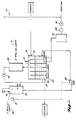
- FIG. 1 shows a system for removing volatile organic halogenated compounds from potable water.
- FIG. 2 shows a system for removing phenol and volatile organic halogenated compounds from waste-water produced following paint stripping.
- FIG. 3 shows an apparatus which was used to test the efficacy of the invention.
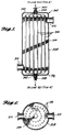
- FIG. 5 is a sectional view of the detoxification unit of FIG. 4 taken along the lines 5-5.
- a system 10 is shown suitable for purifying a water supply containing trichloroethylene in concentrations of from 15 to 40 parts per billion.
- the system 10 has a water influent port 12, typically admitting 0.90 to 1.35 litres/minute (20 to 30 gallons per minute), a reactor tank 14 with a series of baffles 16, and a water effluent port 18.
- the water contaminated with trichloroethylene flows into influent port 12 through baffles 16, and out through effluent port 18.
- Baffles 16 do not extend across the entire width of reactor tank 14, rather baffles 16 are disposed in the tank 14 such that the water flows around the sides of baffles 16; this baffle design prevents back-mixing of contaminated with decontaminated water and may also enhance ozone diffusion throughout the water in tank 14.
- the reactor tank 14 is equipped with thirty 40 Watt ultraviolet lamps 20 which provide electromagnetic radiation which includes some wavelengths from 185 nanometers to 254 nanometers.
- the portion of tank 14 near the influent port 12 has two tubular diffuser inlets 22 which admit an ozone/air mixture, produced by an ozone generator 24, into tank 14 and also aid in dispersing this mixture throughout the solution in tank 14.
- the ozone/air mixture in tank 14 acts in conjunction with the known decomposing action of the ultraviolet light produced by the lamps 20 and oxidizes most of the trichloroethylene in solution.
- a compressor 26 provides air to ozone generator 24 and a dryer 28 is positioned between compressor 26 and ozone generator 24 to ensure that the ozone generator's efficiency is not impeded by the presence of water in the air supply.
- Detoxification unit 29 is essentially a column of porous silica gel (quartz chips can also be used with the invention) wherein six 40 watt ultraviolet lamps 31 are positioned to irradiate the column.
- gases carrying volatile organic halogenated compounds such as the trichloroethylene
- detoxification unit 29 decomposes the trichloroethylene not decomposed by the action of the ultraviolet light and the ozone in reactor tank 14; near complete decomposition of the toxic trichloroethylene results.
- Degasser 32 Following treatment by detoxification unit 29, the resulting gases, which include some ozone, are pumped by a compressor 30 to a degasser 32.
- Degasser 32 has substantially detoxified water -- which has had the volatile organic halogenated compounds volatized from it and which has also been treated with ozone and ultraviolet light within reactor tank 14 -- flowing to it from the effluent end of tank 14.
- Degasser 32 employs six ultraviolet lamps 34 to provide ultraviolet light which decomposes residual ozone.
- An air inlet port 36 is also provided on degasser 32 to add make-up air to the system.
- a level gauge 37 is associated with degasser 32 and when degasser 32 becomes filled with detoxified water, a feed back system between level gauge 37 and a centrifugal pump 38 turns on pump 38 and water is pumped from the bottom of degasser 32 back to reactor tank 14. The water pumped back will contain any un-volatized or un-decomposed halogenated compounds; thus, these compounds are returned to the system for further treatment and oxidation.
- Air which has had the ozone removed therefrom by degasser 32, is returned to compressor 26 which mixes make-up air with the recycled air.
- Compressor 26 pumps the gaseous mixture to air dryer 28 which in turn feeds dried air to an ozone generator 24; thus, no gases or volatile organics are vented to the atmosphere.
- the detoxification unit 29 can also decompose other volatile organic halogenated compounds, for example: carbon tetrachloride; tetrachloroethylene; vinyl chloride; ethylene dibromide; methylene chloride, 1,1,1,-trichloroethane; chlorobenzene; hexachloroethane; 1,1-dichloroethane; 1,1,2-trichloroethane, 1,1,2,2-tetrachloroethane; bis(chloromethyl) ether; bis (2-chloroethyl) ether; 2-chloroethyl vinyl ether (mixed); chloroform; 1,2-dichlorobenzene; 1,3-dichlorobenzene; 1,4-dichlorobenzene; 1,1-dichloroethylene; 1,2-trans-dichloroethylene; 1,2-dich
- Waste water contaminated with up to 4,000 parts per million of methylene chloride and also contaminated with phenol is pumped by a pump 110 from a tank 112 at a rate of 0.15 to 0.18 litres/minutes (3 to 4 gallons per minute).
- the water passes through a heat exchanger 116 and is then preheated to about 75 to 80°C by a heater 118; thereafter it enters a reactor tank 114.
- Reactor tank 114 is equipped with a set of internal heaters 120 which maintain the reaction temperature of the waste water. Maintaining the reaction temperature enhances oxidation of phenol and also may serve to enhance the rate of methylene chloride vaporization and decomposition.
- Reactor tank 114 is provided with an impermeable wall 122 which divides tank 114 into first and second sections 124 and 126, respectively.
- First section 124 houses internal heaters 120 as well as four baffles 128.
- the baffles 128 are designed to extend only part-way across tank 114 in order to prevent back-mixing of the water. This design may also enhance dispersion of gases which enter tank 114 through a set of tubular diffusers 140.
- Tank 114 is also equipped with an air inlet 130 to provide make-up air to the system.
- Tank 114 can be provided with a levelling gauge 131 to indicate the water level in the tank.
- a compressor 132 pumps air, carrying methylene chloride volatized by the gases entering through tubular diffusers 140, from the top of tank 114 into a detoxification unit 134.
- Detoxification unit 134 is essentially the same as detoxification unit 29.
- Detoxification unit 134 is designed to. decompose the volatized methylene chloride and is essentially a porous bed of silica gel (or quartz chips) irradiated with eight 40 Watt ultraviolet lamps 135 which provide ultraviolet light.
- the ultraviolet light includes some wavelengths from 185 nano-m to 254 nano-m. Due to the similarity between detoxification unit 134 and detoxification unit 29, system 100 can decompose all the same volatile organic halogenated compounds which can be decomposed by system 10.
- paint stripping waste water typically contains traces of the following elements.
- ELEMENT CONCENTRATION (ppm) Chromium 51.0 Zinc 10.0 Copper 0.05 Nickel 0.06 Cadmium 0.02 Lead 0.2
- the detoxified water near wall 122 is pumped by a centrifugal pump 142 into second section 126 of tank 114. Also entering second section 126 through a set of tubular diffusers 144 is ozone produced by an ozone generator 146.
- the detoxified water and ozone are mixed in second section 126 of oxidize the intermediate aliphatic acids produced by the oxidation of phenol. Ozone then passes from the top of second section 126 into an ozone decomposer 152 which produces oxygen and releases it to the atmosphere.
- the detoxification unit 308, along with the other portions of system 306, can be used as the detoxification unit portion of either of systems 10 or 100.
- Detoxification unit 308 has a housing 328 with caps 330 and 332, respectively, affixed to the upper and lower ends of housing 328.
- Housing 328 provides a hermetic seal around a 6 to 16 mesh porous silica gel bed 334 (alternatively, a porous bed of quartz chips can be used) and also around a plurality of 40 watt low pressure, high intensity, ultraviolet lamps 336.
- Toxic gases flow through air supply port 310, through the silica gel bed 334, and out through exhaust port 312.
- lamps 336 irradiates silica gel bed 334 and acts to aid in decomposing any volatile organic halogenated compounds in the gases.
- Lamp leads 338 and 340 respectively positioned in mouths 342 and 344, supply power to the lamps 336 from the power lines 321 and 320.
- FIG. 6 a sectional view of detoxification unit 308 taken along the lines 6-6 is shown.
- FIG. 6 shows forty-eight lamps 336; a greater or a lesser number of lamps can be used in other embodiments of the invention.
- Tank 216 and bottles 218 contain aqueous solutions of the volatile organic halogenated compounds and air carrying these compounds was volatilized from either tank 216 or bottles 218.
- test apparatus 210 A variety of embodiments of test apparatus 210 were used. Valves A to H are shown to schematically indicate the different flow paths of the air carrying these compounds when this air passed through the different embodiments of test apparatus 210. Referring to Table 1, in the first, third and fifth group of experiments the air flow was "open", meaning that the air flowed along flow path 219 from the bottom of detoxification unit 212 to the scrubber bottles 214. Bottles 214 trap undecomposed organic halogenated compounds. In these groups of experiments no air flowed from unit 212 to either the tank 216 or to the bottles 218, this can be envisioned by closing valves A and B and opening valve H.
- the air flow was "cyclic", indicating that the air was pumped by compressor 225 along flow path 223 or 221 and was then returned to either of tank 216 or bottles 218. This can be envisioned by opening valves A or B and closing valve H.
- Detoxification unit 212 is essentially a hermetic cylindrical housing with an ultraviolet lamp 220 extending through the center thereof, and with a granular silica gel bed 222 surrounded by heating tape 224.
- Heating tape 224 which heats silica gel bed 222, was activated between runs and nitrogen gas was simultaneously passed through silica gel bed 222. Although this heating/nitrogen treatment temporarily improved the efficacy of the detoxification unit, good results were also obtained without this treatment.
- Valves C and F, and D and E are shown to schematically indicate that there were two further different embodiments of unit 212, one of which allowed air flow through the sides of unit 212 (indicated schematically by opening valves C and E) and one of which allowed air flow through the top and bottom of the unit 212 (indicated schematically by opening valves F and D).
- the embodiment of unit 212 actually used is immaterial to the experimental results and is therefore not indicated in Table 1.
- Valves I and J, and K and L are shown to indicate that water can be flowing through one of flow paths 229 and 231, or can be batched, as indicated in Table 1.
- the prototype detoxification unit employing silica gel irradiated with ultraviolet light and/or exposed to ozone, can be used in a wide variety of systems in modified forms to destroy a wide variety of volatile organic halogenated compounds. It is believed that any organic halogenated compound which can be decomposed by ultraviolet light and/or ozone and which can be volatized from aqueous solution, can be decomposed by the detoxification unit.
- Such volatile organic halogenated compounds include, but are not limited to: tetrachloroethylene; vinyl chloride; carbon tetrachloride; ethylene dibromide; methylene chloride, 1,1,1,-trichloroethane; chlorobenzene; hexachloroethane; 1,1-dichloroethane; 1,1,2-trichloroethane, 1,1,2,2-tetrachloroethane; chloroethane; bis(chloromethyl ether; bis (2-chloroethyl) ether; 2-chloroethyl vinyl ether (mixed); chloroform; 1,2-dichlorobenzene; 1,3-dichlorobenzene; 1,4-dichlorobenzene; 1,1-dichloroethylene; 1,2-transdichloroethylene; 1,2-dichloropropane; 1,2-dichloropropylene; bis (2-chloroisopropyl) ether; bis (2-chlor
- a slightly modified apparatus similar in function to a conventional counter-current air stripping tower, was fabricated.
- the modified apparatus (not shown) passed water downwardly through a column of aluminum chips and passed air upwardly through the column. The air then flowed to a 2.54 cm (one inch) diameter detoxification unit which had either a bed of silica gel or porous quartz chips irradiated by ultraviolet light, and was in all other respects the same as the 5.08 cm (two-inch) diameter detoxification unit 212 seen in FIG. 3.
- the ultraviolet light used when performing all these experiments contained a plurality of wavelengths, including some wavelengths between 185 nanometers to 254 nanometers.
- a set of unreported experiments was conducted to determine if the wavelengths of the ultraviolet light affected the rate of halogenated compound decomposition.
- ozone was added to a solution of organic halogenated compounds and the solution was irradiated with ultraviolet light.
- An aqueous solution of organic halogenated compounds was introduced into a reactor tank with one centrally located 40 watt ultraviolet lamp. Through the bottom of the tank was fed a mixture of ozone/oxygen, or ozone/air, or ozone/nitrogen.
- a 3.3 cm (1.3 inch) diameter embodiment of a detoxification unit similar to detoxification unit 212 as seen in Fig. 3 was used with the following modifications.
- the detoxification unit consisted of a glass cylindrical housing containing a column of granular silica gel with glass wool plugs at both ends to retain the silica gel in place, and silicone rubber stoppers at the top and bottom to seal the cylindrical housing. The stoppers were provided with gas inlet and outlet openings. The temperature of the silica gel bed was controlled by means of a heating tape 224 as seen in Fig.
- This test apparatus provided a means for testing a batch of TCE-containing solution. Additional volumes of TCE were introduced into the solution in the glass cylinder at selected time intervals to replenish the TCE in solution for additional test runs.
- the cylindrical housing included a 40 watt ultraviolet lamp 220 (74 cm long) extending through the center of the cylinder. For experiments using only ozone exposure, the ultraviolet lamp was omitted.
- the temperature on the tape was controlled by a Variac auto transformer type 3PN1010 (Staco Energy Products Co., Dayton, OH). A thermometer (VWR Scientific Inc.) was installed in the top of the cylinder with the bulb immersed in the silica gel column, and the glass tube was mounted vertically.
- the percent of TCE that passed through the detoxification unit was below one percent.
- the space velocity in this case was 920 reciprocal hours.
- the TCE was maintained at 350 ppb in water but the gas flow rate was increased to 6.3 L/M.
- test Run Nos. 8-16 TCE dosage was reduced from 350 ppb to 50 ppb. All the other parameters were kept constant.
- the volume of TCE that passed through the detoxification unit varied from 3% up to 80%.
- An increase in temperature of 5°C in test Run Nos. 17-20 did not have any significant effect on the removal of TCE in the system.
- Table 5 describes the testing that was done after the partial regeneration of the silica gel. Again, a starting concentration of 50 ppb of TCE was removed from the water solution. The air flow was kept at 6.3 L/M and the ozone input flow was maintained at .3 L/M. The temperature was raised to 50°C and, as shown in Table 5, the amount of TCE passing through the detoxification unit was below detectable limits up to test Run No. 30. After that, there was again a breakthrough of the TCE, and it was concluded that the silica gel was saturated. The silica gel was again partially regenerated with nitrogen at a rate of 1 L/M at 85°C for two hours.
- Table 6 shows the results of tests where the temperature was raised to 60°C. All the other variables were kept at the same levels as in Table 5. In the nineteen tests that were conducted in this series of runs, there was no breakthrough of TCE in the detoxification. It was concluded that a 60°C temperature was required in order to maintain an equilibrium and prevent breakthrough of the TCE through the same silica gel at the operating conditions shown in Table 6.
- TCE (ppb) Gas Flow Thru D-TOX (L/M) 2% O3/O2 Flow (L/M) Temp.
- test Run Nos. 57-60 the TCE in the water was increased to 700 ppb and all other conditions were maintained the same as in Table 6. Twenty two to 26% of the TCE passed through the same silica gel in this case.
- test Run Nos. 61-64 the temperature was raised to 70°C and resulted in a slight increase in the percent of TCE passing through the silica gel.
- test Run Nos. 65-70 the temperature was reduced to 60°C, and the ozone input flow was slightly increased to 0.5 L/M. These two changes again did not seem to have a significant effect on the removal of TCE through the silica gel.
- test Run Nos. 57-60 the TCE in the water was increased to 700 ppb and all other conditions were maintained the same as in Table 6. Twenty two to 26% of the TCE passed through the same silica gel in this case.
- test Run Nos. 61-64 the temperature was raised to 70°C and resulted in a slight increase in the percent of TCE passing through the silica
- Table 8 describes the substitution of 3-9 mesh silica gel for the previously used 6-16 mesh silica gel to determine the effect of mesh size on the adsorption of TCE.
- the weight of the 3-8 mesh silica gel was 147 grams, which was identical to the 6-16 mesh silica gel that was used in the cylinder.
- the coarser silica gel was packed into a 2" NPT stainless steel pipe.
- the apparent volume for the coarser silica gel was 190 cc, whereas the 6-16 mesh was 150 ml. All the tests in Table 8 removed 700 ppb of TCE from the water. Also held constant was the ozone flow rate at 0.3 L/M and the temperature at 60°C.
- the space velocity through the silica gel was varied from 1042 reciprocal hours to 3253 reciprocal hours. Comparing test Run Nos. 99-103 in Table 8 with test Run Nos. 57-60 in Table 7, the coarser mesh appears to reduce the TCE passing through the silica gel to approximately 1% less than when using the finer mesh silica gel. The same silica gel was used throughout this series of tests.
- Ultraviolet light alone removes 80% or better of the TCE with space velocities in the 2400 reciprocal hour range.
- the addition of ozone with ultraviolet light may enhance the oxidation of the TCE.
- the basic organic halogenated compound detoxification unit (using a bed of either silica gel or quartz chips and irradiation with ultraviolet light and/or exposure to ozone) can also be used in a wide variety of industrial applications other than those previously described. These halogenated compounds are used and/or produced in dry cleaning, in incinerators which produce these compounds as offgases, in many chemical processes, following chemical spills, and in chemical storage tanks; the unit could be used for detoxification in any of these sytems. It is also hypothesized that a smaller-mesh silica gel bed could be used as a purification system for water which contains bacteria. It is known that ultraviolet light kills bacteria and it is believed that passing bacteria contaminated water through the detoxification unit would increase the rate of bacterial destruction.
Claims (17)
- Vorrichtung zum Zersetzen organischer Verbindungen, die in Gasen und wäßrigen Lösungen enthalten sind, umfassend:a) einen Reaktortank, um eine verunreinigte wäßrige Lösung gleichzeitig Ozon und ultravioletter Strahlung auszusetzen, um organische Verbindungen in der Lösung zu oxidieren und die organischen Verbindungen aus der Lösung verdampfen zu lassen, wobei der Reaktortank mindestens eine Zuflußöffnung für einströmende Lösung und mindestens eine Ausflußöffnung für ausströmende Lösung aufweist, und wobei der Reaktortank mindestens ein Gasdiffusionsrohr aufweist, das proximal zu der Zuflußöffnung für die Einleitung von Ozon in die verunreinigte Lösung in dem Tank liegt, und wobei der Reaktortank ein Hilfsmittel zur Ultraviolettbestrahlung enthält;b) ein an mindestens ein Gasdiffusionsrohr gekoppeltes Ozonbildungshilfsmittel zur Erzeugung von Ozon aus Luft, um ein Ozon-Luft-Gemisch herzustellen, und um das Ozon-Luft-Gemisch in den Reaktortank zur Umsetzung mit der verunreinigten Lösung einzuleiten, undc) eine Entgiftungseinheit, die an den Reaktortank gekoppelt ist, um die verdampften organischen halogenierten Verbindungen zu zersetzen, die in den Gasen enthalten sind, wobei die Entgiftungseinheit eine Mehrzahl von Bestrahlungshilfsmitteln zum Bestrahlen der verdampften organischen Verbindungen und eine poröse Adsorptionsmittelschicht zur Adsorption von Ozon und organischen Verbindungen aufweist, die so angeordnet ist, daß die poröse Adsorptionsmittelschicht diese Bestrahlungshilfsmittel umgibt und sich in einem Abstand befindet, der zur Förderung der Reduktion der verdampften organischen halogenierten Verbindungen in den Gasen wirksam ist.
- Vorrichtung nach Anspruch 1, wobei die Bestrahlungshilfsmittel in Quarzgehäusen in der Entgiftungseinheit eingeschlossen sind.
- Vorrichtung nach Anspruch 1 oder 2, wobei der Reaktortank darüber hinaus eine Mehrzahl von Kammern umfaßt, die von einer Mehrzahl von longitudinalen Prallplatten gebildet werden, um den Fluß der in die Kammern einströmenden Lösung von der Zuflußöffnung zu der Ausflußöffnung des Reaktortanks zu erleichtern, wobei die Prallplatten parallel zueinander angeordnet sind und eine Länge aufweisen, die weniger als die Breite des Reaktortanks beträgt, um den Durchfluß der Lösung zwischen den Kanälen zu gestatten, die von den Prallplatten gebildet werden.
- Vorrichtung nach einem der vorhergehenden Ansprüche, bei der die Bestrahlungshilfsmittel eine Mehrzahl ultravioletter Lampen umfaßt, wobei die Lampen, bezogen auf die Längsanordung der Prallplatten, vertikal in den Kammern des Reaktortanks angebracht sind.
- Vorrichtung nach einem der vorhergehenden Ansprüche, wobei die poröse Adsorptionsmittelschicht Silikagel enthält.
- Vorrichtung nach einem der vorhergehenden Ansprüche, wobei die Entgiftungseinheit Hilfsmittel zum Erwärmen der porösen Adsorptionsmittelschicht umfaßt.
- Vorrichtung zum Zersetzen von in Gasen enthaltenen flüchtigen organischen halogenierten Verbindungen, umfassend:a) ein Gehäuse mit einer Gaszufuhröffnung, einer Abgasöffnung und einem Gasströmungsweg zwischen der Gaszufuhröffnung und der Abgasöffnung,b) eine poröse Adsorptionsmittelschicht, die sich in dem Gasströmungsweg befindet, wobei die poröse Adsorptionsmittelschicht in der Lage ist, Ozon und flüchtige organische halogenierte Verbindungen aus dem gasförmigen Zustand zu adsorbieren, undc) Hilfsmittel zum Bestrahlen der porösen Adsorptionsmittelschicht mit ultraviolettem Licht, wobei die poröse Adsorptionsmittelschicht die Bestrahlungshilfsmittel in einem Abstand umgibt, der zur Förderung der Reduktion der flüchtigen organischen Verbindungen in den Gasen wirksam ist.
- Vorrichtung nach Anspruch 7, die darüber hinaus Hilfsmittel enthält, um die poröse Adsorptionsmittelschicht dem Ozon auszusetzen.
- Vorrichtung zum Zersetzen von in Gasen enthaltenen flüchtigen organischen halogenierten Verbindungen, umfassend:a) ein Gehäuse mit einer Gaszufuhröffnung, einer Abgasöffnung und einem Gasströmungsweg zwischen der Gaszufuhröffnung und der Abgasöffnung,b) eine poröse Adsorptionsmittelschicht, die sich in dem Gasströmungsweg befindet, wobei die poröse Adsorptionsmittelschicht in der Lage ist, Ozon und flüchtige organische halogenierte Verbindungen aus dem Gaszustand zu adsorbieren, undc) Hilfsmittel, um die poröse Adsorptionsmittelschicht Ozon auszusetzen und die Reduktion der flüchtigen organischen Verbindungen in den Gasen zu fördern.
- Verfahren zum Zersetzen flüchtiger organischer halogenierter Verbindungen in Gasen, umfassend das Strömen von Gas, das die flüchtigen organischen Verbindungen trägt, durch eine poröse Adsorptionsmittelschicht aus Silikagel, während die poröse Schicht mit ultraviolettem Licht bestrahlt wird und/oder die poröse Adsorptionsmittelschicht für eine Zeitdauer, die wirksam ist, um die flüchtigen organischen halogenierten Verbindungen in den Gasen zu zersetzen, Ozon ausgesetzt wird.
- Verfahren nach Anspruch 10, wobei das Ozon dem Gas, das die flüchtigen organischen Verbindungen enthält, zugesetzt wird, bevor das Gas durch die poröse Adsorptionsmittelschicht aus Silikagel strömt.
- Verfahren nach Anspruch 10 oder 11, worin die Temperatur der porösen Schicht auf annähernd 50° - 70°C geregelt wird, um die Zersetzung der flüchtigen organischen halogenierten Verbindungen zu fördern.
- Verfahren nach einem der Ansprüche 10 - 12, worin die Gase trockene, feuchte oder wassergesättigte Gase sind.
- Verfahren nach einem der Ansprüche 10 - 13, das in der Vorrichtung nach einem der Ansprüche 1 - 9 durchgeführt wird.
- Verfahren zum Zersetzen flüchtiger, organischer halogenierter Verbindungen, die in wäßrigen Lösungen enthalten sind, umfassend:a) Verdampfen der flüchtigen organischen halogenierten Verbindungen aus einer verunreinigten wäßrigen Lösung in einen gasförmigen Träger, indem der gasförmige Träger durch die wäßrige Lösung geleitet wird, undb) Leiten des gasförmigen Trägers durch eine poröse Adsorptionsmittelschicht aus Silikagel, während die poröse Adsorptionsmittelschicht ultraviolettem Licht und/oder Ozon ausgesetzt wird, um die flüchtigen organischen halogenierten Verbindungen in den Gasen merklich zu zersetzen.
- Verfahren nach Anspruch 15, worin die verunreinigte wäßrige Lösung kontinuierlich fließt und das darüber hinaus das Wiederverwerten des gasförmigen Trägers umfaßt, um weiterhin organische halogenierte Verbindungen zu entfernen, indem der gasförmige Träger in die kontinuierlich fließende wäßrige Lösung zurückgeführt wird, um die flüchtigen halogenierten Verbindungen zu verdampfen, und Leiten des rückgeführten gasförmigen Trägers durch die poröse Adsorptionsmittelschicht, während die poröse Adsorptionsmittelschicht ultraviolettem Licht und/oder Ozon ausgesetzt wird.
- Verfahren nach Anspruch 15 oder 16, das in der Vorrichtung nach einem der Ansprüche 1 - 6 durchgeführt wird.
Priority Applications (1)
| Application Number | Priority Date | Filing Date | Title |
|---|---|---|---|
| AT88309759T ATE86517T1 (de) | 1988-09-30 | 1988-10-18 | Zersetzung von fluechtigen, halogenierten organischen verbindungen in gasen und waessrigen loesungen. |
Applications Claiming Priority (2)
| Application Number | Priority Date | Filing Date | Title |
|---|---|---|---|
| US250842 | 1988-09-30 | ||
| US07/250,842 US4941957A (en) | 1986-10-22 | 1988-09-30 | Decomposition of volatile ogranic halogenated compounds contained in gases and aqueous solutions |
Publications (3)
| Publication Number | Publication Date |
|---|---|
| EP0360941A2 EP0360941A2 (de) | 1990-04-04 |
| EP0360941A3 EP0360941A3 (en) | 1990-12-19 |
| EP0360941B1 true EP0360941B1 (de) | 1993-03-10 |
Family
ID=22949383
Family Applications (1)
| Application Number | Title | Priority Date | Filing Date |
|---|---|---|---|
| EP88309759A Expired - Lifetime EP0360941B1 (de) | 1988-09-30 | 1988-10-18 | Zersetzung von flüchtigen, halogenierten organischen Verbindungen in Gasen und wässrigen Lösungen |
Country Status (5)
| Country | Link |
|---|---|
| US (1) | US4941957A (de) |
| EP (1) | EP0360941B1 (de) |
| AT (1) | ATE86517T1 (de) |
| CA (1) | CA1329378C (de) |
| DE (1) | DE3879205D1 (de) |
Families Citing this family (50)
| Publication number | Priority date | Publication date | Assignee | Title |
|---|---|---|---|---|
| IL94285A0 (en) * | 1990-05-04 | 1991-03-10 | Spectronix Ltd | Method and apparatus for providing ecological protection with respect to equipment using a halogenated hydrocarbon |
| US5190626A (en) * | 1990-12-13 | 1993-03-02 | Allied-Signal Inc. | Process for removing vinylidene chloride and other unsaturated compounds from 1,1-dichloro-1-fluoroethane |
| US5219534A (en) * | 1991-04-26 | 1993-06-15 | Reynolds Warren D | Process and apparatus for decontaminating air |
| DE69224627T2 (de) * | 1991-05-30 | 1998-09-17 | Roger Carson Later | Verfahren und vorrichtung für die entgiftung von erdboden |
| US5191261A (en) * | 1991-06-11 | 1993-03-02 | Purus, Inc. | Switching power supply for high-voltage flash lamps |
| US5397552A (en) * | 1992-02-27 | 1995-03-14 | Process Technologies, Inc. | Method and apparatus for use in photochemically oxidizing gaseous organic compounds |
| US5260036A (en) * | 1992-02-27 | 1993-11-09 | Process Technologies, Inc. | Method and apparatus for use in photochemically oxidizing gaseous halogenated organic compounds |
| IT1259654B (it) * | 1992-05-14 | 1996-03-25 | Renzacci Spa | Procedimento ed apparecchiatura per l'eliminazione dei residui di solvente clorurato dalle acque di contatto risultanti dalla fase di asciugatura nelle apparecchiature per la pulitura a secco degli indumenti |
| DE4221774A1 (de) * | 1992-07-02 | 1994-01-05 | Solvay Umweltchemie Gmbh | Verfahren zur Begasung und Entkeimung und Vorrichtung zur simultanen Durchführung |
| DE4238324A1 (de) * | 1992-11-13 | 1994-05-19 | Abb Research Ltd | Verfahren und Einrichtung zur Entgiftung von schadstoffhaltigen Gasen |
| GB9318830D0 (en) * | 1993-09-10 | 1993-10-27 | Colt Int Ltd | Method and apparatus for removing odours from a gas system |
| US6306296B1 (en) | 1995-05-05 | 2001-10-23 | William B. Kerfoot | Groundwater and soil remediation with microporous diffusion apparatus |
| US5855775A (en) | 1995-05-05 | 1999-01-05 | Kerfoot; William B. | Microporous diffusion apparatus |
| USRE43350E1 (en) | 1995-05-05 | 2012-05-08 | Think Village-Kerfoot, Llc | Microporous diffusion apparatus |
| US6312605B1 (en) | 1995-05-05 | 2001-11-06 | William B. Kerfoot | Gas-gas-water treatment for groundwater and soil remediation |
| FR2735213B1 (fr) | 1995-06-12 | 1997-07-11 | Kodak Pathe | Procede et dispositif de destruction par incineration de gaz de reaction |
| US5601184A (en) * | 1995-09-29 | 1997-02-11 | Process Technologies, Inc. | Method and apparatus for use in photochemically oxidizing gaseous volatile or semi-volatile organic compounds |
| DE19546061C5 (de) | 1995-12-09 | 2008-02-28 | Schröder, Werner | Verfahren zur Abluftreinigung |
| US5861123A (en) * | 1996-04-26 | 1999-01-19 | Ceco Filters, Inc. | Ultraviolet light irradiated ebullating mass transfer system |
| US5955037A (en) | 1996-12-31 | 1999-09-21 | Atmi Ecosys Corporation | Effluent gas stream treatment system having utility for oxidation treatment of semiconductor manufacturing effluent gases |
| US6322756B1 (en) * | 1996-12-31 | 2001-11-27 | Advanced Technology And Materials, Inc. | Effluent gas stream treatment system having utility for oxidation treatment of semiconductor manufacturing effluent gases |
| US6277347B1 (en) * | 1997-02-24 | 2001-08-21 | Applied Materials, Inc. | Use of ozone in process effluent abatement |
| US5986160A (en) * | 1998-03-06 | 1999-11-16 | University Of Kentucky Research Foundation | Method of destroying hazardous organic compounds |
| KR100358624B1 (ko) * | 1998-06-22 | 2002-10-25 | 미츠비시 쥬고교 가부시키가이샤 | 오염 물질을 함유하는 오염 유체의 처리 방법 |
| US6436285B1 (en) * | 1999-12-22 | 2002-08-20 | William B. Kerfoot | Laminated microporous diffuser |
| CA2338668C (en) * | 2000-02-29 | 2005-02-15 | Canon Kabushiki Kaisha | Polluted soil remediation apparatus, polluted soil remediation method, pollutant degrading apparatus and pollutant degrading method |
| US6582611B1 (en) | 2000-07-06 | 2003-06-24 | William B. Kerfoot | Groundwater and subsurface remediation |
| US8557110B2 (en) * | 2000-07-06 | 2013-10-15 | Thinkvillage-Kerfoot, Llc | Groundwater and subsurface remediation |
| CN100551467C (zh) * | 2002-03-28 | 2009-10-21 | 兴研株式会社 | 有机化合物的分解装置 |
| US8302939B2 (en) * | 2003-02-12 | 2012-11-06 | Thinkvillage-Kerfoot, Llc | Soil and water remediation system and method |
| US7442313B2 (en) * | 2003-08-27 | 2008-10-28 | Thinkvillage-Kerfoot, Llc | Environmental remediation method and system |
| US7666316B2 (en) | 2004-07-20 | 2010-02-23 | Thinkvillage-Kerfoot, Llc | Permanganate-coated ozone for groundwater and soil treatment with in-situ oxidation |
| US6913251B2 (en) | 2003-02-12 | 2005-07-05 | William B. Kerfoot | Deep well sparging |
| US7547388B2 (en) * | 2004-07-20 | 2009-06-16 | Think Village-Kerfoot, Llc | Superoxidant poiser for groundwater and soil treatment with in-situ oxidation-reduction and acidity-basicity adjustment |
| US7651611B2 (en) * | 2006-07-12 | 2010-01-26 | Thinkvillage-Kerfoot, Llc | Directional microporous diffuser and directional sparging |
| US8771507B2 (en) | 2003-12-24 | 2014-07-08 | Thinkvillage-Kerfoot, Llc | Directional microporous diffuser and directional sparging |
| US7569140B2 (en) * | 2005-11-10 | 2009-08-04 | Thinkvillage-Kerfoot, Llc | Directional spargewell system |
| US7621696B2 (en) * | 2006-07-12 | 2009-11-24 | Thinkvillage-Kerfoot, Llc | Directional microporous diffuser and directional sparging |
| US7401767B2 (en) * | 2003-12-24 | 2008-07-22 | Kerfoot William B | Directional microporous diffuser and directional sparging |
| US7736599B2 (en) | 2004-11-12 | 2010-06-15 | Applied Materials, Inc. | Reactor design to reduce particle deposition during process abatement |
| US8419858B1 (en) | 2004-12-08 | 2013-04-16 | Haydock Intellectual Properties, LLC | Method and system for removing organic compouds in a closed loop system |
| WO2006131148A1 (en) * | 2005-06-07 | 2006-12-14 | Roberto Giampieri | Apparatus for the treatment of objects to be decontaminated by exposure to a flow of ozone |
| DE102005035951A1 (de) * | 2005-07-28 | 2007-02-01 | Nonnenmacher, Klaus, Dipl.-Ing. Prof. | Verfahren und Vorrichtung zur Reinigung und/oder Sterilisierung von Luft mittels Ozon |
| DE102005049923B4 (de) * | 2005-10-17 | 2017-12-14 | KMU LOFT Cleanwater GmbH | Verfahren und Anordnung zum Reinigen von industriell verunreinigtem Abwasser/Prozesswasser mittels einer Destillationsanlage |
| EP1954926A2 (de) | 2005-10-31 | 2008-08-13 | Applied Materials, Inc. | Prozessunterdrückungsreaktor |
| US7820137B2 (en) * | 2006-08-04 | 2010-10-26 | Enerdel, Inc. | Lithium titanate and method of forming the same |
| EP2164812A4 (de) * | 2007-06-22 | 2011-08-03 | Carrier Corp | Reinigung eines fluids unter verwendung von ozon mit einem adsorptionsmittel und/oder einem partikelfilter |
| US9694401B2 (en) | 2013-03-04 | 2017-07-04 | Kerfoot Technologies, Inc. | Method and apparatus for treating perfluoroalkyl compounds |
| CZ305690B6 (cs) * | 2014-11-19 | 2016-02-03 | Vysoká škola chemicko- technologická v Praze | Zařízení pro čištění plynů obsahujících těkavé organické sloučeniny |
| CN111760452A (zh) * | 2020-06-29 | 2020-10-13 | 盐城工学院 | 一种光催化臭氧协同催化降解挥发性有机气体性能测试的实验装置及其运行工艺 |
Family Cites Families (28)
| Publication number | Priority date | Publication date | Assignee | Title |
|---|---|---|---|---|
| DE281772C (de) * | ||||
| US1969655A (en) * | 1923-09-27 | 1934-08-07 | Gen Electric Vapor Lamp Co | Reaction chamber |
| US2588716A (en) * | 1947-09-30 | 1952-03-11 | Allied Lab Inc | Process and apparatus for the irradiation of liquids |
| US3336099A (en) * | 1963-01-23 | 1967-08-15 | Czulak Joseph | Apparatus for the sanitization of liquids with especial application to water storages and swimming pools |
| US3732163A (en) * | 1971-11-03 | 1973-05-08 | Gen Electric | Process and apparatus for the ozone treatment of a liquid material |
| DE2300273C3 (de) * | 1972-01-07 | 1982-05-06 | Toray Industries, Inc., Tokyo | Vorrichtung für Abwasserreinigung |
| US3766060A (en) * | 1972-07-12 | 1973-10-16 | Vaponics | Rinse water purification |
| DE2462995C2 (de) * | 1974-02-23 | 1984-10-11 | C.F. Spiess & Sohn GmbH & Co, 6719 Kleinkarlbach | Verfahren zum Reinigen von verschmutztem Grund- und Trinkwasser |
| US3920547A (en) * | 1974-05-06 | 1975-11-18 | Houston Research Inc | Method of destroying cyanides |
| US3951770A (en) * | 1974-07-05 | 1976-04-20 | Texaco Inc. | Hydrocarbon conversion |
| US3980755A (en) * | 1975-02-19 | 1976-09-14 | Rohm And Haas Company | System for removing chloromethyl ether and bis-chloromethyl ether from air contaminated therewith |
| US4045316A (en) * | 1975-05-27 | 1977-08-30 | Shintech Incorporated | Photochemical process for decontaminating gaseous or vaporous streams |
| US4045538A (en) * | 1975-11-28 | 1977-08-30 | Ppg Industries, Inc. | Catalytic oxidation of vinyl chloride |
| US4210503A (en) * | 1975-12-31 | 1980-07-01 | Exxon Research & Engineering Co. | Emission control method and system |
| US4039623A (en) * | 1976-08-16 | 1977-08-02 | Ppg Industries, Inc. | Catalytic oxidation of C2-C4 halogenated hydrocarbons |
| US4179616A (en) * | 1978-02-21 | 1979-12-18 | Thetford Corporation | Apparatus for sanitizing liquids with ultra-violet radiation and ozone |
| US4144152A (en) * | 1978-03-27 | 1979-03-13 | Atlantic Research Corporation | Dehalogenation of halogenated compounds |
| DE2854462C2 (de) * | 1978-12-16 | 1986-10-16 | Gesellschaft für Strahlen- und Umweltforschung mbH, 8000 München | Vorrichtung zur Bestimmung der Photomineralisierbarkeit adsorbierter chemischer Verbindungen |
| JPS57183306A (en) * | 1981-04-30 | 1982-11-11 | Mitsubishi Electric Corp | Ozonizer |
| JPS5939386A (ja) * | 1982-08-27 | 1984-03-03 | Fuji Electric Corp Res & Dev Ltd | 水道水中の有機ハロゲン化合物除去方法 |
| JPS59150589A (ja) * | 1983-02-17 | 1984-08-28 | Raizaa Kogyo Kk | 用廃水の浄化方法とその装置 |
| JPS60114393A (ja) * | 1983-11-22 | 1985-06-20 | Samuson Eng Kk | 廃水処理装置 |
| US4780287A (en) * | 1984-07-03 | 1988-10-25 | Ultrox International | Decomposition of volatile organic halogenated compounds contained in gases |
| JPS6128445A (ja) * | 1984-07-20 | 1986-02-08 | Oak Seisakusho:Kk | 紫外線照射装置 |
| JPS6274484A (ja) * | 1985-09-30 | 1987-04-06 | Toshiba Corp | 液体浄化装置 |
| JPS62163730A (ja) * | 1986-01-13 | 1987-07-20 | Ebara Infilco Co Ltd | 排ガス処理方法 |
| JPS62191025A (ja) * | 1986-02-14 | 1987-08-21 | Nec Corp | 排ガスの処理方法 |
| US4863687A (en) * | 1986-09-26 | 1989-09-05 | Solarchem Enterprises Inc. | Method for removing malodorous or toxic gases from an air stream |
-
1988
- 1988-09-30 US US07/250,842 patent/US4941957A/en not_active Expired - Fee Related
- 1988-10-18 DE DE8888309759T patent/DE3879205D1/de not_active Expired - Lifetime
- 1988-10-18 AT AT88309759T patent/ATE86517T1/de not_active IP Right Cessation
- 1988-10-18 EP EP88309759A patent/EP0360941B1/de not_active Expired - Lifetime
- 1988-10-19 CA CA000580669A patent/CA1329378C/en not_active Expired - Fee Related
Also Published As
| Publication number | Publication date |
|---|---|
| EP0360941A3 (en) | 1990-12-19 |
| CA1329378C (en) | 1994-05-10 |
| DE3879205D1 (de) | 1993-04-15 |
| US4941957A (en) | 1990-07-17 |
| ATE86517T1 (de) | 1993-03-15 |
| EP0360941A2 (de) | 1990-04-04 |
Similar Documents
| Publication | Publication Date | Title |
|---|---|---|
| EP0360941B1 (de) | Zersetzung von flüchtigen, halogenierten organischen Verbindungen in Gasen und wässrigen Lösungen | |
| US4780287A (en) | Decomposition of volatile organic halogenated compounds contained in gases | |
| US4966665A (en) | Method for photochemical decomposition of volatile organic chlorine compound in vent gas | |
| CA2057874C (en) | Process and apparatus for the purification of contaminated water by activated ozone | |
| CA2350697C (en) | Apparatus for treating gas containing substance to be decomposed and method of treating its gas | |
| US5505856A (en) | Process for the purification of contaminated water by activated ozone | |
| KR20010023858A (ko) | 오염된 매질의 광촉매에 의한 처리 시스템 및 처리 방법 | |
| JP3293181B2 (ja) | 揮発性有機ハロゲン化合物含有ガスの気相分解処理方法 | |
| KR100502946B1 (ko) | 피분해 물질의 처리방법 및 그 장치 | |
| JP2813354B2 (ja) | 気体および水溶液中に含有される揮発性有機ハロゲン化化合物の分解 | |
| EP0242941B1 (de) | Verfahren und Vorrichtung zum Desodorisieren von Luft | |
| JPH08243351A (ja) | 有機塩素化合物の分解方法 | |
| JP3384464B2 (ja) | 揮発性有機塩素化合物の処理方法 | |
| US7144556B2 (en) | Method and apparatus for decomposition of substance contained in gas | |
| KR100478803B1 (ko) | 공기 정화처리방법 및 그 장치 | |
| JP2548665B2 (ja) | 吸着処理方法 | |
| KR200250579Y1 (ko) | 광촉매 반응과 활성탄 기능을 이용한 정화장치 | |
| KR100372535B1 (ko) | 휘발성 기체 유기화합물 처리장치 및 방법 | |
| JP2006247580A (ja) | 吸着剤の再生方法および塩素光分解性物質含有流体の浄化装置 | |
| JP3360353B2 (ja) | 揮発性有機ハロゲン化合物の処理方法 | |
| JP2001259664A (ja) | 汚染水および汚染ガスの浄化方法および装置 | |
| JPH07124443A (ja) | 揮発性有機ハロゲン化合物含有ガスの処理方法 | |
| JPH05329330A (ja) | 揮発性有機ハロゲン化合物の処理方法 | |
| JP3611278B2 (ja) | 汚染成分含有水の処理方法 | |
| JP2005103520A (ja) | 汚染物質の分解方法、それに用いる装置 |
Legal Events
| Date | Code | Title | Description |
|---|---|---|---|
| PUAI | Public reference made under article 153(3) epc to a published international application that has entered the european phase |
Free format text: ORIGINAL CODE: 0009012 |
|
| AK | Designated contracting states |
Kind code of ref document: A2 Designated state(s): AT BE CH DE ES FR GB GR IT LI LU NL SE |
|
| PUAL | Search report despatched |
Free format text: ORIGINAL CODE: 0009013 |
|
| AK | Designated contracting states |
Kind code of ref document: A3 Designated state(s): AT BE CH DE ES FR GB GR IT LI LU NL SE |
|
| 17P | Request for examination filed |
Effective date: 19910619 |
|
| 17Q | First examination report despatched |
Effective date: 19910910 |
|
| GRAA | (expected) grant |
Free format text: ORIGINAL CODE: 0009210 |
|
| AK | Designated contracting states |
Kind code of ref document: B1 Designated state(s): AT BE CH DE ES FR GB GR IT LI LU NL SE |
|
| PG25 | Lapsed in a contracting state [announced via postgrant information from national office to epo] |
Ref country code: IT Free format text: LAPSE BECAUSE OF FAILURE TO SUBMIT A TRANSLATION OF THE DESCRIPTION OR TO PAY THE FEE WITHIN THE PRE;WARNING: LAPSES OF ITALIAN PATENTS WITH EFFECTIVE DATE BEFORE 2007 MAY HAVE OCCURRED AT ANY TIME BEFORE 2007. THE CORRECT EFFECTIVE DATE MAY BE DIFFERENT FROM THE ONE RECORDED.SCRIBED TIME-LIMIT Effective date: 19930310 Ref country code: ES Free format text: THE PATENT HAS BEEN ANNULLED BY A DECISION OF A NATIONAL AUTHORITY Effective date: 19930310 Ref country code: GR Free format text: LAPSE BECAUSE OF FAILURE TO SUBMIT A TRANSLATION OF THE DESCRIPTION OR TO PAY THE FEE WITHIN THE PRESCRIBED TIME-LIMIT Effective date: 19930310 Ref country code: NL Effective date: 19930310 Ref country code: SE Effective date: 19930310 Ref country code: AT Effective date: 19930310 Ref country code: CH Effective date: 19930310 Ref country code: LI Effective date: 19930310 Ref country code: BE Effective date: 19930310 Ref country code: FR Effective date: 19930310 Ref country code: DE Effective date: 19930310 |
|
| REF | Corresponds to: |
Ref document number: 86517 Country of ref document: AT Date of ref document: 19930315 Kind code of ref document: T |
|
| REF | Corresponds to: |
Ref document number: 3879205 Country of ref document: DE Date of ref document: 19930415 |
|
| REG | Reference to a national code |
Ref country code: CH Ref legal event code: PL |
|
| EN | Fr: translation not filed | ||
| NLV1 | Nl: lapsed or annulled due to failure to fulfill the requirements of art. 29p and 29m of the patents act | ||
| PG25 | Lapsed in a contracting state [announced via postgrant information from national office to epo] |
Ref country code: LU Free format text: LAPSE BECAUSE OF NON-PAYMENT OF DUE FEES Effective date: 19931031 |
|
| PLBE | No opposition filed within time limit |
Free format text: ORIGINAL CODE: 0009261 |
|
| STAA | Information on the status of an ep patent application or granted ep patent |
Free format text: STATUS: NO OPPOSITION FILED WITHIN TIME LIMIT |
|
| 26N | No opposition filed | ||
| REG | Reference to a national code |
Ref country code: GB Ref legal event code: 732E |
|
| PGFP | Annual fee paid to national office [announced via postgrant information from national office to epo] |
Ref country code: GB Payment date: 19951009 Year of fee payment: 8 |
|
| PG25 | Lapsed in a contracting state [announced via postgrant information from national office to epo] |
Ref country code: GB Effective date: 19961018 |
|
| REG | Reference to a national code |
Ref country code: GB Ref legal event code: 732E |
|
| GBPC | Gb: european patent ceased through non-payment of renewal fee |
Effective date: 19961018 |