EP0359910A2 - Agencement de carrosserie pour un véhicule à moteur ou remorque - Google Patents
Agencement de carrosserie pour un véhicule à moteur ou remorque Download PDFInfo
- Publication number
- EP0359910A2 EP0359910A2 EP89110552A EP89110552A EP0359910A2 EP 0359910 A2 EP0359910 A2 EP 0359910A2 EP 89110552 A EP89110552 A EP 89110552A EP 89110552 A EP89110552 A EP 89110552A EP 0359910 A2 EP0359910 A2 EP 0359910A2
- Authority
- EP
- European Patent Office
- Prior art keywords
- chain
- cables
- body arrangement
- wings
- attached
- Prior art date
- Legal status (The legal status is an assumption and is not a legal conclusion. Google has not performed a legal analysis and makes no representation as to the accuracy of the status listed.)
- Withdrawn
Links
Images


Classifications
-
- B—PERFORMING OPERATIONS; TRANSPORTING
- B60—VEHICLES IN GENERAL
- B60P—VEHICLES ADAPTED FOR LOAD TRANSPORTATION OR TO TRANSPORT, TO CARRY, OR TO COMPRISE SPECIAL LOADS OR OBJECTS
- B60P3/00—Vehicles adapted to transport, to carry or to comprise special loads or objects
- B60P3/32—Vehicles adapted to transport, to carry or to comprise special loads or objects comprising living accommodation for people, e.g. caravans, camping, or like vehicles
- B60P3/34—Vehicles adapted to transport, to carry or to comprise special loads or objects comprising living accommodation for people, e.g. caravans, camping, or like vehicles the living accommodation being expansible, collapsible or capable of rearrangement
-
- B—PERFORMING OPERATIONS; TRANSPORTING
- B62—LAND VEHICLES FOR TRAVELLING OTHERWISE THAN ON RAILS
- B62D—MOTOR VEHICLES; TRAILERS
- B62D33/00—Superstructures for load-carrying vehicles
- B62D33/08—Superstructures for load-carrying vehicles comprising adjustable means
Definitions
- the invention relates to a body assembly for a motor vehicle or a trailer, such as. B. for a truck, a van, a semi-trailer, a car, a container or the like, consisting of a substantially rectangular structure with two side walls, two end walls, one of which can consist of two doors, and a roof.
- US-A-2 879 103 describes a motor vehicle in which the rear structure of the body can be raised and lowered by means of a telescopic linkage in order to reduce the volume of the structure during the journey
- US-A-3 061 358 also describes a motor vehicle with a body structure, the upper part of which can be raised and lowered, for which purpose racks and gears are essentially used.
- DE-A-31 50 707 describes a device for adjusting the height of vehicle bodies, in which adjustment supports are actuated by means of gas springs, an actuation device also being present, which consists of a cable winch with pulling cables and the pulling force of which adjusters against the action of the gas springs moved down.
- the present invention has for its object to remedy the disadvantages of the aforementioned body arrangements and to improve and simplify the design of the actuating device of the upper, raised and lowerable body part, wherein the friction between the moving parts during loading movement is reduced without the tightness is guaranteed in the respective final resting state, even in the presence of rear doors.
- a body assembly for a motor vehicle or a trailer such as. B. for a truck, a van, a semi-trailer, a car, a container or the like, consisting of a substantially rectangular structure with two side walls, two end walls, one of which can consist of two doors, and a roof, wherein the transport or loading space enclosing or determining structure in the unloaded or partially loaded state of the vehicle to reduce its height is formed horizontally and in two parts and box-shaped in such a way that the upper part is lowered telescopically above or into the lower part by means of a lifting device consisting of cables - And can be raised, which is characterized in that preferably in the lower part of the structure for raising and lowering the upper part a motor with a gear is arranged, which drives a chain in two directions via a gear, the ends of the chain with Cables are connected to the upper part via pulleys the ceiling and the lower edges are connected.
- an electric motor acts on a tensioned chain running along an end wall on the floor.
- the drive of the motor is designed so that the length of the chain can be moved in one direction and in the other.
- the four cables are attached, which run over deflection rollers to the lower corners of the upper part, where they are attached.
- four cables are also provided, which over Guide pulleys to the upper edges of the upper part.
- two doors of the rear end wall of the structure are divided into upper and lower wings, and on side guides the upper wings can be lowered above or behind the lower wings, each wing having two hinges and for lowering and raising the upper wings the lower hinge of the upper wing is arranged below the upper hinge of the lower wing and two opposite wings are connected to each other by a guide rail.
- This door arrangement also contributes to improving the raising and lowering of the body arrangement according to the invention.
- the sub-claims 3, 4 and 5 relate to a positively guided cable routing using Bowden cables.
- Bowden cables are arranged at the ends of the chain, which is motor-driven via a chain sprocket, which lead to four corner posts or stiffening devices of the upper part of the body, the soul of each Bowden cable being guided upward for fastening in the ceiling area of the upper part and the soul of the other Bowden cable is attached via a pulley in the lower area of the upper part.
- the sheaths of four times two Bowden cables are fastened to a fastening device, for example a plate in or under the floor of the loading space, the cores of which penetrate eight holes provided in the plate, the ends of the cores being two each cooperating Bowden cables are each attached to a cross member, which are attached to the ends of the motor-driven chain and deflected via the drive pinion.
- a fastening device for example a plate in or under the floor of the loading space, the cores of which penetrate eight holes provided in the plate, the ends of the cores being two each cooperating Bowden cables are each attached to a cross member, which are attached to the ends of the motor-driven chain and deflected via the drive pinion.
- a special seal which consists of a hollow rubber profile, the interior of which evacuates during the lifting or lowering of the body part is, whereby the seal is no longer due to its support.
- the cavity is ventilated again, ie subjected to normal air pressure, so that the seal then seals the two body parts securely against splash water.
- the frictional losses between the seal and the moving body parts can be eliminated, whereby a further improvement with regard to the smooth raising and lowering of the upper part is achieved.
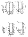
- FIGS. 2a, 2b This also applies to a trailer, shown in FIGS. 2a, 2b.
- the structure 3 is thus divided along a surface line 6 shown in dashed lines and a corresponding horizontal surface, the upper structure part 4 having a correspondingly larger plan for lowering above the lower structure part 5.
- guide rails 7 are arranged below the structure and connect the two parts to one another, so that the upper part with its rails can be slid along these rails in corresponding rails of the lower part.
- FIGS. 3a to 3c two doors are provided on the rear end wall of a box-shaped structure, only the left of which is shown in each case.
- These doors are divided into two wings 8 and 9, the upper wing 8 over the lower wing 9 at Lowering the upper construction part 4 on the lower construction part 5 can be lowered.
- a cranked hinge arrangement 10 is provided, the pivot point of the hinges being aligned in the axis 11.
- the hinges are necessary to ensure a stable door suspension, the lower hinge 12 of the upper wing 8 being arranged below the upper hinge 13 of the lower wing 9. This enables unhindered lifting or lowering of the upper structural part and thus the doors.
- the upper and lower wings 8, 9 can be connected to one another by guide rails 14 or the like.
- the upper guide rail 15 of the upper wing engages in the lower guide rail 14 of the lower wing, so that a lateral entanglement of the upper wing 8 to the lower wing 9 is prevented.
- the aerodynamic spoiler 16 is connected to the roof 18 of the driver's cab 2 by a joint 17.
- This spoiler 16 is guided in two rails 19, which are arranged on the roof of the structure. This allows the spoiler to adapt to the respective height of the upper part 4 of the structure.
- a seal 20 can be provided between the upper and lower parts 4 and 5 of the structure in order to prevent the ingress of dust and splash water into the interior.
- a safety device 21 can also be provided at the four opposite corners, or also in between, which, for example, consists of a self-locking lock, such as the one shown has become known, for example, for seat belts in motor vehicles. If the lifting device should fail due to breakage, this safety device prevents the upper part 4 of the structure from falling off.
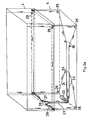
- 5a, 5b the cable arrangement for lifting and lowering the upper part 4 of the structure is shown.
- This arrangement consists essentially of an electric motor 22 with a gear and a gear, which acts on a chain 23 running along an end wall and on the floor and tensioned.
- the drive of the motor 22 is designed so that the chain 23 can be moved back and forth along its length.
- two cables 24, 25 are attached, which each run over deflection rollers 26 to the lower corners of the upper part 4 according to the arrows, where they are attached.
- the motor 22 is displaced in the corresponding direction of rotation, which, in accordance with the course of the cable pulls illustrated, enables this part to be lowered and raised.
- Fig. 5b a rope tension is shown, at wel
- the cables 31 run over deflection rollers 30 attached to both sides from the top of the upper part 4 to the lower edges of the upper part 4.
- a fastening device for example a plate 35, is fixedly arranged in or under the floor of the loading space.
- this plate 35 four times two holes are provided, through which the cores 36 and 37 are guided by two mutually cooperating Bowden cables 38, 39, the jackets of which are fastened to the front of the plate 35.
- Two Bowden cables 38, 39 each lead to four corner posts 40, 41, 42, 43 or other stiffening devices in the body parts 4, 5.
- two cooperating Bowden cables 38, 39 are each guided to a holding device 44 for a deflection roller 45, which is located in the upper region of the lower part 5 of the body structure.
- a deflection roller 45 which is located in the upper region of the lower part 5 of the body structure.
- the souls 37 of the Bowden cables 38 lead up to the ceiling of the upper part 4.
- the souls 36 of the Bowden cables 39 are guided over the rotatably mounted deflection roller 45 and fastened in the region of the lower edge of the upper part 5 which can be raised and lowered. This arrangement has been carried out four times within the body structure, so that smooth lifting and lowering can be achieved.
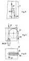
- FIGS. 7a and 7b also show special seals which are arranged on the inside of the upper part 4 in the lower region.
- the seals 46 consist of hollow rubber profiles with a cavity 47.
- this cavity is pressurized with air, whereby the seal between the two parts 4 and 5 is ensured.
Landscapes
- Engineering & Computer Science (AREA)
- Transportation (AREA)
- Mechanical Engineering (AREA)
- Chemical & Material Sciences (AREA)
- Combustion & Propulsion (AREA)
- Health & Medical Sciences (AREA)
- Public Health (AREA)
- Power-Operated Mechanisms For Wings (AREA)
- Body Structure For Vehicles (AREA)
- Vehicle Cleaning, Maintenance, Repair, Refitting, And Outriggers (AREA)
Applications Claiming Priority (2)
| Application Number | Priority Date | Filing Date | Title |
|---|---|---|---|
| DE3828184 | 1988-08-19 | ||
| DE19883828184 DE3828184A1 (de) | 1988-08-19 | 1988-08-19 | Karosserieanordnung fuer ein kraftfahrzeug oder einen anhaenger |
Publications (2)
| Publication Number | Publication Date |
|---|---|
| EP0359910A2 true EP0359910A2 (fr) | 1990-03-28 |
| EP0359910A3 EP0359910A3 (fr) | 1990-12-12 |
Family
ID=6361190
Family Applications (1)
| Application Number | Title | Priority Date | Filing Date |
|---|---|---|---|
| EP19890110552 Withdrawn EP0359910A3 (fr) | 1988-08-19 | 1989-06-10 | Agencement de carrosserie pour un véhicule à moteur ou remorque |
Country Status (2)
| Country | Link |
|---|---|
| EP (1) | EP0359910A3 (fr) |
| DE (1) | DE3828184A1 (fr) |
Cited By (5)
| Publication number | Priority date | Publication date | Assignee | Title |
|---|---|---|---|---|
| EP0495664A1 (fr) * | 1991-01-16 | 1992-07-22 | Christian Seaton Robinson | Véhicule à toit levable ou abaissable |
| GB2333069A (en) * | 1998-01-08 | 1999-07-14 | Mclaren International Ltd | Mobile hospitality units |
| WO2008106947A1 (fr) * | 2007-03-07 | 2008-09-12 | Holger Meyburg | Véhicule équipé d'une superstructure |
| AT510825A1 (de) * | 2010-12-06 | 2012-06-15 | Angel Ivanov Palashev | Werbeaufbau |
| CN114074720A (zh) * | 2020-08-13 | 2022-02-22 | 北汽福田汽车股份有限公司 | 车辆货箱及车辆 |
Families Citing this family (8)
| Publication number | Priority date | Publication date | Assignee | Title |
|---|---|---|---|---|
| DE9103544U1 (fr) * | 1991-03-22 | 1991-08-08 | Westfalia-Werke Franz Knoebel Und Soehne Kg, 4840 Wiedenbrueck, De | |
| US5400863A (en) * | 1993-04-09 | 1995-03-28 | Richardson; Paul A. | Air duct and furnace cleaning system and method |
| DE10104529A1 (de) * | 2001-01-31 | 2002-08-01 | Unicat Fahrzeugbau Gmbh | Kraftfahrzeug, insbesondere Expeditionsfahrzeug oder Wohnmobil, mit kofferartigem Aufbau |
| DE102010027716A1 (de) | 2010-07-20 | 2011-03-17 | Daimler Ag | Nutzfahrzeug mit einem Aufbau |
| DE102010046960A1 (de) | 2010-09-29 | 2011-05-12 | Daimler Ag | Windleiteinrichtung für einen Kraftwagen |
| DE102017001070A1 (de) | 2017-02-06 | 2018-08-09 | Alexander Schlecht | Multifunktionaler höhen verstellbarer Kofferaufbau |
| DE102017212341A1 (de) * | 2017-07-19 | 2019-01-24 | Bayerische Motoren Werke Aktiengesellschaft | Transportfahrzeug zum Transportieren von Gegenständen |
| DE102017220890A1 (de) * | 2017-11-22 | 2019-05-23 | Bayerische Motoren Werke Aktiengesellschaft | Karosserieelement für ein autonom fahrbares Fahrzeug |
Citations (6)
| Publication number | Priority date | Publication date | Assignee | Title |
|---|---|---|---|---|
| US2879103A (en) * | 1958-04-22 | 1959-03-24 | Robert D Hall | Telescoping cabin for trucks |
| GB863949A (en) * | 1958-09-17 | 1961-03-29 | Hugh England | Improvements in or relating to trailer caravans |
| FR1487064A (fr) * | 1966-07-19 | 1967-06-30 | Système de levage à câbles pour caravane télescopique | |
| US3809426A (en) * | 1972-08-28 | 1974-05-07 | Ratcliff Ind Inc | Mechanism for raising and lowering telescopic travel trailer |
| GB2059498A (en) * | 1979-08-15 | 1981-04-23 | Danbury Conversions Ltd | Elevating roof mechanism |
| DE3150707A1 (de) * | 1981-12-22 | 1983-07-14 | Bernhard 7988 Wangen Hensler | "einrichtungen zur hoehenverstellung von fahrzeugaufbauten" |
Family Cites Families (6)
| Publication number | Priority date | Publication date | Assignee | Title |
|---|---|---|---|---|
| US3061358A (en) * | 1959-06-15 | 1962-10-30 | Bishman Mfg Company | Truck body cover assembly |
| GB928640A (en) * | 1962-02-21 | 1963-06-12 | Robert Donald Hall | Camper for trucks |
| US4392682A (en) * | 1981-08-04 | 1983-07-12 | Norkus Jr Kasper | Expansible and retractable vehicle body |
| DE3211941A1 (de) * | 1982-03-31 | 1983-10-13 | Erich Köpf Fahrzeugbau GmbH & Co., 7957 Schemmerhofen | Kastenaufbau mit einem hubboden, insbesondere fuer viehtransportfahrzeuge |
| DE8219294U1 (de) * | 1982-07-06 | 1982-11-25 | Peter Amberger Spedition GmbH, 8074 Gaimersheim | Fahrzeug mit hubdach |
| DE8712666U1 (fr) * | 1987-09-19 | 1987-12-23 | Reitz, Otto Friedrich, 8221 Grabenstaett, De |
-
1988
- 1988-08-19 DE DE19883828184 patent/DE3828184A1/de not_active Withdrawn
-
1989
- 1989-06-10 EP EP19890110552 patent/EP0359910A3/fr not_active Withdrawn
Patent Citations (6)
| Publication number | Priority date | Publication date | Assignee | Title |
|---|---|---|---|---|
| US2879103A (en) * | 1958-04-22 | 1959-03-24 | Robert D Hall | Telescoping cabin for trucks |
| GB863949A (en) * | 1958-09-17 | 1961-03-29 | Hugh England | Improvements in or relating to trailer caravans |
| FR1487064A (fr) * | 1966-07-19 | 1967-06-30 | Système de levage à câbles pour caravane télescopique | |
| US3809426A (en) * | 1972-08-28 | 1974-05-07 | Ratcliff Ind Inc | Mechanism for raising and lowering telescopic travel trailer |
| GB2059498A (en) * | 1979-08-15 | 1981-04-23 | Danbury Conversions Ltd | Elevating roof mechanism |
| DE3150707A1 (de) * | 1981-12-22 | 1983-07-14 | Bernhard 7988 Wangen Hensler | "einrichtungen zur hoehenverstellung von fahrzeugaufbauten" |
Cited By (7)
| Publication number | Priority date | Publication date | Assignee | Title |
|---|---|---|---|---|
| EP0495664A1 (fr) * | 1991-01-16 | 1992-07-22 | Christian Seaton Robinson | Véhicule à toit levable ou abaissable |
| GB2333069A (en) * | 1998-01-08 | 1999-07-14 | Mclaren International Ltd | Mobile hospitality units |
| GB2333069B (en) * | 1998-01-08 | 2001-11-07 | Mclaren Internat Ltd | Hospitality unit |
| WO2008106947A1 (fr) * | 2007-03-07 | 2008-09-12 | Holger Meyburg | Véhicule équipé d'une superstructure |
| AT510825A1 (de) * | 2010-12-06 | 2012-06-15 | Angel Ivanov Palashev | Werbeaufbau |
| CN114074720A (zh) * | 2020-08-13 | 2022-02-22 | 北汽福田汽车股份有限公司 | 车辆货箱及车辆 |
| CN114074720B (zh) * | 2020-08-13 | 2022-12-30 | 北汽福田汽车股份有限公司 | 车辆货箱及车辆 |
Also Published As
| Publication number | Publication date |
|---|---|
| DE3828184A1 (de) | 1990-03-01 |
| EP0359910A3 (fr) | 1990-12-12 |
Similar Documents
| Publication | Publication Date | Title |
|---|---|---|
| EP0416539B1 (fr) | Dispositif d'accès pour véhicules automobiles, en particulier pour autobus | |
| DE2417140A1 (de) | Fahrbare rolltreppe | |
| EP0359910A2 (fr) | Agencement de carrosserie pour un véhicule à moteur ou remorque | |
| DE102013114590A1 (de) | Heckklappenträger mit Motorantrieb | |
| DE4329614C2 (de) | Einstieg für Schienenfahrzeuge | |
| EP0429033B1 (fr) | Escalier pour passagers d'avions | |
| WO2003097411A1 (fr) | Plancher de chargement pour un vehicule et dispositif de chargement | |
| EP2676824A2 (fr) | Structure pour le transports de biens | |
| DE1941940B2 (de) | Fahrzeug mit Hebevorrichtung für großvolumige Kästen, vorzugsweise aus Beton mit Ausnehmungen im Boden für teleskopisch längenveränderliche Beine der Hebevorrichtung | |
| DE102019206069B3 (de) | Vorrichtung zum Be- und/oder Entladen eines Innenraums eines Fahrzeugs und zum Erleichtern eines Einsteigens in und Aussteigens aus dem Fahrzeug | |
| DE4412689C2 (de) | Rollstuhldachkoffer | |
| EP0319665B1 (fr) | Conteneur | |
| EP0253263B1 (fr) | Véhicule à fourgon avec mécanisme de levage | |
| EP0688388A1 (fr) | Installation mecanique de stationnement | |
| DE4209535A1 (de) | Hebevorrichtung fuer ein abnehmbares stahlverdeck (hardtop) eines kraftfahrzeugs | |
| DE102015111842B4 (de) | Laderaumaufbau | |
| DE3028887A1 (de) | Unbewegliche nachruestvorrichtung an fahrzeugaufbauten | |
| EP0184002B1 (fr) | Dispositif de garage pour voitures | |
| DE10226730B4 (de) | Sargtransportvorrichtung zum Einbau in Fahrzeugen | |
| EP3744545B1 (fr) | Équerre coulissante arrière | |
| DE3818156A1 (de) | Geschlossener kastenwagen mit hinterer ladetuer | |
| DE202016105411U1 (de) | Rampenanordnung für Rollstühle zum Anbau an Fahrzeuge | |
| DE10341034A1 (de) | Pantographtür oder-klappe | |
| DE19836432A1 (de) | Hubtürsystem | |
| DE2038303A1 (de) | Vorrichtung zum Verladen von Kraftwagen in ein Schienenfahrzeug |
Legal Events
| Date | Code | Title | Description |
|---|---|---|---|
| PUAI | Public reference made under article 153(3) epc to a published international application that has entered the european phase |
Free format text: ORIGINAL CODE: 0009012 |
|
| AK | Designated contracting states |
Kind code of ref document: A2 Designated state(s): AT BE CH DE ES FR GB GR IT LI NL SE |
|
| PUAL | Search report despatched |
Free format text: ORIGINAL CODE: 0009013 |
|
| AK | Designated contracting states |
Kind code of ref document: A3 Designated state(s): AT BE CH DE ES FR GB GR IT LI NL SE |
|
| STAA | Information on the status of an ep patent application or granted ep patent |
Free format text: STATUS: THE APPLICATION IS DEEMED TO BE WITHDRAWN |
|
| 18D | Application deemed to be withdrawn |
Effective date: 19910613 |