EP0358433B1 - Baugerät und Bauverfahren - Google Patents
Baugerät und Bauverfahren Download PDFInfo
- Publication number
- EP0358433B1 EP0358433B1 EP89308941A EP89308941A EP0358433B1 EP 0358433 B1 EP0358433 B1 EP 0358433B1 EP 89308941 A EP89308941 A EP 89308941A EP 89308941 A EP89308941 A EP 89308941A EP 0358433 B1 EP0358433 B1 EP 0358433B1
- Authority
- EP
- European Patent Office
- Prior art keywords
- framework
- construction
- columns
- permanent
- building
- Prior art date
- Legal status (The legal status is an assumption and is not a legal conclusion. Google has not performed a legal analysis and makes no representation as to the accuracy of the status listed.)
- Expired - Lifetime
Links
- 238000010276 construction Methods 0.000 title claims description 184
- 230000007246 mechanism Effects 0.000 claims description 59
- 238000003466 welding Methods 0.000 claims description 17
- 238000000034 method Methods 0.000 claims description 8
- 239000004035 construction material Substances 0.000 claims description 4
- 230000001174 ascending effect Effects 0.000 claims description 2
- 230000008602 contraction Effects 0.000 claims 1
- 230000003028 elevating effect Effects 0.000 description 35
- 238000009434 installation Methods 0.000 description 4
- 238000009408 flooring Methods 0.000 description 3
- 230000007613 environmental effect Effects 0.000 description 2
- 238000005192 partition Methods 0.000 description 2
- 230000001419 dependent effect Effects 0.000 description 1
- 230000000694 effects Effects 0.000 description 1
- 230000008030 elimination Effects 0.000 description 1
- 238000003379 elimination reaction Methods 0.000 description 1
- 239000000463 material Substances 0.000 description 1
- 230000001681 protective effect Effects 0.000 description 1
Images


Classifications
-
- E—FIXED CONSTRUCTIONS
- E04—BUILDING
- E04G—SCAFFOLDING; FORMS; SHUTTERING; BUILDING IMPLEMENTS OR AIDS, OR THEIR USE; HANDLING BUILDING MATERIALS ON THE SITE; REPAIRING, BREAKING-UP OR OTHER WORK ON EXISTING BUILDINGS
- E04G21/00—Preparing, conveying, or working-up building materials or building elements in situ; Other devices or measures for constructional work
- E04G21/24—Safety or protective measures preventing damage to building parts or finishing work during construction
- E04G21/28—Safety or protective measures preventing damage to building parts or finishing work during construction against unfavourable weather influence
-
- E—FIXED CONSTRUCTIONS
- E04—BUILDING
- E04B—GENERAL BUILDING CONSTRUCTIONS; WALLS, e.g. PARTITIONS; ROOFS; FLOORS; CEILINGS; INSULATION OR OTHER PROTECTION OF BUILDINGS
- E04B1/00—Constructions in general; Structures which are not restricted either to walls, e.g. partitions, or floors or ceilings or roofs
- E04B1/35—Extraordinary methods of construction, e.g. lift-slab, jack-block
- E04B1/3522—Extraordinary methods of construction, e.g. lift-slab, jack-block characterised by raising a structure and then adding structural elements under it
- E04B1/3527—Extraordinary methods of construction, e.g. lift-slab, jack-block characterised by raising a structure and then adding structural elements under it the structure being a roof
-
- E—FIXED CONSTRUCTIONS
- E04—BUILDING
- E04G—SCAFFOLDING; FORMS; SHUTTERING; BUILDING IMPLEMENTS OR AIDS, OR THEIR USE; HANDLING BUILDING MATERIALS ON THE SITE; REPAIRING, BREAKING-UP OR OTHER WORK ON EXISTING BUILDINGS
- E04G21/00—Preparing, conveying, or working-up building materials or building elements in situ; Other devices or measures for constructional work
- E04G21/24—Safety or protective measures preventing damage to building parts or finishing work during construction
- E04G21/242—Safety or protective measures preventing damage to building parts or finishing work during construction for temporarily covering the whole worksite, e.g. building, trench
-
- E—FIXED CONSTRUCTIONS
- E04—BUILDING
- E04B—GENERAL BUILDING CONSTRUCTIONS; WALLS, e.g. PARTITIONS; ROOFS; FLOORS; CEILINGS; INSULATION OR OTHER PROTECTION OF BUILDINGS
- E04B1/00—Constructions in general; Structures which are not restricted either to walls, e.g. partitions, or floors or ceilings or roofs
- E04B1/35—Extraordinary methods of construction, e.g. lift-slab, jack-block
- E04B2001/3588—Extraordinary methods of construction, e.g. lift-slab, jack-block using special lifting or handling devices, e.g. gantries, overhead conveying rails
-
- Y—GENERAL TAGGING OF NEW TECHNOLOGICAL DEVELOPMENTS; GENERAL TAGGING OF CROSS-SECTIONAL TECHNOLOGIES SPANNING OVER SEVERAL SECTIONS OF THE IPC; TECHNICAL SUBJECTS COVERED BY FORMER USPC CROSS-REFERENCE ART COLLECTIONS [XRACs] AND DIGESTS
- Y10—TECHNICAL SUBJECTS COVERED BY FORMER USPC
- Y10S—TECHNICAL SUBJECTS COVERED BY FORMER USPC CROSS-REFERENCE ART COLLECTIONS [XRACs] AND DIGESTS
- Y10S52/00—Static structures, e.g. buildings
- Y10S52/12—Temporary protective expedient
Definitions
- the present invention relates to a construction apparatus and a construction method advantageously applicable to carrying out the construction of various structures including low buildings and high buildings using the least necessary labor and capable of enabling the construction work to be carried out regardless of weather conditions.
- a conventional construction method In constructing a multistory building, a conventional construction method erects columns for all the stories, lifts up the component members of the multistory building preassembled on the ground including slabs by lifting machines including cranes, and then joins the component members to the columns. Another conventional construction method stacks up stories one on another by completing a lower story, and then lifting the component members of an upper story by lifting machines including cranes and assembling the component members on the lower story.
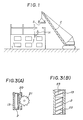
- Fig. 1 is an illustration of the latter conventional construction method, in which the first and second stories of a building have been completed and the third story is under construction.
- a worker H standing on the floor of the third story receives building members S lifted by a crane C, and then the worker H assembles the building members S by fixing the building members S at predetermined position by suitable means including welding and bolts.
- J. P. Pat. Provisional Pub. (Kokai) No. 62-244941 proposes a construction method which completes one story of a building in a plant installed in the first story of the building by using machines including industrial robots, and then pushes up the complete story by a distance corresponding to the story height. This procedure is repeated to complete a multistory building.
- DE-C-929089 describes a protective hut with working platforms and conveying devices which can be used around a transverse wall of a building under construction. It comprises four hydraulically adjustable supports to enable its height to be altered according to the progress of the work.
- the invention provides a method of constructing a multistory building in ascending order of stories by sequentially repeating the steps of: simultaneously extending extension columns provided on a framework placed on a completed structure of the building to form a working space over the completed structure; sequentially and one at a time contracting the extension columns to form spaces for receiving permanent columns therein between the framework and the completed structure and installing permanent columns in the spaces formed; installing beams between the adjacent permanent columns; executing construction work in a structure formed by the permanent columns and the beams to complete the structure; and sequentially repeating the steps in that order to construct the next upper structure.
- the invention also provides a construction apparatus comprising: a framework constructed above a completed structure of a building and extension columns provided on the framework, capable of extending downward to support the framework above the completed structure, a working space being formed between the framework and the completed structure; characterised in that the framework comprises at least four of said extension columns and in that each of said extension columns are capable of being contracted independently of each other to provide spaces for installing permanent columns on the completed structure.
- the extension columns provided on the framework are extended simultaneously to elevate the framework so that a temporary working space is formed between the framework and the underlying completed structure supporting the extension columns.
- the extended extension columns serve as temporary columns during construction work in the temporary work space over the underlying completed structure.
- the extension columns corresponding, respectively, to positions where permanent columns are to be installed are contracted sequentially one at a time to install the permanent columns sequentially at positions corresponding to the contracted extension columns.
- a working space provided with the permanent columns is formed under the framework.
- the extension columns are extended again simultaneously to form another temporary working space for constructing the next upper structure. Since the upper structures are constructed sequentially by extending and contracting the extension columns to secure a working space, the construction work can be easily controlled automatically, and the use of the construction apparatus in combination with automatic construction equipment enables automatic construction work.
- a roof is formed over the framework and an enclosure is formed around the framework to shield the working space from the outside. Accordingly, the construction work can be carried out without being affected by weather conditions and without giving public nuisance to the environment.
- the framework and roof of the construction apparatus may be incorporated into the building as a penthouse.
- the framework may be a temporary framework provided with a temporary roof and a temporary enclosure, which are the same in function as the foregoing roof and enclosure.
- the extension columns may be hydraulic cylinders, screw jacks, or a rack-and-pinion mechanism comprising pinions rotatably supported on the framework and rods provided with racks respectively engaging the pinions.
- Overhead traveling cranes detachably provided with construction robots may be provided on the framework.
- the traveling cranes and the construction robots are controlled on a cylindrical coordinate system or a polar coordinate system.
- Lifts each provided with a rotary floor for unloading the cargo at an optional angular position may be installed in the internal space of the building.
- a control room may be constructed in the upper space of the framework.
- a construction apparatus comprises a framework placed on a completed structure of a building under construction to form a working space for construction work including installing permanent columns, elevating means provided on the framework and capable of extending downward from the framework to elevate the same and to serve as temporary columns for forming the working space over the completed structure of the building, locking mechanism provided on the lower ends of the elevating means and removably fitting the completed structure of the building, and construction means provided on the framework for construction work in the working space.
- the locking mechanism is fitted with the upper ends of the permanent columns prior installed the underlying completed structure of the building.
- the holding means is provided on the framework and capable of extending downward from the framework to position and hold the permanent columns installed upright in the working space at the upper ends thereof.
- the permanent column has an engaging portion at the upper end thereof and the holding means have a fitting portion at the lower end thereof opposite to the upper end of the permanent column for positioning each other.
- the permanent column has an engaging portion at the upper end thereof.
- the permanent column has a fitting end portion at the lower end thereof fitting the engaging portion of the other permanent column prior installed the underlying completed structure of the building.
- the locking mechanism have a fitting portion at the lower end thereof opposite to the upper end of the permanent column to engaging the engaging portion of the permanent column for positioning each other.
- the framework can be positioned correctly relative to the completed structure of the building and the framework is restrained from lateral movement relative to the completed structure by the engagement of the fitting portion of the locking mechanism provided on the lower ends of the elevating means serving as the temporary columns and the engaging portion formed in the upper ends of the permanent columns of the underlying completed structure of the building, so that the framework can be supported securely on the completed structure of the building under construction and the earthquake resistance of the framework during the construction work is improved.
- the framework is elevated by downwardly extending the elevating means serving as the temporary columns to form the working space, the permanent columns are installed in the working space by the construction means, the permanent columns is firmly positioned one at a time by extending the holding means, and the permanent columns and beams previously attached to the permanent columns or attached to the permanent columns in the working space are joined firmly to complete the structure of an upper story on the underlying previously completed structure of the building.
- the framework is elevated again by the elevating means to start constructing the structure of the next upper story.
- the framework is elevated repeatedly to form working spaces sequentially for the upper stories to proceed with sequentially constructing the upper stories from the lower to the upper stories.
- Such regular upward shift of the working space and the construction within the working space facilitate the automated control of elevating the framework, driving the holding means and the operation of the construction means, and enables automated construction work using automatic construction machines.
- the fitting end portions formed on the lower ends of the permanent columns, and the engaging portions formed in the upper ends of the permanent columns bring the permanent columns for the upper structure into alignment with the permanent columns of the underlying structure in installing the permanent columns for the upper structure, so that the permanent columns for the upper structure are joined correctly and easily to those of the underlying structure.
- the fitting portions formed on the lower ends of the holding means engage the engaging portions formed in the upper ends of the permanent columns, the permanent columns are positioned easily and held stably, the support of the framework is reinforced and hence the earthquake resistance of the framework during the construction is improved.
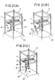
- the construction apparatus shown in Figs. 2(A) to 2(F) by way of example comprises, as principal components, a framework 3 (either permanent or temporary) constructed on a previously completed structure of a building 10 to form a working space 14 between the framework 3 and the underlying structure, and extension columns 1 provided on the framework 3, capable of extending downward from the framework 3 to serve as temporary columns for forming the working space 14 between the framework 3 and the underlying structure.
- the extension columns 1 may be capable of being individually contracted to form a space 15 between the lower end thereof and the underlying structure of the building 10 for receiving a permanent column 6 therein.
- the framework 3 is provided with a roof 16 to cover the working space 14.
- extension columns 1 are hydraulic cylinders each having a rod 2.
- the stroke of the rod 2 is slightly greater than the story height of a structure to be constructed on the underlying structure of the building 10.
- Each of the extension column 1 may be, as shown in Fig. 3(A), a combination of a rod 2 provided with a rack 20 along the entire length thereof, a sheath 13 fixed to the framework 3 and slidably receiving the rod 2 therein, and a pinion 21 rotatably supported on the sheath 13 and engaging the rack 20 to extend or contract the rod 2 along the sheath 13 or may be, as shown in Fig. 3(B), a combination of a rod 2 externally provided with a helical thread 22, and a sheath 13 internally provided with a helical groove 23 engaging the helical thread 22 of the rod 2, which is similar to a screw jack.
- the rod 2 is extended or contracted by rotating the rod 2 relative to the sheath 13.
- the framework 3 When the framework 3 is for temporary use, the framework 3 is formed in a shape similar in the plan to the shape of the upper surface of the underlying structure of the building 10, for example, a rectangular shape as shown in Figs. 2(A) to 2(F). When the framework 3 is for permanent use, the framework 3 is formed so as to support the roof, not shown, of a building to be constructed. The extension columns 1 are fixed to the framework 3 so as to support the same on the underlying structure of the building 10.
- a traveling crane 5 is supported on opposite beams 3a and 3b of the framework 3 for travel along the beams 3a and 3b, and a welding robot 4, for example, is mounted removably on the traveling crane 5.
- the rods 2 of the four extension columns 1 are extended simultaneously to their full length to form the working space 14 between the framework 3 and the underlying structure of the building 10.
- the rods 2 serve as temporary columns.
- the rod 2 of one of the extension columns 1 is fully retracted to form a space 15 for receiving a permanent column 6 between the lower end of the rod 2 and the underlying structure of the building 10.
- the framework 3 is supported by the other three extension columns 1.
- the construction apparatus is provided with far more than four extension columns 1 to support the framework 3 by far more than four rods 2, and hence the framework 3 can be supported securely even if some of the rods 2 are fully retracted.
- a permanent column 6 is installed in the space 15 below the contracted extension column 1.
- the welding robot 4 is removed from the traveling crane 5 and a column installing robot 9 capable of gripping the permanent column 6 is mounted on the traveling crane 5 to carry and install the permanent column 6.
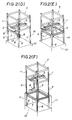
- the permanent column 6 is fixed firmly to the underlying structure of the building 10, for example, by welding while the rod 2 of the extension column 1 presses the permanent column 6 against the underlying structure of the building 10. Then, the rod 2 of another extension column 1 is fully retracted and another permanent column 6 is installed fixedly on the underlying structure through the same procedure.
- the permanent columns 6 are installed below the four extension columns 1 on the underlying structure by repeating the same procedure, while the column installing robot 9 is moved to relevant positions by the traveling crane 5.
- the column installing robot 9 is changed for a beam installing robot 12, and then beams 7 are joined to the permanent columns 6 by using the beam installing robot 12.
- the beam 7 In joining the beam 7 to the permanent columns 6, the beam 7 is extended between opposite beam joints 8 attached previously to the permanent columns 6, and then the beam 7 is fixed to the beam joints 8 by suitable means, such as welding or bolting.
- the beam installing robot 12 is moved to relevant positions in joining the all beams 7 to the permanent columns 6.
- Fig. 2(E) shows a stage of the construction work immediately after the completion of installation of the beams 7.
- the beams 7 are joined to the beam joints 8 by both welding and bolting; that is, first all the beams 7 are installed between and fastened with bolts and nuts to the beam joints 8 by using the beam installing robot 12, the beam installed robot 12 is changed for the welding robot 4, and then the beams 7 are welded to the beam joints 8 by using the welding robot 4.
- the welding robot 4 is used also for welding floor slabs to the beams 7.
- the stories of the building are constructed sequentially from the lower stories to the upper stories to complete the building.
- the construction apparatus is disassembled and removed after completing the uppermost story to complete the construction work.
- the component members of the extension columns 1, the rods 2 and the framework 3 are the same strength, respectively, as the permanent columns 6 and the beams 7, the work for disassembling and removing the construction apparatus is simplified because most of the component members of the construction apparatus can be utilized for the structure of the uppermost story.
- the framework 3 is a permanent framework
- the component members of the construction apparatus except the roof, the framework 3 and the extension columns 1 are removed after constructing the structure of the uppermost story, and then the uppermost story is finished to complete the construction of the building.
- the sheath 13 and the rod 2 are designed so that the extension column 1 is equivalent size and strength to the permanent column 6 when the rod 2 is fully retracted into the sheath 13.
- Fig. 4 shows a construction apparatus in a first embodiment according to the present invention as applied to practical construction work, in which parts like or corresponding to those previously described with reference to Fig. 2(A) to 2(F), 3(F) and 3(B) are denoted by the same referecne characters.
- FIG. 4 Shown in Fig. 4 is the construction apparatus embodying the present invention as applied to the construction of an annular building 10 requiring the least necessary workers.
- An elevator shaft 30 installed an elevator 31 is constructed in the central space of the building 10 so that the elevator 31 can transport construction materials including permanent columns 6 and beams 7.
- a framework 3 is a temporary framework
- the framework 3 is formed in a shape substantially the same in the horizontal projection as the horizontal section of the building 10.
- a control room 32 is constructed on the framework 3.
- the framework 3 is a permanent framework
- the framework 3 and a roof 16 formed on the framework 3 are incorporated into the building 10.
- the control room 32 is constructed in a space under the roof 16.
- Cylindrical buildings and semispherical buildings facilitate the accurate control of construction robots by using a control system under a cylindrical coordinate system or a polar coordinate system, which enables the building to be constructed at a reduced construction cost.
- An operator operates a controller 33 including a computer and installed in the control room 32 to carry out all the steps of the construction work previously described with reference to Figs. 2(A) to 2(F) automatically.
- a truck 34 loaded with permanent columns 6 is lifted to a story under construction by the elevator 31 from the ground, the permanent columns 6 are carried and installed sequentially at predetermined positions below extension columns 1 by a column installing robot 9 mounted on a traveling crane 5 (Fig. 2(B)), and then the permanent columns 6 are welded to the upper ends of the permanent columns 6 of the underlying story at positions near the floor slabs 35 by a welding robot 4.
- a truck 36 loaded with beams 7 is lifted to the story by the elevator 31 from the ground, the beams 7 are installed fixedly between the opposite beam joints 8 of the permanent columns 6 by a beam installing robot 12.
- the floor of the elevator 31 is rotatable through an angle of 360° to direct the trucks 34 and 36 in a desired direction so that the trucks 34 and 36 are able to move to a desired position suitable for installing the permanent columns 6 and the beams 7.
- construction work necessary for the story including attaching external wall panels 11 by means of quick fasteners 37, flooring the floor slabs 35 and hanging the ceiling is carried out by construction robots mounted on the traveling cranes 5.
- the rods 2 of the extension columns 1 are extended simultaneously to form a working space for construction work to construct the next upper story. Then the next upper story is constructed in the same manner as described above.
- the construction apparatus and the control room 32 are removed after the completion of construction of the uppermost story, and then a roof is constructed.
- the roof 38 constructed on the framework 3 may also be used a permanent roof to be incorporated into the building 10 if the strength of the roof 38 is the same as those of the permanent one.
- the control room 32 and tie components of the construction apparatus except the framework 3, the roof 16 and the extension columns 1 are disassembled and removed after completing the uppermost story. If required, the equipment of the control room 32 including the controller 33 are removed and the control room 32 may be left as it is as the uppermost story of the building 10.
- the framework 3 is a temporary framework
- the framework 3 is covered with the temporary roof 38 and enclosed with a temporary enclosure 39 to arrest noise generated by the construction work, to prevent the influence of environmental radiowaves and electromagnetic waves on electrical communication between the controller 33 installed in the control room 32 and the construction equipment including the construction robots and to shield the control room 32 and the working space 14 from rain and wind.
- the framework 3 is a permanent framework
- the framework 3 is covered and enclosed with the roof 16 having an enclosure hanging from the periphery of the roof 16 for the same purposes as those of the temporary roof 38 and the temporary enclosure 39.
- Providing the roof 16 and the enclosure for the permanent framework 3, or the temporary roof 38 and the temporary enclosure 39 for the temporary framework 3 with a soundproof capability and a radiowave and electromagnetic wave intercepting capability enables maintaining the working environment in a satisfactory condition and prevents the uncontrolled operation of the computer of the controller 33 and the construction robots.
- the maximum length of the extension columns 1, namely, the length of the extension columns 1 when the rods 2 are fully extended may be such as corresponding to twice the story height of the building 10 or greater, permanent columns having a length corresponding to twice the story height of the building 10 or greater can be installed.
- Shielding the working space by the roof and the enclosure enables the regular progress of the construction work regardless of weather conditions.
- the construction apparatus of the present invention is applicable to the higher heavy weight buildings and can be fabricated at a reduced cost because the extension columns of the construction apparatus of the present invention support only the temporary or permanent roof, the temporary or permanent framework, the temporary enclosure and the control room including the control equipment.
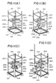
- a construction apparatus of the second embodiment of the present invention comprises a framework 203 placed on a completed structure of a building 210 under construction to form a working space 214 for construction work including installing permanent columns 206, elevating mechanisms 207 provided on the framework 203 and capable of extending downward from the framework 203 to elevate the same and to serve as temporary columns for forming the working space 214 over the completed structure of the building 210, locking mechanism provided on the lower ends of the elevating mechanism 207 and removably fitting the completed structure of the building 210, and construction machines provided on the framework 203 for construction working the working space 214.
- a holding mechanisms 201 are provided on the framework 203 and capable of extending downward from the framework 203 to position and hold permanent columns 206 installed in the working space at the upper ends thereof.
- Construction machines include a traveling crane 205, construction robots, such as a column installing robot 209, a beam installing robot 291, external wall setting robot 292 and a welding robot 204.
- the locking mechanisms are fitted with the upper ends of the permanent columns 206 prior installed the underlying completed structure of the building 210.
- the permanent column 206 has a conical recess 206y at the upper end thereof and the holding mechanism 201 has a conical projection 202x at the lower end thereof opposite to the upper end of the permanent column 206 for positioning each other.
- the permanent column 206 has a conical recess 206y at the upper end thereof.
- the permanent column 206 has a conical projection 206x at the lower end thereof fitting the conical recess 206y of the other permanent column 206 prior installed the underlying completed structure of the building 210.
- the locking mechanism have a conical projection 208x at the lower end thereof opposite to the upper end of the permanent column 206 to engaging the conical recess 206y of the permanent column 206 for positioning each other. It is also possible to change the conical projections 202x, 206x and 208x for conical recesses and the conical recesses 206y for conical projections or to change the conical recesses 206y for simple holes.
- the two holding mechanism 201 are provided diagonally opposite to each other on the framework 203, and the two elevating mechanisms 207 are provided diagonally opposite to each other on the framework 203.
- a practical construction apparatus is provided with more than two holding mechanisms 201 and more than two elevating mechanisms 207.
- the holding mechanism 201 is a hydraulic actuator having a rod 202 slidably received in a cylinder for projection and retraction.
- Each holding mechanism 201 may be constructed, instead of the hydraulic actuator, such as shown in Fig. 3(A) or Fig. 3(B).
- the elevating mechanism 207 comprises a hollow shaft, a post 208 having a length slightly longer than twice the story height of the building 210 and received slidably in the hollow shaft, and a hydraulic device, not shown, for moving the post 208.
- each elevating mechanism 207 is provided on the lower end thereof with a conical projection 208x.
- Each permanent column 206 is provided in the upper end thereof with a conical recess 206y fitting the conical projection 208x, and a conical projection 206x similar to the conical projection 208x of the post 208 on the lower end thereof.
- a conical projection 202x similar to the conical projection 206x is formed on the lower end of the rod 202 of the holding mechanism 201.
- the conical projections 208x of the posts 208, the conical projections 206x of the permanent columns 206 and the conical projections 202x of the rods 202 are capable of engaging the conical recesses 206y of the permanent columns 206.
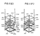
- the holding mechanisms 201 and the elevating mechanisms 207 are attached to the framework 203 having a shape in plan substantially the same as the shape of the upper surface of a completed structure of the building 210 (a rectangular shape, in the example shown in Figs. 5(A) to 5(F)) respectively at the four vertical edges thereof.
- the holding mechanisms 201 and the elevating mechanisms 207 are attached at appropriate intervals to the periphery of a framework similar to the framework 203.
- a traveling crane 205 is mounted on the opposite beams 203a and 203b of the framework 203, and a column installing robot 209 is held removably on the traveling crane 205.
- the conical projections 208x of the posts 208 of the elevating mechanisms 207 are fitted in the conical recesses 206y of the permanent columns 206 of the underlying completed structure of the building 210 to position the framework 203 correctly relative to the underlying completed structure of the building 210.
- the engagement of the conical projections 208x and the conical recesses 206y restrains the posts 208 from lateral movement to support the framework 203 stably so that the earthquake resistance of the framework 203 is improved.
- the two elevating mechanisms 207 are disposed diagonally opposite to each other, and hence the support of the framework 203 seems unstable.
- far more than two elevating mechanisms are arranged at appropriate intervals to support the framework 203 stably.
- the hydraulic devices of the elevating mechanisms 207 are driven to project the posts 208 downward, and thereby the framework 203 is elevated to form the working space 214 over the completed structure of the building 210 as shown in Fig. 5(A). In this state, spaces 215 for receiving the permanent columns 206 are formed directly below the retracted rods 202 of the holding mechanisms 201.
- the column installing robot 209 installs a permanent column 206 in the space 215 directly below the rod 202 of the holding mechanism 201 so that the conical projection 206x formed on the lower end of the permanent column 206 is received in the conical recess 206y formed in the upper end of the permanent column 206 of the underlying completed structure of the building 210. Even if the conical projection 206x is deviated slightly from the conical recess 206y in installing the permanent column 206, the conical projection 206x and the conical recess 206y can be closely engaged by applying a small pressure to the permanent column 206. Therefore, the column installing robot 209 need not be controlled highly accurately, which facilitates the installation of the permanent column 206.
- the rod 202 of the holding mechanism 201 is projected slightly so that the conical projection 202x of the rod 202 engage the conical recess 206y formed in the upper end of the permanent column 206 to position and hold the permanent column 206 in place, and then the permanent column 206 is welded to the completed structure of the building 210 by the welding robot 204 removably held on the traveling crane 205.
- the permanent column 206 is brought into alignment with the rod 202 by the engagement of the conical projection 202x of the rod 202 and the conical recess 206y of the permanent column 206 when the permanent column 206 is pressed by the rod 202, which facilitates the correct positioning of the permanent column 206. Since the upper end and the lower end of the permanent column 206 is engaged with the rod 202 and the underlying permanent column, the permanent column 206 is held securely, the support of the framework 203 is reinforced and hence the earthquake resistance of the framework 203 during the construction is improved. Subsequently, the other permanent column 206 is installed and fixed to the underlying permanent column 206 in the same manner.
- the post 208 of the elevating mechanism 207 is retracted by driving the hydraulic device of the elevating mechanism 207 to form a space 215 for installing a permanent column 206 directly below the post 208, and then the permanent column 206 is installed and fixed to the underlying permanent column 206 of the completed structure of the building 210 in the same manner as that for installing and fixing the permanent column 206 in the space 215 directly below the rod 202 of the holding mechanism 201. Then, a permanent column 206 is installed and fixed to the underlying permanent column 206 at a position diagonally opposite the previously fixed permanent column 206 as shown in Fig. 5(E).
- beams 260 joined beforehand to the adjacent permanent columns 206 are welded together at appropriate time by the welding robot 204 held on the traveling crane 205 as shown in Fig. 5(F). It is also possible to prepare the beams 260 and the permanent columns 206 separately and to weld each beam 260 at the opposite ends thereof to beam joints, not shown, attached to the opposite sides of the adjacent permanent columns 206.
- the elevating mechanisms 207 are driven again to elevate the framework 203 as shown in Fig. 5(A) to start the construction of the next upper story, in which the steps shown in Figs. 5(A) to 5(F) are repeated.
- the construction apparatus including the framework 203 and the holding mechanisms 201 is disassembled and removed, and then the uppermost story is finished to complete the building 210.
- the holding mechanisms 201, the framework 203 and the elevating mechanisms 207 can be used as the components of the structure of the uppermost story, which simplifies or enables the omission of disassembling and removing the construction apparatus.
- Fig. 6 is a schematic perspective view illustrating a construction apparatus of the third embodiment as applied to a practical construction work, in which parts like or corresponding to those previously described with reference to Figs. 5(A) to 5(F), 3(A) and 3(B) are denoted by the same reference characters.
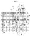
- Fig. 7 is a schematic plan view of an essential portion of the construction apparatus shown in Fig. 6,
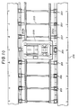
- Fig. 8 is a sectional view taken on line XI-XI in Fig. 7
- Fig. 9 is a sectional view taken on line XII-XII in Fig. 7
- Figure 10 is a sectional view taken on line XIII-XIII in Fig. 7 , and
- Fig. 11 is a plan view as viewed in the direction of an arrow XIV in Fig. 7.
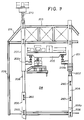
- a building 210 shown in Fig. 6 is substantially rectangular in plan.
- An elevator shaft is constructed in the central space of the building 210, and an elevator is installed in the elevator shaft to transport construction materials including permanent columns 206 and beams 207.
- the construction apparatus is substantially the same in plan as the building 210.
- a framework 203 included in the construction apparatus is provided with a cover 216.
- a control room 232 is formed in a space covered with the cover 216.
- the construction apparatus is controlled by a computerized controller 233 installed in the control room 232 and operated by an operator for automatic execution of the construction steps shown in Figs. 5(A) to 5(F).
- a plurality of elevating mechanisms 207 are arranged in pairs. Each pair of elevating mechanisms 207 are disposed adjacently. While one of the elevating mechanisms 207 of each pair is contracted the other is extended. Accordingly, the framework 203 is supported alternately by one of the elevating mechanisms 207 of each pair and the other of the same.
- a hydraulic mechanism 270 for operating the elevating mechanism 207 is disposed on top of the framework 203 to project a post 208 downward from the framework 203 and to retract the post 208 upward.
- the framework 203 is firmly engaged with the post 208 even if the horizontal force such as the earthquake or the wind force acts the framework 203, therefore the vibration resistance of this construction appratus is improved still more.
- Each of permanent columns 206 transported from the ground to a story under construction by an elevator is transported to and installed at a position specified by the computerized controller 232 by a column installing robot 209 held on a traveling crane 205, and then the permanent column 206 is welded to the upper end of a permanent column 206 of the underlying completed structure of the building 210 by a welding robot 204. Then, beams 260 previously attached to the adjacent permanent columns 206 are welded together by the welding robot 204.
- the permanent column 206 is formed higher than one story height, and attached integrally the beams 260 extending both sides thereof at the upper end and the lower end of the permanent column 206, respectively. Then in a practical work, the beam 260 of the upper end of the permanent column 206 is welded the beam 260 of the lower end of the permanent column 206 which is adjecent to the former, as the result the construction work of the permanent columns 206 and the beams 260 in the one story is finished by setting the half number of columns 206 and beams 260, in considering the column and the beam installation of each story. Therefore, the efficiency of the construction work is improved in comparing the case which all the columns 206 and the beams 260 is setting in each story.
- construction work necessary for completing the story including installing external wall panels 211 is carried out by construction robots held on the traveling cranes 205. Then, the elevating mechanisms 207 are driven to elevate the framework 203 to construct a structure for the next upper story.
- the structure of the next upper story is constructed by repeating the same steps of construction work. After the structures of all the stories of the building 210 have been constructed, the construction apparatus and the control room are removed, and then the roof of the building 210 is constructed.
- the cover 216 provided on the framework 203 consists of a temporary roof 238 and a temporary enclosure 239.
- the cover 216 arrest noise generated by the construction work, prevents the influence of disturbance, such as environmental radiowaves, on electrical signals given from the computerized controller 233 installed in the control room 232 to the construction machines including the construction robots, and to shield the control room 232 and the story under construction from rain and wind.
- the holding mechanisms 201, the framework 203 and the elevating mechanisms 207 may be incorporated into the building 210.
- the temporary roof 238 may be formed of the same materials and in the same construction as those of the permanent roof of the building 210 to incorporate the temporary roof 238 to the building 210 as the permanent roof.
- the posts 208 of the elevating mechanisms 207 of the construction apparatus support only the framework 203, the cover 216 and the construction equipments provided on the framework 203. Accordingly, the construction apparatus has a sufficient earthquake resistance and is applicable to the construction of buildings unlimited in height.
- the above construction apparatus according to the second embodiment has the following advantages.
- the engagement of the conical projections of the locking mechanisms provided on the lower ends of the elevating mechanisms and the conical recesses formed in the upper ends of the permanent columns positions the framework accurately relative to the completed structure of the building, prevents the lateral movement of the framework relative to the completed structure of the building, supports the framework stably and improves the earthquake resistance of the construction apparatus during the construction.
- the conical projections formed on the lower ends of the holding means engage the conical recesses formed in the upper ends of the permanent columns, the permanent columus are positioned easily and held stably, the support of the framework is reinforced and hence the earthquake resistance of the framework during the construction is improved.
Landscapes
- Engineering & Computer Science (AREA)
- Architecture (AREA)
- Civil Engineering (AREA)
- Structural Engineering (AREA)
- Mechanical Engineering (AREA)
- Physics & Mathematics (AREA)
- Electromagnetism (AREA)
- Conveying And Assembling Of Building Elements In Situ (AREA)
Claims (21)
- Verfahren zum Bauen eines mehrstöckigen Gebäudes in aufsteigender Reihenfolge der Stockwerke durch aufeinanderfolgendes Wiederholen folgender Schritte:
Gleichzeitiges Verlegen von Ausziehstützen ( 1,207), die an einem Rahmenaufbau (3,203) vorgesehen sind, der auf einem fertiggestellten Aufbau (10,210) des Gebäudes angeordnet ist, um einen Arbeitsraum (14,214) über dem fertiggestellten Aufbau auszubilden,
aufeinanderfolgendes und einmal zu einer Zeit erfolgendes Zusammenziehen der Ausziehstützen (1,207) zum Ausbilden von Räumen (15,215) für die Aufnahme permanenter Stützen (6,206) darin zwischen dem Rahmenaufbau (3,203) und dem fertiggestellten Aufbau (10,210) und Installieren permanenter Stützen in den so gebildeten Räumen,
Installieren von Trägern (7,260) zwischen den benachbarten permanenten Stützen (6,206),
Ausführen von Baumaßnahmen in einem Aufbau, der durch die permanenten Stützen (6,206) und die Träger (7,260) ausgebildet ist, um den Aufbau fertigzustellen, und
aufeinanderfolgendes Wiederholen der Schritte in der Reihenfolge, daß der nächste darüberliegende Aufbau ausgebildet wird. - Verfahren nach Anspruch 1,
umfassend den weiteren Schritt des Installierens permanenter Stützen (206) in Räumen zwischen dem fertiggestellten Aufbau (210) und einer Halteeinrichtung (201), die in dem Rahmenaufbau (203) vorgesehen ist, wobei dieser weitere Schritt nach dem Ausziehen der Ausziehstützen (207) und vor dem aufeinanderfolgenden Zusammenziehen der Ausziehstützen stattfindet. - Baugerät umfassend
einen Rahmenaufbau (3,203), der über einem fertiggestellten Aufbau (10,210) eines Gebäudes angeordnet ist, und Ausziehstützen (1,207), die an dem Rahmenaufbau (3, 203) vorgesehen sind und nach unten ausgezogen werden können, um den Rahmenaufbau über dem fertiggestellten Aufbau abzustützen,
einen Arbeitsraum (14,214), der zwischen dem Rahmenaufbau (3,203) und dem fertiggestellten Aufbau (10,210) ausgebildet ist,
dadurch gekennzeichnet,
daß der Rahmenaufbau (3,203) wenigstens vier solcher Ausziehstützen (1,207) umfaßt und daß jede dieser Ausziehstützen (1,207) unabhängig von jeder anderen zusammengezogen bzw. verkürzt werden kann zum Ausbilden von Räumen für die Installation permanenter Stützen (6,206) auf dem fertiggestellten Aufbau (10, 210). - Baugerät nach Anspruch 3,
wobei der Rahmenaufbau (3,203) mit einem Dach (16,216) zum Abdecken des Arbeitsraumes (14,214) versehen ist. - Baugerät nach Anspruch 3,
wobei der Rahmenaufbau ein vorübergehender Rahmenaufbau ist. - Baugerät nach Anspruch 5,
wobei der Rahmenaufbau mit einer zeitweiligen Abdeckung (38,238) zum Abdecken des Arbeitsraumes (14,214) versehen ist. - Baugerät nach einem der Ansprüche 3 bis 6,
wobei die Ausziehstützen (1,207) hydraulische Zylinder sind. - Baugerät nach einem der Ansprüche 3 bis 7,
wobei weiterhin Baueinrichtungen vorgesehen sind an dem Rahmenaufbau für Baumaßnahmen in dem Arbeitsraum (14, 214). - Baugerät nach Anspruch 8,
wobei der Rahmenaufbau (3,203) mit einem Laufkran (5, 205) zum abnehmbaren Halten der Baueinrichtung versehen ist. - Baugerät nach einem der Ansprüche 8 oder 9,
wobei die Baueinrichtung ein Roboter (9,209) zum Installieren einer Stütze, ein Schweißroboter (4,204), ein Roboter (291) zum Installieren einer Stütze oder ein Roboter (292) zum Setzen einer Außenwand ist. - Baugerät nach Anspruch 9 oder 10,
wobei der Laufkran (5,205) und die Baueinrichtung auf einem zylindrischen Koordinatensystem gesteuert werden. - Baugerät nach Anspruch 9 oder 10,
wobei der Laufkran (5,205) und die Baueinrichtung an einem polaren Koordinatensystem gesteuert werden. - Baugerät nach einem der Ansprüche 3 bis 12,
wobei innerhalb des fertiggestellten Aufbaus des Gebäudes ein Aufzug (31) für den Transport von Baumaterial in den inneren Raum von diesem installiert ist und der Aufzug eine drehbare Bühne aufweist, um das Baumaterial in eine beliebige Richtung abgeben zu können. - Baugerät nach einem der Ansprüche 3 bis 13,
wobei ein Steuerraum (32,232) im oberen Teil des Rahmenaufbaus ausgebildet ist. - Baugerät nach einem der Ansprüche 3 bis 14,
umfassend weiterhin einen Sperrmechanismus, der an den unteren Enden der Ausziehstützen (207) vorgesehen ist und abnehmbar am fertiggestellten Aufbau (210) des Gebäudes angebracht ist. - Baugerät nach Anspruch 15,
wobei der Sperrmechanismus an den oberen Enden der permanenten Stützen (206) angebracht ist, die vorher installiert wurden und in dem darunterliegenden fertiggestellten Aufbau (210) des Gebäudes angeordnet sind. - Baugerät nach einem der Ansprüche 3 bis 16,
wobei jede dieser permanenten Stützen (206) einen Eingriffsabschnitt (206y) an deren oberem Ende aufweist. - Baugerät nach Anspruch 17,
wobei Halteeinrichtungen (201) an dem Rahmenaufbau (203) vorgesehen sind, die sich von dem Rahmenaufbau nach unten erstrecken können, um die permanenten Stützen (206), die aufrecht in dem Arbeitsraum (214) an den oberen Enden davon installiert sind, zu positionieren und zu halten. - Baugerät nach Anspruch 18,
wobei jede dieser Halteeinrichtungen (201) einen Paßabschnitt (202x) am unteren Ende davon dem oberen Ende einer der permanenten Stützen (206) gegenüberliegend zum gegenseitigen Positionieren aufweist. - Baugerät nach einem der Ansprüche 17 bis 19,
wobei die permanente Stütze (206) einen Paßabschnitt (206x) an ihrem unteren Ende aufweist, der auf den Eingriffsabschnitt (206y) der anderen permanenten Stütze angepaßt ist, die vorher installiert wurde und in dem darunterliegenden fertiggestellten Aufbau (210) des Gebäudes angeordnet ist. - Baugerät nach einem der Ansprüche 17 bis 20,
wobei der Sperrmechanismus einen Paßabschnitt (208x) an seinem unteren Ende dem oberen Ende der permanenten Stütze (206) gegenüberliegend aufweist, um mit dem Eingriffsabschnitt (206y) der permanenten Stütze zum gegenseitigen Positionieren in Eingriff zu treten.
Priority Applications (1)
| Application Number | Priority Date | Filing Date | Title |
|---|---|---|---|
| EP92200399A EP0487516B1 (de) | 1988-09-05 | 1989-09-05 | Baugerät und Bauverfahren |
Applications Claiming Priority (6)
| Application Number | Priority Date | Filing Date | Title |
|---|---|---|---|
| JP222049/88 | 1988-09-05 | ||
| JP222048/88 | 1988-09-05 | ||
| JP63222049A JPH0759831B2 (ja) | 1988-09-05 | 1988-09-05 | 建設装置 |
| JP63222048A JPH0759830B2 (ja) | 1988-09-05 | 1988-09-05 | 建設装置 |
| JP192680/89 | 1989-07-27 | ||
| JP19268089A JPH07116845B2 (ja) | 1989-07-27 | 1989-07-27 | 建設装置 |
Related Child Applications (1)
| Application Number | Title | Priority Date | Filing Date |
|---|---|---|---|
| EP92200399.1 Division-Into | 1992-02-12 |
Publications (3)
| Publication Number | Publication Date |
|---|---|
| EP0358433A2 EP0358433A2 (de) | 1990-03-14 |
| EP0358433A3 EP0358433A3 (en) | 1990-07-18 |
| EP0358433B1 true EP0358433B1 (de) | 1994-01-05 |
Family
ID=27326651
Family Applications (2)
| Application Number | Title | Priority Date | Filing Date |
|---|---|---|---|
| EP89308941A Expired - Lifetime EP0358433B1 (de) | 1988-09-05 | 1989-09-05 | Baugerät und Bauverfahren |
| EP92200399A Expired - Lifetime EP0487516B1 (de) | 1988-09-05 | 1989-09-05 | Baugerät und Bauverfahren |
Family Applications After (1)
| Application Number | Title | Priority Date | Filing Date |
|---|---|---|---|
| EP92200399A Expired - Lifetime EP0487516B1 (de) | 1988-09-05 | 1989-09-05 | Baugerät und Bauverfahren |
Country Status (5)
| Country | Link |
|---|---|
| US (2) | US5022199A (de) |
| EP (2) | EP0358433B1 (de) |
| AU (1) | AU626320B2 (de) |
| CA (1) | CA1329633C (de) |
| DE (2) | DE68920754T2 (de) |
Families Citing this family (27)
| Publication number | Priority date | Publication date | Assignee | Title |
|---|---|---|---|---|
| US5255489A (en) * | 1990-08-09 | 1993-10-26 | Mitsubishi Jukogyo Kabushiki Kaisha | Construction apparatus for buildings and constructing method therewith |
| AU651616B2 (en) * | 1990-10-08 | 1994-07-28 | Kajima Corporation | Process for constructing frame and erection |
| US5490367A (en) * | 1992-07-08 | 1996-02-13 | Lee; Wen-Yuan | Apparatus for supporting and moving vertically an erected form assembly |
| US5575591A (en) * | 1995-04-24 | 1996-11-19 | Vanderklaauw; Peter M. | Apparatus and method for a modular support and lifting system |
| US5811421A (en) * | 1995-07-31 | 1998-09-22 | Eli Lilly And Company | Naphthyl and dihydronaphthyl intermediates, compounds, compositions, and methods |
| US5980160A (en) * | 1997-02-19 | 1999-11-09 | Vanderklaauw; Peter M. | Apparatus and method for a modular lifting and shoring system |
| US6260311B1 (en) * | 1999-02-11 | 2001-07-17 | Peter Vladikovic | Concrete form suspension system and method |
| NL1015463C2 (nl) * | 2000-06-16 | 2001-12-19 | Grootint B V | Hoogbouwmethode en kolomdeel voor gebruik daarbij. |
| NO313119B1 (no) * | 2000-10-18 | 2002-08-12 | Dag Vilnes | Rammekonstruksjon for plane konstruksjoner |
| WO2006025679A1 (en) * | 2004-08-28 | 2006-03-09 | Jiwoog Kim | Construction apparatus and installation method using it |
| US7421770B1 (en) * | 2006-04-25 | 2008-09-09 | Enloe Aluminum, Inc. | Method of replacing canopy support columns |
| FR2918398A1 (fr) * | 2007-07-05 | 2009-01-09 | Bouygues Construction Sa | Procede et dispositif pour eriger une tour metallique sur un chantier |
| US8544238B2 (en) * | 2009-02-09 | 2013-10-01 | 3L-Innogenie Inc. | Construction system and method for multi-floor buildings |
| CN101538897B (zh) * | 2009-04-10 | 2011-03-30 | 袁斌 | 钢筋混凝土建筑物的主体工程施工方法 |
| WO2010151539A1 (en) | 2009-06-22 | 2010-12-29 | Barnet Liberman | Modular building system for constructing multi-story buildings |
| GB2487737B (en) * | 2011-02-01 | 2013-05-01 | Teletower Com Ltd | Guardrail for an elevated working platform |
| US9663257B2 (en) * | 2013-05-24 | 2017-05-30 | L'Air Liquide Société Anonyme Pour L'Étude Et L'Exploitation Des Procedes Georges Claude | Method of installing packing in a remote manufacturing yard |
| US9631379B2 (en) * | 2013-10-16 | 2017-04-25 | Neil Joseph KOOT | Building construction method and lifting device |
| DE102016205956A1 (de) * | 2016-04-08 | 2017-10-12 | Peri Gmbh | Selbstklettersystem, Selbstklettereinheit sowie Verfahren zum Umsetzen einer solchen Selbstklettereinheit an einem Betonbaukörper |
| JP2019534960A (ja) * | 2016-09-23 | 2019-12-05 | エスエイチ テクノロジーズ ピーティーイー エルティーディーSh Technologies Pte Ltd | 建設システム及び方法 |
| US10753080B1 (en) | 2019-03-29 | 2020-08-25 | Big Time Investment, Llc | Method of constructing a building, and a building construction system therefor |
| US20210156156A1 (en) * | 2019-11-27 | 2021-05-27 | OM Engineering Pty Ltd | Independent self-climbing form system for building vertical structures |
| CN112302185A (zh) * | 2020-10-20 | 2021-02-02 | 智远谋 | 一种安全性高的网架顶升用支撑架 |
| CN112758855B (zh) * | 2020-12-24 | 2022-06-28 | 河北永基电力器材有限公司 | 通信设备安装用的固定组件 |
| CN113875468B (zh) * | 2021-11-22 | 2023-04-07 | 浙江德利遮阳材料有限公司 | 农作物种植用双层遮阳网拱棚的施工方法 |
| CN116201160B (zh) * | 2023-01-06 | 2023-08-15 | 华锦建设集团股份有限公司 | 房屋建筑桩基结构及施工方法 |
| EP4575140A1 (de) * | 2023-12-19 | 2025-06-25 | Scaffco Holding A/S | Provisorisches dachgerüstsystem |
Family Cites Families (14)
| Publication number | Priority date | Publication date | Assignee | Title |
|---|---|---|---|---|
| US122937A (en) * | 1872-01-23 | Improvement in constructing buildings | ||
| FR862806A (fr) * | 1940-01-09 | 1941-03-17 | Perfectionnements à un procédé pour la construction de maisons | |
| DE929089C (de) * | 1949-11-01 | 1955-06-20 | Wilhelm Dr-Ing Ludowici | Verfahren zur Errichtung von Gebaeuden |
| US2739850A (en) * | 1952-11-28 | 1956-03-27 | Thomas H Hollingsworth | Telescopic tower jack |
| US3017968A (en) * | 1957-01-14 | 1962-01-23 | Mcmahon William Horice | Scaffold |
| FR2214019A1 (de) * | 1973-01-16 | 1974-08-09 | Six Jean | |
| US4032501A (en) * | 1975-07-11 | 1977-06-28 | The Firestone Tire & Rubber Company | Dry-blendable solution rubber powders and process |
| DE2917972A1 (de) * | 1979-05-04 | 1980-11-13 | Gerd Drespa | Allwetter-baufortschritt-system |
| US4374786A (en) * | 1981-08-05 | 1983-02-22 | Glitsch, Inc. | Unitized scrubber tower |
| US4528793A (en) * | 1982-12-17 | 1985-07-16 | Johnson Delp W | Method of constructing precast concrete building with ductile concrete frame |
| US4557099A (en) * | 1983-08-01 | 1985-12-10 | Johnson Delp W | Method of constructing foldable concrete slab buildings with access slots thru ceiling slabs for installing hingeable connectors |
| LU86272A1 (fr) * | 1986-01-28 | 1987-09-03 | Wurth Paul Sa | Installation automatisee pour briqueter la paroi interieure d'une enceint |
| JPH0733688B2 (ja) * | 1986-04-16 | 1995-04-12 | 学校法人早稲田大学 | プツシユアツプ工法 |
| US4980999A (en) * | 1988-07-27 | 1991-01-01 | Terenzoni Robert S | System for raising a roof |
-
1989
- 1989-09-05 EP EP89308941A patent/EP0358433B1/de not_active Expired - Lifetime
- 1989-09-05 DE DE68920754T patent/DE68920754T2/de not_active Expired - Fee Related
- 1989-09-05 EP EP92200399A patent/EP0487516B1/de not_active Expired - Lifetime
- 1989-09-05 AU AU41088/89A patent/AU626320B2/en not_active Ceased
- 1989-09-05 CA CA000610263A patent/CA1329633C/en not_active Expired - Fee Related
- 1989-09-05 DE DE68912037T patent/DE68912037T2/de not_active Expired - Fee Related
- 1989-09-05 US US07/402,811 patent/US5022199A/en not_active Expired - Lifetime
-
1991
- 1991-03-15 US US07/668,854 patent/US5088263A/en not_active Expired - Fee Related
Also Published As
| Publication number | Publication date |
|---|---|
| AU4108889A (en) | 1990-03-08 |
| DE68912037D1 (de) | 1994-02-17 |
| EP0487516B1 (de) | 1995-01-18 |
| DE68920754T2 (de) | 1995-09-07 |
| AU626320B2 (en) | 1992-07-30 |
| DE68912037T2 (de) | 1994-07-28 |
| US5022199A (en) | 1991-06-11 |
| EP0358433A2 (de) | 1990-03-14 |
| EP0358433A3 (en) | 1990-07-18 |
| DE68920754D1 (de) | 1995-03-02 |
| CA1329633C (en) | 1994-05-17 |
| US5088263A (en) | 1992-02-18 |
| EP0487516A1 (de) | 1992-05-27 |
Similar Documents
| Publication | Publication Date | Title |
|---|---|---|
| EP0358433B1 (de) | Baugerät und Bauverfahren | |
| EP0654571B1 (de) | Verfahren zum zusammenbau von baueinheitsabschnitten einer stahlbaukonstruktion | |
| US5371993A (en) | Frame construction method | |
| KR100863592B1 (ko) | 자동화건축의 가설시스템 및 이를 이용한 자동화 건축방법 | |
| JPH0483060A (ja) | 建築物構造 | |
| RU2759467C1 (ru) | Способ автоматизированного монтажа силовой конструкции гравитационного накопителя энергии и комплекс устройств для его осуществления | |
| JPH05133016A (ja) | 周辺保持自昇式建築工法 | |
| JPH0270845A (ja) | 建設装置 | |
| JPH0447072A (ja) | 高層建築物の建設方法及びその装置 | |
| JPH04254665A (ja) | ジャッキアップ式のビル構築装置及びその構築工法 | |
| JP2957323B2 (ja) | リフトアップ式建築工法 | |
| JPH0791904B2 (ja) | 迫り上げ装置 | |
| SU1263793A1 (ru) | Способ возведени зданий со сборно-монолитным каркасом | |
| JPH0270844A (ja) | 建設装置 | |
| JPS62244942A (ja) | プツシユアツプ方法および装置 | |
| JP2835880B2 (ja) | 高層建物の躯体施工法 | |
| JPH0518132A (ja) | タワー式立体駐車場等鉄骨構造物のジヤツキアツプ式建設工法 | |
| JPH04231530A (ja) | 高層建物の躯体施工装置 | |
| JPH0586651A (ja) | 柱及び梁の構築方法及び装置 | |
| JPH04118438A (ja) | 建築物の施工方法およびその装置 | |
| JPH07116845B2 (ja) | 建設装置 | |
| JPH0540492U (ja) | 自動昇降型作業足場 | |
| JPH03212566A (ja) | 柱梁一体型ユニット組立装置 | |
| JPH07139185A (ja) | 仮設屋根の上昇方法 | |
| JPH062435A (ja) | 天井クレーン架構を用いた鉄骨架構の構築方法 |
Legal Events
| Date | Code | Title | Description |
|---|---|---|---|
| PUAI | Public reference made under article 153(3) epc to a published international application that has entered the european phase |
Free format text: ORIGINAL CODE: 0009012 |
|
| AK | Designated contracting states |
Kind code of ref document: A2 Designated state(s): DE FR GB IT NL SE |
|
| PUAL | Search report despatched |
Free format text: ORIGINAL CODE: 0009013 |
|
| AK | Designated contracting states |
Kind code of ref document: A3 Designated state(s): DE FR GB IT NL SE |
|
| 17P | Request for examination filed |
Effective date: 19901108 |
|
| 17Q | First examination report despatched |
Effective date: 19910902 |
|
| GRAA | (expected) grant |
Free format text: ORIGINAL CODE: 0009210 |
|
| AK | Designated contracting states |
Kind code of ref document: B1 Designated state(s): DE FR GB IT NL SE |
|
| XX | Miscellaneous (additional remarks) |
Free format text: TEILANMELDUNG 92200399.1 EINGEREICHT AM 05/09/89. |
|
| REF | Corresponds to: |
Ref document number: 68912037 Country of ref document: DE Date of ref document: 19940217 |
|
| ET | Fr: translation filed | ||
| ITF | It: translation for a ep patent filed | ||
| PLBE | No opposition filed within time limit |
Free format text: ORIGINAL CODE: 0009261 |
|
| STAA | Information on the status of an ep patent application or granted ep patent |
Free format text: STATUS: NO OPPOSITION FILED WITHIN TIME LIMIT |
|
| 26N | No opposition filed | ||
| EAL | Se: european patent in force in sweden |
Ref document number: 89308941.7 |
|
| PGFP | Annual fee paid to national office [announced via postgrant information from national office to epo] |
Ref country code: GB Payment date: 19990901 Year of fee payment: 11 |
|
| PGFP | Annual fee paid to national office [announced via postgrant information from national office to epo] |
Ref country code: DE Payment date: 19990906 Year of fee payment: 11 |
|
| PGFP | Annual fee paid to national office [announced via postgrant information from national office to epo] |
Ref country code: SE Payment date: 19990907 Year of fee payment: 11 |
|
| PGFP | Annual fee paid to national office [announced via postgrant information from national office to epo] |
Ref country code: FR Payment date: 19990909 Year of fee payment: 11 |
|
| PGFP | Annual fee paid to national office [announced via postgrant information from national office to epo] |
Ref country code: NL Payment date: 19990930 Year of fee payment: 11 |
|
| PG25 | Lapsed in a contracting state [announced via postgrant information from national office to epo] |
Ref country code: GB Free format text: LAPSE BECAUSE OF NON-PAYMENT OF DUE FEES Effective date: 20000905 |
|
| PG25 | Lapsed in a contracting state [announced via postgrant information from national office to epo] |
Ref country code: SE Free format text: THE PATENT HAS BEEN ANNULLED BY A DECISION OF A NATIONAL AUTHORITY Effective date: 20000929 |
|
| PG25 | Lapsed in a contracting state [announced via postgrant information from national office to epo] |
Ref country code: NL Free format text: LAPSE BECAUSE OF NON-PAYMENT OF DUE FEES Effective date: 20010401 |
|
| GBPC | Gb: european patent ceased through non-payment of renewal fee |
Effective date: 20000905 |
|
| EUG | Se: european patent has lapsed |
Ref document number: 89308941.7 |
|
| PG25 | Lapsed in a contracting state [announced via postgrant information from national office to epo] |
Ref country code: FR Free format text: LAPSE BECAUSE OF NON-PAYMENT OF DUE FEES Effective date: 20010531 |
|
| NLV4 | Nl: lapsed or anulled due to non-payment of the annual fee |
Effective date: 20010401 |
|
| PG25 | Lapsed in a contracting state [announced via postgrant information from national office to epo] |
Ref country code: DE Free format text: LAPSE BECAUSE OF NON-PAYMENT OF DUE FEES Effective date: 20010601 |
|
| REG | Reference to a national code |
Ref country code: FR Ref legal event code: ST |
|
| PG25 | Lapsed in a contracting state [announced via postgrant information from national office to epo] |
Ref country code: IT Free format text: LAPSE BECAUSE OF NON-PAYMENT OF DUE FEES;WARNING: LAPSES OF ITALIAN PATENTS WITH EFFECTIVE DATE BEFORE 2007 MAY HAVE OCCURRED AT ANY TIME BEFORE 2007. THE CORRECT EFFECTIVE DATE MAY BE DIFFERENT FROM THE ONE RECORDED. Effective date: 20050905 |