EP0356716B2 - Système de climatisation de véhicule - Google Patents
Système de climatisation de véhicule Download PDFInfo
- Publication number
- EP0356716B2 EP0356716B2 EP89113956A EP89113956A EP0356716B2 EP 0356716 B2 EP0356716 B2 EP 0356716B2 EP 89113956 A EP89113956 A EP 89113956A EP 89113956 A EP89113956 A EP 89113956A EP 0356716 B2 EP0356716 B2 EP 0356716B2
- Authority
- EP
- European Patent Office
- Prior art keywords
- passenger compartment
- heat exchanger
- air inlet
- air conditioning
- air
- Prior art date
- Legal status (The legal status is an assumption and is not a legal conclusion. Google has not performed a legal analysis and makes no representation as to the accuracy of the status listed.)
- Expired - Lifetime
Links
Images


Classifications
-
- B—PERFORMING OPERATIONS; TRANSPORTING
- B60—VEHICLES IN GENERAL
- B60H—ARRANGEMENTS OF HEATING, COOLING, VENTILATING OR OTHER AIR-TREATING DEVICES SPECIALLY ADAPTED FOR PASSENGER OR GOODS SPACES OF VEHICLES
- B60H1/00—Heating, cooling or ventilating [HVAC] devices
-
- B—PERFORMING OPERATIONS; TRANSPORTING
- B60—VEHICLES IN GENERAL
- B60H—ARRANGEMENTS OF HEATING, COOLING, VENTILATING OR OTHER AIR-TREATING DEVICES SPECIALLY ADAPTED FOR PASSENGER OR GOODS SPACES OF VEHICLES
- B60H1/00—Heating, cooling or ventilating [HVAC] devices
- B60H1/32—Cooling devices
- B60H1/3204—Cooling devices using compression
- B60H1/3227—Cooling devices using compression characterised by the arrangement or the type of heat exchanger, e.g. condenser, evaporator
-
- B—PERFORMING OPERATIONS; TRANSPORTING
- B60—VEHICLES IN GENERAL
- B60H—ARRANGEMENTS OF HEATING, COOLING, VENTILATING OR OTHER AIR-TREATING DEVICES SPECIALLY ADAPTED FOR PASSENGER OR GOODS SPACES OF VEHICLES
- B60H1/00—Heating, cooling or ventilating [HVAC] devices
- B60H1/00007—Combined heating, ventilating, or cooling devices
- B60H1/00207—Combined heating, ventilating, or cooling devices characterised by the position of the HVAC devices with respect to the passenger compartment
Definitions
- This invention generally relates to an automobile air conditioning and heating system.
- the automotive air conditioning and heating system includes a refrigerating circuit comprising a first heat exchanger, a compressor, a second heat exchanger and a receiver-drier each of which is connected by a pipe member in series.
- a thermal expansion valve is disposed between the receiver-drier and the first heat exchanger.
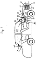
- the first heat exchanger for example, evaporator 11 is disposed in passenger compartment 20 of an automobile, more precisely, in duct assembly 30 which is located under dashboard 21 of the automobile.
- Duct assembly 30 includes duct 31 in which evaporator 11, heater core 32 and a blower (not shown) are disposed in.
- Damper 33 is also disposed in duct 31 and selectively opens and closes outside air inlet opening 34 and passenger compartment air inlet opening 35 by pivoting thereof.
- damper 33 closes passenger compartment air inlet opening 35, that is, opens outside air inlet opening 34. Therefore, the blower is only used for introducing the outside air into duct 31 through outside air inlet opening 34.
- Heater core 32 is used for a heat source of the heating system by utilizing heat of engine 50.
- the second heat exchanger for example, condenser 12 is disposed in engine compartment 60 defined at a front portion of the automobile, more precisely, at in front of radiator 51. Outside air is conducted into engine compartment 60 and is passed through condenser 12 and radiator 51 by operation of condenser fan 13 and radiator fan 52. Accordingly, refrigerant in condenser 12 flowing from the compressor (not shown) is heat exchanged with the outside air, that is, refrigerant is condensed by radiating heat thereof into the outside air.
- outside air inlet mode that is, the situation in which outside air inlet opening 34 is only opened
- the above-mentioned conventional type of automotive air conditioning and heating system can take other two modes one of which is the passenger compartment air inlet mode, another of which is the mixed air inlet mode.
- the passenger compartment air inlet mode means the situation in which passenger compartment air inlet opening 35 is only opened, that is, outside air inlet opening 34 is closed by damper 33 as illustrated by a dashed line in Figure 1.
- the mixed air inlet mode means the situation in which both outside air inlet opening 34 and passenger compartment air inlet opening 35 are maintained to open.
- the air conditioning and heating system when the air conditioning and heating system operates in the outside air inlet mode, the cooled (in the air conditioning stage) or heated (in the heating stage) passenger compartment air, of which amount is equal to the amount of the outside air introduced into the passenger compartment, continuously flowing to the outside automobile with no contribution to heat exchanging of the second heat exchanger. Therefore, efficiency of the air conditioning and heating system is greatly decreased. Accordingly, the air conditioning and heating stages with the outside air inlet mode can not be maintained in a long time when the outside air is hot (in the air conditioning stage) or cold (in the heat stage).
- the automotive air conditioning and heating system includes a heat pump circuit.
- the heat pump circuit is used for the heating system, the first heat exchanger which is disposed in the inside passenger compartment is used as a condenser, and the second heat exchanger which is disposed in the engine compartment is used as a evaporator.
- it is required to maintain effective heat exchanging of the second heat exchanger even when temperature of the outside air is low. Therefore, the mechanism for conducting air to the second heat exchanger is complicated due to providing hot air generated by the engine to the second heat exchanger to heat exchange with thereto.
- the JP-A-57-178913 describes an air-conditioning system for a vehicle operable in a warming and in a cooling mode.
- This document discloses a refrigerating circuit provided with passages and switching doors. These switching doors can be positioned such that either warm air from the outside is cooled and guided into the interior of the car, or cold air from outside is heated and guided to the interior of the car.
- This system requires a complicated mechanism for appropriately positioning the switching doors, and the actual location of the several inlets and outlets required remains obscure.
- the US-A-4,412,425 describes an air conditioning and ventilation system for a motor car which has heat exchangers positioned in the front or the back of the passenger compartment. This document describes a method of reducing the thermal load on the heating and cooling system by mixing different air flows before the air is guided through the heat exchanger.
- Figure 1 is a schematic illustration of a conventional type of an automotive air conditioning and heating system.
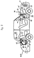
- FIG. 2 is a schematic illustration of an automotive air conditioning and heating system in accordance with one embodiment of the present invention.
- Figure 3 is an partially enlarged schematic illustration of the automotive air conditioning and heating system shown in Figure 2.
- FIG 4 is a block diagram of a heat pump circuit used for the automotive air conditioning and heating system shown in Figure 2.
- FIG. 1 An automotive air conditioning and heating system in accordance with one embodiment is schematically illustrated in Figure 2.
- first heat exchanger 71 is disposed in passenger compartment 20 of an automobile, more precisely, in first duct assembly 70 which is located under dashboard 21 of the automobile.
- First duct assembly 70 includes duct 72 in which first heat exchanger 71, damper 73 and a blower (not shown) are disposed in.
- Damper 73 selectively opens and closes first outside air inlet opening 74 and first passenger compartment air inlet opening 75 by pivoting thereof.
- damper 73 closes first passenger compartment air inlet opening 75, that is, opens first outside air inlet opening 74. Therefore, the blower is only used for introducing the outside air into duct 72 through first outside air inlet opening 74.
- second heat exchanger 81 is disposed in trunk compartment defined at a rear portion of the automobile, more precisely, in second duct assembly 80 which is located behind rear seat 91 of the automobile.
- Second duct assembly 80 includes damper 82, motor fan 83 and casing 84 in which second heat exchanger 81 is disposed in.
- Large opening 84a is formed at a bottom of casing 84 to dispose motor fan 83 therein.
- a top of casing 84 is shaped to have two slanted surfaces, that is, a gable roof.
- Second passenger compartment air inlet opening 85 is formed at the front (to the right in Figure 3) slanted top.
- Second outside air inlet opening 86 is formed at the rear (to the left in Figure 3) slanted top.
- Openings 85a, 86a are formed at rear tray 85b and trunk lid 86b respectively.
- Duct 87 air-tightly links second passenger compartment air inlet opening 85 to opening 85a.
- Duct 88 air-tightly links second outside air inlet opening 86 to opening 86a.
- Ducts 87, 88 and casing 84 are formed in one body.
- Damper 82 selectively opens and closes second passenger compartment air inlet opening 85 and second outside air inlet opening 86 by pivoting thereof. In Figure 3, damper 82 closes second outside air inlet opening 86, that is, opens second passenger compartment air inlet opening 85. Therefore, motor fan 83 is only used for introducing the passenger compartment air into casing 84 through opening 85a and second passenger compartment air inlet opening 85.
- damper 82 closes second passenger compartment air inlet opening 85, that is, opens second outside air inlet opening 86 a illustrated by a dashed line in Figure 3
- motor fan 83 is only used for introducing the outside air into casing 84 through opening 86a and second outside air inlet opening 86.
- a driving device (not shown) is connected to damper 82 to make damper 82 pivot as follows.
- damper 82 closes second outside air inlet opening 86, that is, opens second passenger compartment air inlet opening 85.
- damper 82 closes second passenger compartment air inlet opening 85, that is, opens second outside air inlet opening 86.
- damper 82 opens second passenger compartment air inlet opening 85 to avoid passengers feeling discomfort, for example, an earache of the passengers due to quickly rising or falling pressure in passenger compartment 20.
- the above-mentioned automotive air conditioning and heating system further includes a heat pump circuit diagrammatically illustrated in Figure 4.
- the heat pump circuit includes first heat exchanger 71, second heat exchanger 81, accumulator 100, compressor 101 and four-way valve 102.
- First , second, third and fourth openings 102a, 102b, 102c, and 102d of four-way valve 102 are connected to a discharge port of compressor 101, first heat exchanger 71, second heat exchanger 81 and an inlet port of accumulator 100 respectively.
- An outlet port of accumulator 100 is connected to a suction port of compressor 101.
- First check valve 103 and first expansion valve 104 are disposed between first and second heat exchangers 71, 81 in series.
- Second check valve 106 and second expansion valve 105 are also disposed between first and second heat exchangers 71, 81 in series.
- first check valve 103 and first expansion valve 104 are in parallel with second check valve 106 and second expansion valve 105.
- the dashed arrows indicates the flow of refrigerant as the heat pump circuit is used for the air conditioning system, and the solid arrows indicates the flow of refrigerant as the heat pump is used for heating system.
- the heat pump circuit is used for the air conditioning system to appropriate link each elements of the circuit by using four-way valve 102. Furthermore, damper 73 of first duct assembly 70 closes first passenger compartment air inlet opening 75, that is, opens first outside air inlet opening 74. Simultaneously, damper 82 of second duct assembly 80 closes second outside air inlet opening 86, that is, opens second passenger compartment air inlet opening 85. Accordingly, the outside air is continuously introduced into duct 72 through first outside air inlet opening 74 and is passed through first heat exchanger 71 as an evaporator by operation of the blower.
- the outside air is heat exchanged with the refrigerant in first heat exchanger 71, that is, the refrigerant in first heat exchanger 71 is vaporized by absorbing heat thereto from the outside air.
- the outside air is cooled and blown into passenger compartment 20, thereby passenger compartment 20 being cooled.
- the air in passenger compartment 20 is continuously flowed to casing 84 of second duct assembly 80 via duct 87 and then heat exchanged with the refrigerant in second heat exchanger 81 as a condenser, that is, the refrigerant in second heat exchanger 81 is condensed by radiating heat thereof to the passenger compartment air in casing 84.
- the heat exchanged air is continuously flowed to the outside automobile.
- the heat pump circuit is used for the heating system to appropriate link each elements of circuit by using four-way valve 102. But, dampers 73, 82 are still maintained their position as described above. Accordingly, the outside air is continuously introduced into duct 72 through first outside air inlet opening 74 and is passed through first heat exchanger 71 as a condenser by operation of the blower. Consequently, the outside air is heat exchanged with the refrigerant in first heat exchanger 71, that is, the refrigerant in first heat exchanger 71 is condensed by radiating heat thereof to the outside air in duct 72. In result, the outside air is warmed and blown into passenger compartment 20, thereby passenger compartment 20 being warmed.
- the air in passenger compartment 20 is continuously flowed to the casing 84 or second duct assembly 80 via duct 87 and then heat exchanged with the refrigerant in second heat exchanger 81 as an evaporator, that is, the refrigerant in second heat exchanger 81 is vaporized by absorbing heat thereto from the passenger compartment air. Finally, the heat exchanged air is continuously flowed to the outside automobile.
- the second heat exchanger can maintain effective heat exchanging due to refrigerant in the second heat exchanger heat exchanging with the passenger compartment air which is relatively cooler (in the air conditioning stage) or hotter ( in the heating stage) than the outside air. Therefore, even when the air conditioning and heating system operates in the outside air inlet mode, the air conditioning and heating system operates efficiently, thereby the air conditioning and heating stage with outside air inlet mode being able to be used in a long time. Besides, effective heat exchanging of the second heat exchanger can be maintained with the simple mechanism which conducts air to the second heat exchanger.
- a position of damper 82 of second duct assembly 80 is changed to have only two locations, one of which is to close second passenger compartment air inlet opening 85, another of which is to close second outside air inlet opening 86.
- the damper may be changed its position continuously, that is, the damper may change its position from closing the second outside air inlet opening to closing the second passenger compartment air inlet opening.
- the present invention can be used for an electric automobile as well as an internal-combustion engine type of an automobile.
Claims (6)
- Système de conditionnement d'air automobile pour commander la température d'un habitacle de véhicule automobile, ledit système de conditionnement d'air étant capable de fonctionner dans un mode de refroidissement et de chauffage, et comprenant un circuit de pompe à chaleur, comportant un premier et un second échangeurs de chaleur (71, 81), et
un premier moyen de gaine (72) pour conduire l'air depuis ledit premier échangeur thermique (71) jusgu'audit habitacle, au cours dudit mode de refroidissement et pour conduire l'air depuis ledit premier échangeur thermique (71) jusqu'audit habitacle, au cours dudit mode de chauffage,
caractérisé par
un second moyen de gaine (80) distinct dudit premier moyen de gaine (72) pour conduire l'air depuis ledit habitacle jusqu'audit second échangeur thermique (81), ledit premier moyen de gaine (72) étant à l'avant de l'habitacle et le second moyen de gaine (80) étant situé derrière le siège arrière de l'habitacle. - Système de conditionnement d'air et de chauffage automobile selon la revendication 1, dans lequel
ledit second moyen de gaine (80)
comporte un passage d'arrivée d'air extérieur (88), qui conduit un air extérieur jusqu'audit second échangeur thermique (81)
et un passage conducteur (87) de l'habitacle, qui conduit l'air depuis l'habitacle jusqu'audit second échangeur thermique (81) et
ledit système de conditionnement d'air et de chauffage automobile comprend un moyen (82) pour ouvrir et fermer de façon sélective ledit passage d'arrivée d'air extérieur (88) et ledit passage conducteur d'air (87) de l'habitacle. - Système de conditionnement d'air et de chauffage automobile selon les revendications 1 ou 2, dans lequel un premier échangeur thermique (71) est placé dans ledit habitacle.
- Système de conditionnement d'air et de chauffage automobile selon l'une quelconque des revendications 1 à 3, dans lequel ledit second échangeur thermique (81) est placé dans un compartiment extérieur à l'habitacle.
- Système de conditionnement d'air et de chauffage automobile selon l'une quelconque des revendications 1 à 3, dans lequel ledit second échangeur thermique (81) est placé dans le coffre d'une automobile.
- Système de conditionnement d'air et de chauffage automobile selon l'une des revendications 2 à 5, dans lequel ledit passage d'arrivée d'air extérieur (88) et ledit passage conduisant l'air et l'habitacle (87) sont ouverts et fermés de façon sélective par un amortisseur (82).
Applications Claiming Priority (2)
| Application Number | Priority Date | Filing Date | Title |
|---|---|---|---|
| JP63188394A JPH0238131A (ja) | 1988-07-29 | 1988-07-29 | 車両用空調装置 |
| JP188394/88 | 1988-07-29 |
Publications (3)
| Publication Number | Publication Date |
|---|---|
| EP0356716A1 EP0356716A1 (fr) | 1990-03-07 |
| EP0356716B1 EP0356716B1 (fr) | 1992-12-30 |
| EP0356716B2 true EP0356716B2 (fr) | 1995-10-18 |
Family
ID=16222869
Family Applications (1)
| Application Number | Title | Priority Date | Filing Date |
|---|---|---|---|
| EP89113956A Expired - Lifetime EP0356716B2 (fr) | 1988-07-29 | 1989-07-28 | Système de climatisation de véhicule |
Country Status (7)
| Country | Link |
|---|---|
| US (1) | US4991405A (fr) |
| EP (1) | EP0356716B2 (fr) |
| JP (1) | JPH0238131A (fr) |
| KR (1) | KR900001538A (fr) |
| AU (1) | AU621641B2 (fr) |
| CA (1) | CA1321476C (fr) |
| DE (1) | DE68904144T2 (fr) |
Families Citing this family (31)
| Publication number | Priority date | Publication date | Assignee | Title |
|---|---|---|---|---|
| US5605051A (en) * | 1991-04-26 | 1997-02-25 | Nippondenso Co., Ltd. | Automotive air conditioner having condenser and evaporator provided within air duct |
| US5782102A (en) * | 1992-04-24 | 1998-07-21 | Nippondenso Co., Ltd. | Automotive air conditioner having condenser and evaporator provided within air duct |
| US5299431A (en) * | 1991-04-26 | 1994-04-05 | Nippondenso Co., Ltd. | Automotive air conditioner having condenser and evaporator provided within air duct |
| US5284025A (en) * | 1991-06-17 | 1994-02-08 | Matsushita Electric Industrial Co., Ltd. | Air conditioning apparatus for an electrically-powered motor vehicle |
| JP3267993B2 (ja) * | 1991-11-27 | 2002-03-25 | 本田技研工業株式会社 | 車両用エアコンディショニングシステム |
| FR2697209B1 (fr) * | 1992-10-26 | 1994-12-09 | Valeo Thermique Habitacle | Dispositif et procédé de climatisation d'un véhicule, notamment d'un véhicule électrique. |
| JP3485379B2 (ja) * | 1995-04-06 | 2004-01-13 | サンデン株式会社 | 車両用空気調和装置 |
| JPH08319958A (ja) * | 1995-05-24 | 1996-12-03 | Sanden Corp | スクロール型流体装置 |
| JP3707119B2 (ja) * | 1995-12-25 | 2005-10-19 | 株式会社デンソー | 車両用空調装置 |
| US6608124B1 (en) | 1996-10-03 | 2003-08-19 | Cytec Technology Corp. | Aqueous dispersions |
| US6664326B1 (en) | 1996-10-03 | 2003-12-16 | Cytec Technology Corp. | Aqueous dispersions |
| US5792366A (en) * | 1996-10-03 | 1998-08-11 | Cytec Technology Corp. | Aqueous dispersions |
| US5696228A (en) * | 1996-10-03 | 1997-12-09 | Cytec Technology Corp. | Process for producing substantially dry polymer particles from aqueous dispersions |
| US5843320A (en) * | 1996-10-03 | 1998-12-01 | Cytec Technology Corp. | Aqueous dispersions |
| US6702946B1 (en) | 1996-10-03 | 2004-03-09 | Cytec Technology Corp. | Aqueous dispersions |
| US5919854A (en) * | 1996-10-03 | 1999-07-06 | Cytec Technology Corp. | Process for preparing aqueous dispersions |
| FR2769263B1 (fr) * | 1997-10-08 | 2000-01-07 | Renault | Installation de climatisation et de chauffage pour vehicule automobile |
| US6262168B1 (en) | 1998-03-11 | 2001-07-17 | Cytec Technology Corp. | Aqueous dispersions |
| FR2784943B1 (fr) * | 1998-10-27 | 2000-12-22 | Valeo Climatisation | Installation de chauffage-ventilation de l'habitacle d'un vehicule automobile a extraction selective de l'air |
| JP3600164B2 (ja) * | 2001-02-13 | 2004-12-08 | 三洋電機株式会社 | 冷暖房用車載空気調和機 |
| US6370903B1 (en) | 2001-03-14 | 2002-04-16 | Visteon Global Technologies, Inc. | Heat-pump type air conditioning and heating system for fuel cell vehicles |
| US6971471B2 (en) * | 2001-12-07 | 2005-12-06 | General Motors Corporation | Multi-directional drive |
| DE10203293A1 (de) * | 2002-01-29 | 2003-07-31 | Audi Ag | Klimaanlage |
| JP4312039B2 (ja) * | 2003-12-05 | 2009-08-12 | 昭和電工株式会社 | 超臨界冷媒の冷凍サイクルを有する車両用空調関連技術 |
| DE102005023231A1 (de) * | 2005-05-20 | 2006-11-23 | Bayerische Motoren Werke Ag | Fahrzeug mit einer Klimaanlage und separater Fondkühlung |
| JP2008049782A (ja) * | 2006-08-23 | 2008-03-06 | Calsonic Kansei Corp | 車両用空調装置 |
| US7637031B2 (en) * | 2007-06-26 | 2009-12-29 | Gm Global Technology Operations, Inc. | Evaporator core drying system |
| JP2010023547A (ja) * | 2008-07-15 | 2010-02-04 | Calsonic Kansei Corp | 換気負荷低減装置およびそれを用いた自動車用空調装置 |
| US9168810B2 (en) * | 2012-10-09 | 2015-10-27 | Delphi Technologies, Inc. | Heating and cooling system for occupants of the rear portion of a vehicle |
| US10766333B2 (en) | 2017-03-23 | 2020-09-08 | Ford Global Technologies, Llc | Interchangeable operable duct with blocking component for a driver-only function |
| KR20210030553A (ko) * | 2019-09-09 | 2021-03-18 | 현대자동차주식회사 | 차량용 공조시스템 |
Family Cites Families (17)
| Publication number | Priority date | Publication date | Assignee | Title |
|---|---|---|---|---|
| US2479170A (en) * | 1947-05-07 | 1949-08-16 | Leon L Kuempel | Refrigerating apparatus for vehicles |
| US2922290A (en) * | 1953-11-27 | 1960-01-26 | Thomas W Carraway | Air conditioning system |
| US3817054A (en) * | 1972-12-14 | 1974-06-18 | Heatransfer Corp | Automobile air conditioning system |
| US4051692A (en) * | 1976-10-12 | 1977-10-04 | Paul Ku | Cooling apparatus for automobile passenger compartment |
| JPS55154534A (en) * | 1979-04-12 | 1980-12-02 | Kobe Steel Ltd | Iron ore porous pellet and its manufacture |
| JPS5736164A (ja) * | 1980-08-13 | 1982-02-26 | Masaharu Kuroda | Gijikinzokufunoshoshitasabinaikashokuzainoseizohoho |
| US4494597A (en) * | 1980-11-05 | 1985-01-22 | Nippon Soken, Inc. | Ventilating device for automotive vehicle |
| US4412425A (en) * | 1980-12-09 | 1983-11-01 | Nippon Soken, Inc. | Air conditioning and ventilation system |
| JPS57178913A (en) * | 1981-04-27 | 1982-11-04 | Diesel Kiki Co Ltd | Car air-conditioner |
| JPS5826617A (ja) * | 1981-08-07 | 1983-02-17 | Nippon Denso Co Ltd | カ−エアコン制御装置 |
| JPS6015218A (ja) * | 1983-07-04 | 1985-01-25 | Nippon Denso Co Ltd | 自動車用空気調和装置 |
| JPS6146710A (ja) * | 1984-08-10 | 1986-03-07 | Nippon Denso Co Ltd | 自動車用空気調和装置 |
| JPS6150013U (fr) * | 1984-09-06 | 1986-04-04 | ||
| JPS61205511A (ja) * | 1985-03-08 | 1986-09-11 | Nissan Motor Co Ltd | 自動車用加湿装置 |
| US4688394A (en) * | 1985-03-14 | 1987-08-25 | Technology Un, Ltd. | Automotive heater and air conditioner and process therefor |
| AT391933B (de) * | 1986-08-14 | 1990-12-27 | Altexa Lueftungstechnische Anl | Klima- und lueftungsgeraet zum einbau in eine wand, fenster oder dergleichen |
| US4763564A (en) * | 1987-04-17 | 1988-08-16 | Ford Motor Company | Multiple unit automotive climate control system |
-
1988
- 1988-07-29 JP JP63188394A patent/JPH0238131A/ja active Pending
-
1989
- 1989-07-28 DE DE68904144T patent/DE68904144T2/de not_active Expired - Fee Related
- 1989-07-28 EP EP89113956A patent/EP0356716B2/fr not_active Expired - Lifetime
- 1989-07-28 AU AU39077/89A patent/AU621641B2/en not_active Ceased
- 1989-07-29 KR KR1019890010782A patent/KR900001538A/ko not_active Application Discontinuation
- 1989-07-31 CA CA000607046A patent/CA1321476C/fr not_active Expired - Fee Related
-
1990
- 1990-08-10 US US07/565,898 patent/US4991405A/en not_active Expired - Fee Related
Also Published As
| Publication number | Publication date |
|---|---|
| KR900001538A (ko) | 1990-02-27 |
| CA1321476C (fr) | 1993-08-24 |
| AU3907789A (en) | 1990-02-01 |
| JPH0238131A (ja) | 1990-02-07 |
| US4991405A (en) | 1991-02-12 |
| EP0356716A1 (fr) | 1990-03-07 |
| DE68904144D1 (de) | 1993-02-11 |
| DE68904144T2 (de) | 1996-03-14 |
| AU621641B2 (en) | 1992-03-19 |
| EP0356716B1 (fr) | 1992-12-30 |
Similar Documents
| Publication | Publication Date | Title |
|---|---|---|
| EP0356716B2 (fr) | Système de climatisation de véhicule | |
| KR100755951B1 (ko) | 차량용 시트 공조장치 | |
| US5862677A (en) | Casing unit of air conditioning system and air conditioning system for automobiles using the same | |
| JP4321242B2 (ja) | 車両用空調装置 | |
| JP2000289436A (ja) | 車両用空気調和装置 | |
| US6253841B1 (en) | Vehicular air conditioner with passenger-operated inside/outside air double flow mode | |
| JPH10250342A (ja) | 車両用空調装置 | |
| JP3900592B2 (ja) | 車両用空調装置 | |
| KR101403444B1 (ko) | 차량용 공조장치 | |
| US7191825B2 (en) | Separately air-conditionable vehicle air conditioning unit | |
| JP2001001750A (ja) | 車両用空気調和装置 | |
| JPH11208240A (ja) | 車両用空調装置 | |
| WO2023090084A1 (fr) | Climatiseur de véhicule | |
| JP3494021B2 (ja) | 車両用空調装置 | |
| WO2022270594A1 (fr) | Dispositif de climatisation de véhicule | |
| JP4059136B2 (ja) | 車両用空調装置 | |
| KR100642132B1 (ko) | 자동차 시트 공기조화장치 | |
| JPH11227448A (ja) | 車両用空調装置 | |
| KR100303821B1 (ko) | 자동차용공기조화장치 | |
| KR101183054B1 (ko) | 차량용 시트 공조장치 | |
| JP2000062449A (ja) | ヒートポンプ式自動車用空気調和装置 | |
| JP2023036151A (ja) | 冷却システム | |
| JP3398508B2 (ja) | 自動車用空調装置および自動車用空調方法 | |
| JPH0789331A (ja) | 自動車用空調装置 | |
| JP2002200910A (ja) | 車両用空気調和装置 |
Legal Events
| Date | Code | Title | Description |
|---|---|---|---|
| PUAI | Public reference made under article 153(3) epc to a published international application that has entered the european phase |
Free format text: ORIGINAL CODE: 0009012 |
|
| AK | Designated contracting states |
Kind code of ref document: A1 Designated state(s): DE FR GB IT SE |
|
| 17P | Request for examination filed |
Effective date: 19900313 |
|
| 17Q | First examination report despatched |
Effective date: 19910711 |
|
| ITF | It: translation for a ep patent filed |
Owner name: MARCHI & MITTLER S.R |
|
| GRAA | (expected) grant |
Free format text: ORIGINAL CODE: 0009210 |
|
| AK | Designated contracting states |
Kind code of ref document: B1 Designated state(s): DE FR GB IT SE |
|
| ET | Fr: translation filed | ||
| REF | Corresponds to: |
Ref document number: 68904144 Country of ref document: DE Date of ref document: 19930211 |
|
| PLBI | Opposition filed |
Free format text: ORIGINAL CODE: 0009260 |
|
| 26 | Opposition filed |
Opponent name: BAYERISCHE MOTOREN WERKE AKTIENGESELLSCHAFT Effective date: 19930923 |
|
| EAL | Se: european patent in force in sweden |
Ref document number: 89113956.0 |
|
| PUAH | Patent maintained in amended form |
Free format text: ORIGINAL CODE: 0009272 |
|
| STAA | Information on the status of an ep patent application or granted ep patent |
Free format text: STATUS: PATENT MAINTAINED AS AMENDED |
|
| 27A | Patent maintained in amended form |
Effective date: 19951018 |
|
| AK | Designated contracting states |
Kind code of ref document: B2 Designated state(s): DE FR GB IT SE |
|
| ITF | It: translation for a ep patent filed |
Owner name: MARCHI & MITTLER S.R.L. |
|
| ET3 | Fr: translation filed ** decision concerning opposition | ||
| PGFP | Annual fee paid to national office [announced via postgrant information from national office to epo] |
Ref country code: SE Payment date: 19990707 Year of fee payment: 11 |
|
| PGFP | Annual fee paid to national office [announced via postgrant information from national office to epo] |
Ref country code: GB Payment date: 19990728 Year of fee payment: 11 |
|
| PG25 | Lapsed in a contracting state [announced via postgrant information from national office to epo] |
Ref country code: GB Free format text: LAPSE BECAUSE OF NON-PAYMENT OF DUE FEES Effective date: 20000728 |
|
| PG25 | Lapsed in a contracting state [announced via postgrant information from national office to epo] |
Ref country code: SE Free format text: LAPSE BECAUSE OF NON-PAYMENT OF DUE FEES Effective date: 20000729 |
|
| EUG | Se: european patent has lapsed |
Ref document number: 89113956.0 |
|
| GBPC | Gb: european patent ceased through non-payment of renewal fee |
Effective date: 20000728 |
|
| PGFP | Annual fee paid to national office [announced via postgrant information from national office to epo] |
Ref country code: FR Payment date: 20010712 Year of fee payment: 13 |
|
| PGFP | Annual fee paid to national office [announced via postgrant information from national office to epo] |
Ref country code: DE Payment date: 20010723 Year of fee payment: 13 |
|
| PG25 | Lapsed in a contracting state [announced via postgrant information from national office to epo] |
Ref country code: DE Free format text: LAPSE BECAUSE OF NON-PAYMENT OF DUE FEES Effective date: 20030201 |
|
| PG25 | Lapsed in a contracting state [announced via postgrant information from national office to epo] |
Ref country code: FR Free format text: LAPSE BECAUSE OF NON-PAYMENT OF DUE FEES Effective date: 20030331 |
|
| REG | Reference to a national code |
Ref country code: FR Ref legal event code: ST |
|
| PG25 | Lapsed in a contracting state [announced via postgrant information from national office to epo] |
Ref country code: IT Free format text: LAPSE BECAUSE OF NON-PAYMENT OF DUE FEES;WARNING: LAPSES OF ITALIAN PATENTS WITH EFFECTIVE DATE BEFORE 2007 MAY HAVE OCCURRED AT ANY TIME BEFORE 2007. THE CORRECT EFFECTIVE DATE MAY BE DIFFERENT FROM THE ONE RECORDED. Effective date: 20050728 |