EP0355520B1 - Verfahren zur Wärmebehandlung von Werkstücken - Google Patents
Verfahren zur Wärmebehandlung von Werkstücken Download PDFInfo
- Publication number
- EP0355520B1 EP0355520B1 EP89114350A EP89114350A EP0355520B1 EP 0355520 B1 EP0355520 B1 EP 0355520B1 EP 89114350 A EP89114350 A EP 89114350A EP 89114350 A EP89114350 A EP 89114350A EP 0355520 B1 EP0355520 B1 EP 0355520B1
- Authority
- EP
- European Patent Office
- Prior art keywords
- furnace
- treatment
- gas
- flow
- treatment gas
- Prior art date
- Legal status (The legal status is an assumption and is not a legal conclusion. Google has not performed a legal analysis and makes no representation as to the accuracy of the status listed.)
- Expired - Lifetime
Links
Images

Classifications
-
- C—CHEMISTRY; METALLURGY
- C21—METALLURGY OF IRON
- C21D—MODIFYING THE PHYSICAL STRUCTURE OF FERROUS METALS; GENERAL DEVICES FOR HEAT TREATMENT OF FERROUS OR NON-FERROUS METALS OR ALLOYS; MAKING METAL MALLEABLE, e.g. BY DECARBURISATION OR TEMPERING
- C21D1/00—General methods or devices for heat treatment, e.g. annealing, hardening, quenching or tempering
- C21D1/74—Methods of treatment in inert gas, controlled atmosphere, vacuum or pulverulent material
- C21D1/767—Methods of treatment in inert gas, controlled atmosphere, vacuum or pulverulent material with forced gas circulation; Reheating thereof
-
- C—CHEMISTRY; METALLURGY
- C21—METALLURGY OF IRON
- C21D—MODIFYING THE PHYSICAL STRUCTURE OF FERROUS METALS; GENERAL DEVICES FOR HEAT TREATMENT OF FERROUS OR NON-FERROUS METALS OR ALLOYS; MAKING METAL MALLEABLE, e.g. BY DECARBURISATION OR TEMPERING
- C21D9/00—Heat treatment, e.g. annealing, hardening, quenching or tempering, adapted for particular articles; Furnaces therefor
- C21D9/0056—Furnaces through which the charge is moved in a horizontal straight path
-
- F—MECHANICAL ENGINEERING; LIGHTING; HEATING; WEAPONS; BLASTING
- F27—FURNACES; KILNS; OVENS; RETORTS
- F27B—FURNACES, KILNS, OVENS, OR RETORTS IN GENERAL; OPEN SINTERING OR LIKE APPARATUS
- F27B9/00—Furnaces through which the charge is moved mechanically, e.g. of tunnel type; Similar furnaces in which the charge moves by gravity
- F27B9/30—Details, accessories, or equipment peculiar to furnaces of these types
- F27B9/3005—Details, accessories, or equipment peculiar to furnaces of these types arrangements for circulating gases
-
- F—MECHANICAL ENGINEERING; LIGHTING; HEATING; WEAPONS; BLASTING
- F27—FURNACES; KILNS; OVENS; RETORTS
- F27D—DETAILS OR ACCESSORIES OF FURNACES, KILNS, OVENS, OR RETORTS, IN SO FAR AS THEY ARE OF KINDS OCCURRING IN MORE THAN ONE KIND OF FURNACE
- F27D7/00—Forming, maintaining, or circulating atmospheres in heating chambers
- F27D7/02—Supplying steam, vapour, gases, or liquids
Definitions
- the invention relates to a method for the heat treatment of workpieces under a treatment gas atmosphere in a continuous furnace with an inlet, treatment and cooling zone, in which treatment gas is fed into one or more furnace zones comprising the cooling zone with the usual, low pressure and also a part of the Treatment gas directed in the cooling zone and injected at a higher pressure and thus a certain gas flow is produced in the interior of the furnace.
- heat treatment processes for metallic workpieces under a wide variety of treatment gas atmospheres are known. Examples of these are carburizing, hardening, nitriding and annealing processes e.g. among endogas, exogas, methanol and ammonia cracked gas and gases that are delivered ready to use and can be removed from storage tanks (e.g. nitrogen, hydrogen).
- Heat treatment methods under treatment gas for ceramic workpieces in continuous furnaces are also known, e.g. the burning of such workpieces.
- the treatment gas atmospheres can be divided into protective gas atmospheres and reaction gas atmospheres.
- Protective gases have the task of protecting the materials to be treated from undesired influences during heat treatment, for example from reactions with the oxygen, carbon dioxide or water vapor contained in the air, while desired reactions with the material to be treated are brought about in reaction gas atmospheres.
- the treatment gases are generally introduced into the heat treatment devices or furnaces at a plurality of points with a pressure slightly above atmospheric pressure (approximately between 0.01 and 0.2 mbar) and a low flow rate.
- the feed quantities and the feed points are selected so that a treatment gas atmosphere which is of sufficient quality for the respective treatment is established throughout the device and leak losses are compensated for.
- there is no deliberately chosen preferred flow direction of the introduced treatment gas but rather a flow results that depends on the particular furnace design, the flow essentially from one or more feed points to one or more main outflow points, e.g. the furnace entrance and exit.
- a heat treatment method for a continuous furnace is known from EP-B1 75 438, for example, in which curtains or flap-like closures at the furnace outlet and a suitable introduction rate of the treatment gas into the various furnace regions and in particular also in the cooling zone cause a flow in the direction of the furnace inlet becomes.
- a portion of the treatment gas to be supplied to the cooling zone be introduced into it in an appropriately directed manner, and thus to support the desired flow formation.
- EP-B1 75 438 using a series of measures, a very specific gas flow pattern directed towards the furnace entrance is set in a continuous furnace, which primarily serves to reduce the amount of treatment gas required for a heat treatment.
- This object is achieved with a method as described at the outset, in addition to which the gas which is blown in in the direction of the cooling zone is blown in at the higher pressure of 1 to 20 bar gauge pressure in the form of one or more blowing jets, and the amount of gas blown in is 5 to 35% of that the low pressure supplied to the furnace, makes up the amount of gas and - solely because of this - a treatment gas flow is produced in the entire furnace either in or against the direction of flow of the workpieces to be treated.
- the proportion of injection of the treatment gas which is blown in at the higher pressure which is preferably only 5 to 20% of the amount of gas supplied at the low pressure, is blown in at an excess pressure of 2 to 6 bar.
- This procedure can be carried out manually or automatically with an electronic control unit.
- a blowing device particularly suitable for carrying out the invention essentially consists of a straight, elongated tube, one end of which is closed except for one or more gas outlet openings with the desired orientation and which can be connected to a treatment gas supply via the other end.
- a straight, elongated tube in contrast to curved or diameter-varying shapes, can simply be inserted into an opening in the furnace wall and mounted therein.
- the tubular injection device is designed to be rotatable about its longitudinal axis at least by 180 ° at least in the region of the gas outlet opening (s).
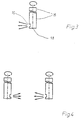
- FIG. 3 shows a blowing device suitable for carrying out the invention. It essentially consists of a straight tube 15 which is closed on one side and in which at the closed end there is a gas outlet opening 16 with an orientation perpendicular to the tube axis.
- This blowing device can be easily installed through an opening in the furnace wall, for example as shown below in connection with FIGS. 1 and 2.
- FIG. 1 and 2 each show a continuous furnace 1 with inlet zone 2, treatment zone 3, cooling zone 4, furnace inlet 5 and furnace outlet 6.
- Treatment gas is fed to the continuous furnace 1 via the lines 11, 12, 13, 14 and the blowing devices 7, 8, the blowing devices 7 or 7 and 8 being connected to a treatment gas supply via a valve 9 or a three-way valve 10.
- an arrow 17 indicates the direction in which workpieces to be treated cross the continuous furnace.
- treatment gas would be supplied to the furnace via lines 11, 12, 13, 14 in an amount such that an atmosphere of the desired quality would arise in all furnace zones 2, 3, 4. Overall, this would result in a furnace gas flow such that protective or reaction gas introduced into the treatment zone would flow off both to the furnace inlet and to the furnace outlet.
- the shielding gas quantities introduced into the inlet and outlet zones would also leave the furnace through the furnace opening nearby. In this way, one would essentially obtain a two-part flow from the middle of the furnace to the furnace inlet and outlet.
- part of the treatment gas is blown into the cooling zone of the furnace system with the aid of blowing device 7.
- the blowing device 7 is arranged approximately in the central part of the cooling zone 4 and, in the case shown, is aligned against the direction of flow of the objects to be treated.
- Treatment gas is also supplied on both sides of the blowing device 7 with supply lines 13, 14 to the cooling zone 4. Due to the directed blowing with high pressure, i.e. pressure between 1 and 20 bar, preferably between 2 and 6 bar, the gas surrounding the blowing nozzle is entrained and so there is initially a flow in the cooling zone which flows to the treatment zone 3, whereby on Oven outlet 6 even a small proportion of the outside air is sucked in.
- this flow orientation results in a type of stowage area, in which treatment gas flowing out of the treatment zone and flowing with the flow from the cooling zone 4 runs against one another. Overall, this essentially prevents treatment gas from flowing out of the treatment zone 3 into the cooling zone 4. This has the result that excess treatment gas flows out of the treatment zone 3 essentially towards the inlet zone 2, which in turn creates a gas flow there opposite to the direction of flow towards the furnace inlet 5.
- These flow conditions are indicated by the arrows shown in Figure 1.
- a furnace gas flow similar to that described below in connection with FIG. 2, can be generated in the direction of flow of the objects to be treated.
- FIG. 2 shows a continuous furnace 1 with two blowing devices 7, 8 which can be switched alternately via the three-way valve 10 and only one further feed line 14 for treatment gas into the cooling zone 4.
- the blowing device 7 If the blowing device 7 is switched on, a furnace gas flow against the direction of flow is generated in a manner similar to that just described. If a furnace train is to be generated in the direction of flow, treatment gas is blown in the direction of the furnace exit into the cooling zone with the blowing device 8 arranged in the first third of the cooling zone 4 following the treatment zone 3, which in turn applies the entire atmosphere in the cooling zone to this flow direction and wherein in addition - with this arrangement of the injection nozzle 8 - treatment gas is already sucked out of the treatment zone 3.
- the aim with regard to heat treatments under treatment gas is to deliberately avoid the inevitable ingress of air components into the furnace - which is known to be reduced by a high throughput of treatment gas through the furnace to be approved on one side on the side that is harmless to the heat treatment material. This is achieved through the directional flow.
- significant savings in treatment gas are possible compared to the conventional process, since the furnace atmosphere can still be produced in all furnace areas with the necessary purity using a smaller amount of gas. This is an essential effect of the method according to the invention.
- the amount of the injected treatment gas is between 3 and 35%, preferably between 5 and 20%, of the amount that is supplied to the heat treatment device in a conventional manner with the lower pressure.
- An example of a treatment in which the method according to the invention can be used with a furnace train directed against the direction of flow is the annealing of nickel-copper alloys, because the penetration of air, particularly oxygen, into the materials due to the high corrosion resistance of these materials the cooling zone does not deteriorate the annealing result.
- the annealing of steel should be mentioned, in which it is possible to work with a furnace train directed in the direction of travel, since a certain degree of contamination from the air, in particular based on carbon dioxide, is tolerable for steel in the entrance area of the treatment furnace.
- a favorable, practical embodiment of the invention is obtained by two parallel-arranged blowing devices of the type described above, partially aligned with respect to their blow-out direction, as shown in FIG.
- injection devices which are rotatable about their axis
- an oblique injection of treatment gas directed at different angles to the direction of flow is possible.
- the method according to the invention can also be used to influence a flow that occurs from the beginning in a treatment furnace.
- a flow that occurs from the beginning in a treatment furnace For example, in an oven system due to unfavorable drafts in the hall surrounding the oven system, the use of the method according to the invention, even in a controlled version with an oven draft sensor and a correspondingly adjustable injection pressure, is a suitable way of generating a desired oven draft.
- the method according to the invention can be used in many heat treatments in an economically and / or technically advantageous manner.
Description
- Die Erfindung bezieht sich auf ein Verfahren zur Wärmebehandlung von Werkstücken unter Behandlungsgasatmosphäre in einem Durchlaufofen mit Einlauf-, Behandlungs- und Kühlzone, bei dem Behandlungsgas in eine oder mehrere, die Kühlzone umfassende, Ofenzonen mit üblichem, niedrigem Druck zugeführt wird und außerdem ein Teil des Behandlungsgases in der Kühlzone gerichtet und mit einem höheren Druck eingeblasen und damit in Verbindung eine bestimmte Gasströmung im Ofeninnenraum hergestellt wird.
- Es sind beispielsweise vielerlei Wärmebehandlungsverfahren für metallische Werkstücke unter verschiedensten Behandlungsgasatmosphären bekannt. Beispiele hierfür sind Aufkohl-, Härte-, Nitrier- und Glühverfahren z.B. unter Endogas, Exogas, Methanol- und Ammoniakspaltgas und Gasen, die verbrauchsfertig geliefert aus Speicherbehältern entnehmbar sind (z.B. Stickstoff, Wasserstoff). Ebenso sind Wärmebehandlungsverfahren unter Behandlungsgas für keramische Werkstücke in Durchlauföfen bekannt, z.B. das Brennen derartiger Werkstücke.
- Die Behandlungsgasatmosphären lassen sich dabei in Schutzgasatmosphären und Reaktionsgasatmosphären einteilen. Schutzgase haben die Aufgabe, die zu behandelnden Werkstoffe bei der Wärmebehandlung vor unerwünschten Einflüssen zu schützen, z.B. vor Reaktionen mit dem in der Luft enthaltenen Sauerstoff, Kohlendioxid oder Wasserdampf, während mit Reaktionsgasatmosphären gewünschte Reaktionen mit dem zu behandelnden Werkstoff herbeigeführt werden.
- Die Behandlungsgase werden bei den heute bekannten Verfahren in der Regel an mehreren Stellen mit geringfügig über dem Atmosphärendruck liegenden Druck (etwa zwischen 0.01 und 0.2 mbar) und niedriger Strömungsgeschwindigkeit in die Wärmebehandlungseinrichtungen bzw. -öfen eingeführt. Dabei werden die Einspeisemengen und die Einspeisestellen so gewählt, daß sich überall in der Einrichtung eine qualitativ für die jeweilige Behandlung ausreichende Behandlungsgasatmosphäre einstellt und Leckverluste ausgeglichen werden. Im Regelfall besteht dabei keine absichtlich gewählte Vorzugsstromrichtung des eingeleiteten Behandlungsgases, sondern es ergibt sich ein Strom, der von der jeweiligen Ofenausgestaltung abhängt, wobei der Strom im wesentlichen von einer oder mehreren Einspeisestellen zu einer oder mehreren Hauptausflußstellen, z.B. dem Ofenein- und -ausgang, verläuft.
- Andererseits ist z.B. aus der EP-B1 75 438 ein Wärmebehandlungsverfahren für einen Durchlaufofen bekannt, bei dem durch vorhang- oder klappenartige Verschlüsse am Ofenausgang und eine geeignete Einführungsrate des Behandlungsgases in die verschiedenen Ofenbereiche und insbesondere auch in den Kühlzone eine Strömung in Richtung des Ofeneingangs bewirkt wird. In ausgeführten Gestaltungsvarianten dieses Verfahrens wird zudem angeregt, einen Anteil des der Kühlzone zuzuführenden Behandlungsgases mit einem Injektor entsprechend gerichtet in diese einzuführen, und so die gewünschte Strömungsausbildung zu unterstützen. Gemäß der EP-B1 75 438 wird also unter Aufwendung einer Reihe von Maßnahmen ein ganz spezifisches, zum Ofeneintritt hin gerichtetes Gasströmungsmuster in einem Durchlaufofen eingestellt, das vor allem dazu dient, die notwendige Menge an Behandlungsgas für eine Wärmebehandlung zu reduzieren.
- Grundsätzlich ist es aber wünschenswert, die Gasströmung in einem Durchlaufofen, je nach Anforderung bei der durchzuführenden Behandlung, beeinflussen oder bestimmen zu können. Darin besteht auch die Aufgabenstellung der vorliegenden Erfindung.
- Diese Aufgabe wird mit einem wie eingangs beschriebenen Verfahren gelöst, wobei zudem das in der Kühlzone gerichtet eingeblasene Gas mit dem höheren Druck von 1 bis 20 bar Überdruck in Form eines oder mehrerer Blasstrahlen eingeblasen wird und die so eingeblasene Gasmenge 5 bis 35 % der, mit dem niedrigen Druck dem Ofen zugeführten, Gasmenge ausmacht und - allein dadurch - eine Behandlungsgasströmung im gesamten Ofen wahlweise in oder gegen die Durchlaufrichtung der zu behandelnden Werkstücke hergestellt wird.
- In besonders vorteilhafter Weise wird beim erfindungsgemäßen Verfahren der Einblas-Anteil des mit dem höheren Druck eingeblasenen Behandlungsgases, der vorzugsweise nur 5 bis 20 % der mit dem niedrigen Druck zugeführten Gasmenge beträgt, mit einem Überdruck von 2 bis 6 bar eingeblasen.
- Diese Drucke sind einerseits problemlos verfügbar und andrerseits zur Erzeugung der gewünschten Strömungen geeignet.
- Besonders vorteilhaft wird das erfindungsgemäße Verfahren derart ausgestaltet, daß die Behandlungsgasströmung (= Ofenzug) mit einem Ofenzugsensor gemessen und der Einblasdruck des Behandlungsgases entsprechend diesem Meßwert und dem gewünschten Ofenzug eingestellt wird. Diese Vorgehensweise kann manuell oder in automtischer Weise mit einer elektronischen Regeleinheit ausgeführt werden.
- Eine zur Ausführung der Erfindung besonders geeignete Einblasvorrichtung besteht im wesentlichen aus einer geraden, länglichen Röhre, deren eines Ende bis auf eine oder mehrere Gasauslaßöffnungen mit gewünschter Ausrichtung verschlossen ist und die über das andere Ende mit einer Behandlungsgasversorgung verbindbar ist.
- Eine gerade, längliche Röhre kann im Gegensatz zu krummen oder im Durchmesser variierenden Formen einfach in eine in der Ofenwand angebrachte Öffnung eingeführt und darin montiert werden.
- In einer vorteilhaften Ausgestaltung ist die rohrartige Einblasvorrichtung zumindest im Bereich der Gasauslaßöffnung(en) um ihre Längsachse mindestens um 180 ° drehbar ausgestaltet. Dadurch kann mit einer Einblasvorrichtung eine Strömung in oder eine Strömung gegen die Durchlaufrichtung in einem Durchlaufofen erzeugt werden.
- Anhand der folgenden schematischen Zeichnungen soll das erfindungsgemäße Verfahren mit dazugehörigen Vorrichtungen beispielhaft näher erläutert und eine geeignete Einblasvorrichtung genauer beschrieben werden.
- Es zeigen:
- Figur 1
- einen Durchlaufofen mit einer in der Kühlzone angebrachten Einblasvorrichtung,
- Figur 2
- einen Durchlaufofen mit zwei Einblasvorrichtungen in der Kühlzone,
- Figur 3
- eine Einblasvorrichtung,
- Figur 4:
- eine günstige Anordnung zweier drehbarer Einblasvorrichtungen.
- Figur 3 zeigt eine zur Durchführung der Erfindung geeignete Einblasvorrichtung. Sie besteht im wesentlichen aus einer geraden, einseitig verschlossenen Röhre 15, bei der sich am verschlossenen Ende am Umfang eine Gasauslaß-Öffnung 16 mit zur Rohrachse senkrechter Ausrichtung befindet. Diese Einblasvorrichtung kann durch eine Öffnung in der Ofenwand einfach installiert werden, beispielsweise wie im folgenden in Zusammenhang mit Figuren 1 und 2 gezeigt.
- In den Figuren 1 und 2 ist jeweils ein Durchaufofen 1 mit Einlaufzone 2, Behandlungszone 3, Kühlzone 4, Ofeneingang 5 und Ofenausgang 6 gezeigt. Behandlungsgas wird dem Durchlaufofen 1 über die Leitungen 11, 12, 13, 14 und die Einblasvorrichtungen 7, 8 zugeführt, wobei die Einblasvorrichtungen 7 bzw. 7 und 8 über ein Ventil 9 bzw. über ein Dreiwegeventil 10 mit einer Behandlungsgasversorgung verbunden sind. Ein Pfeil 17 gibt schließlich die Richtung an, in der zu behandelnde Werkstücke den Durchlaufofen durchqueren.
- Würde der gezeigte Durchlaufofen 1 in konventioneller Weise betrieben, so würde dem Ofen über die Leitungen 11, 12, 13, 14 Behandlungsgas in einer Menge zugeführt, daß sich in allen Ofenzonen 2, 3, 4 eine Atmosphäre gewünschter Qualität einstellen würde. Insgesamt ergäbe sich dabei etwa eine Ofengasströmung derart, daß in die Behandlungszone eingeführtes Schutz- oder auch Reaktionsgas sowohl zum Ofeneingang als auch zum Ofenausgang hin abfließen würde. Die in die Einlaufzone und Auslaufzone eingeführten Schutzgasmengen würden den Ofen dabei ebenfalls über die jeweils in der Nähe liegende Ofenöffnung verlassen. Man erhielte so also insgesamt im wesentlichen eine zweigeteilte Strömung von der Ofenmitte hin zum Ofenein- und -ausgang.
- Erfindungsgemäß dagegen, wird, wie beispielsweise in Figur 1 gezeigt, ein Teil des Behandlungsgases mit Hilfe von Einblasvorrichtung 7 in die Kühlzone der Ofenanlage gerichtet eingeblasen. Die Einblasvorrichtung 7 ist etwa im mittleren Teil der Kühlzone 4 angeordnet und im gezeichneten Fall gegen die Durchlaufrichtung der zu behandelnden Gegenstände ausgerichtet. Behandlungsgas wird außerdem beidseitig der Einblasvorrichtung 7 mit Zufuhrleitungen 13, 14 der Kühlzone 4 zugeführt. Durch das gerichtete Einblasen mit hohem Druck, also Drucken zwischen 1 und 20 bar, vorzugsweise zwischen 2 und 6 bar, wird das die Einblasdüse umgebende Gas mitgerissen und es ergibt sich so zunächst in der Kühlzone eine Strömung die zur Behandlungszone 3 hin fließt, wobei am Ofenausgang 6 sogar ein geringer Anteil der außen anliegenden Luft eingesaugt wird. Zur Behandlungszone hin ergibt sich durch diese Strömungsausrichtung eine Art Staubereich, in dem aus der Behandlungszone ausfließendes und mit der Strömung aus der Kühlzone 4 fließendes Behandlungsgas gegeneinander anlaufen. Ingesamt wird dadurch im wesentlichen ein Ausfließen von Behandlungsgas aus der Behandlungszone 3 in die Kühlzone 4 verhindert. Dies hat zur Folge, daß Überschußbehandlungsgas aus der Behandlungszone 3 im wesentlichen zur Einlaufzone 2 hin abfließt, wodurch dort wiederum eine Gasströmung entgegengesetzt zur Durchlaufrichtung hin zum Ofeneingang 5 entsteht. Diese Strömungsverhältnisse sind durch die in Figur 1 dargestellten Pfeile angedeutet.
- Durch Drehen der Einblasvorrichtung um 180 ° kann dagegen eine Ofengasströmung, ähnlich wie im folgenden in Zusammenhang mit Figur 2 beschrieben, in Durchlaufrichtung der zu behandelnden Gegenstände erzeugt werden.
- In Figur 2 ist ein Durchlaufofen 1 mit zwei über das Dreiwegeventil 10 wechselweise schaltbaren Einblasvorrichtungen 7, 8 und nur einer weiteren Zufuhrleitung 14 für Behandlungsgas in die Kühlzone 4 dargestellt. Ist die Einblasvorrichtung 7 ein geschaltet, wird eine Ofengasströmung gegen die Durchlaufrichtung ähnlich wie eben beschrieben erzeugt. Soll ein Ofenzug in Durchlaufrichtung erzeugt werden, wird mit der im ersten Drittel der Kühlzone 4 im Anschluß an die Behandlungszone 3 angeordneten Einblasvorrichtung 8 Behandlungsgas in Richtung des Ofenausganges in die Kühlzone eingeblasen, wodurch wiederum die gesamte Atmosphäre in der Kühlzone mit dieser Strömungsrichtung beaufschlagt wird und wobei darüber hinaus - bei dieser Anordnung der Einblasdüse 8 - bereits Behandlungsgas aus der Behandlungszone 3 angesaugt wird. Daraus ergibt sich ein bevorzugtes Ausströmen des überschüssigen Behandlungsgases aus der Behandlungszone in die Kühlzone, während praktisch kein Behandlungsgas aus der Behandlungszone in die Einlaufzone 2 fließt und sogar das der Einlaufzone zugeführte Behandlungsgas eine überwiegende Strömung in die Behandlungszone hinein erhält. Wiederum sind die Strömungsverhältnisse in dieser Betriebssituation in der Figur durch Pfeile angedeutet.
- Insgesamt ist festzustellen, daß je nach Ausrichtung der Einblasvorrichtung eine in die entsprechende Richtung stabile Ofenströmung erzeugt werden kann. Zielrichtung dabei im Hinblick auf Wärmebehandlungen unter Behandlungsgas ist, den grundsätzlich nicht zu vermeidenden Einbruch von Luftbestandteilen in den Ofen - der bekanntermaßen durch einen hohen Durchsatz von Behandlungsgas durch den Ofen verringert werden kann - absichtlich einseitig auf der für das Wärmebehandlungsgut unschädlicheren Seite zuzulassen. Dies wird durch die gerichtete Strömung erreicht. Damit einhergehend sind wesentliche Einsparungen an Behandlungsgas im Vergleich zum konventionellen Verfahren möglich, da mit geringerer Gasmenge trotzdem in allen Ofenbereichen die Ofenatmosphäre in notwendiger Reinheit hergestellt werden kann. Dies ist einen wesentlicher Effekt des erfindungsgemäßen Verfahrens. Die Menge des eingeblasenen Behandlungsgases liegt dabei zwischen 3 und 35 %, vorzugsweise zwischen 5 und 20 %, der Menge, die der Wärmebehandlungseinrichtung auf konventionelle Art mit dem niedrigeren Druck zugeführt wird.
- Als Beispiel für eine Behandlung, bei dem das erfindungsgemäße Verfahren mit einem gegen die Durchlaufrichtung gerichteten Ofenzug angewendet werden kann, ist das Glühen von Nickel-Kupfer-Legierungen zu nennen, da wegen der hohen Korrosionsbeständigkeit dieser Werkstoffe das Eindringen von Luftanteilen, insbesondere Sauerstoff, in die Kühlzone zu keiner Verschlechterung des Glühergebnisses führt.
- Als weiteres Beispiel sei das Glühen von Stahl erwähnt, bei dem mit einem in Durchlaufrichtung gerichteten Ofenzug gearbeitet werden kann, da für Stahl im Eingangsbereich des Behandlungsofen ein gewisses Maß an Verunreinigungen aus der Luft, insbesondere bezogen auf Kohlendioxid, tolerierbar ist.
- Eine günstige, praktische Ausgestaltung der Erfindung erhält man durch zwei parallel angeordnete, bezüglich ihrer Ausblasrichtung teilweise gegeneinander ausgerichtete Einblasvorrichtungen der obenbeschriebenen Bauart, wie sie in Figur 4 gezeigt ist. Mit dieser Anordnung von Einblasvorrichtungen, die um ihre Achse drehbar sind, ist ein schräges, in verschiedenen Winkeln zur Durchlaufrichtung gerichtetes Einblasen von Behandlungsgas möglich. Durch geeignet koordinierte, insbesondere in gleicher Schräge bezüglich der Durchlaufrichtung ausgerichtete Orientierung der beiden Einblasvorrichtungen sind so ebenfalls Strömungen in oder gegen die Durchlaufrichtung in sehr effizienter Weise erzeugbar.
- Mit dem erfindungsgemäßen Verfahren kann schließlich auch Einfluß auf eine in einem Behandlungsofen von vorne herein auftretende Strömung genommen werden. Herrscht z.B. in einer Ofenanlage aufgrund ungünstiger Luftzugverhältnisse in der die Ofenanlage umgebenden Halle eine unerwünschte Strömung, so ist die Anwendung des erfindungsgemäßen Verfahrens möglicherweise sogar in geregelter Version mit Ofenzugsensor und entsprechend regelbarem Einblasdruck eine geeignete Möglichkeit, einen gewünschten Ofenzug zu erzeugen.
- Zusammenfassend kann festgestellt werden, daß das erfindungsgemäße Verfahren bei vielen Wärmebehandlungen in ökonomisch und/oder produktionstechnisch vorteilhafter Weise eingesetzt werden kann.
Claims (5)
- Verfahren zur Wärmebehandlung von Werkstücken unter Behandlungsgasatmosphäre in einem Durchlaufofen mit Einlauf-, Behandlungs- und Kühlzone,
bei dem Behandlungsgas in eine oder mehrere, die Kühlzone umfassende, Ofenzonen mit üblichem, niedrigem Druck zugeführt wird und außerdem ein Teil des Behandlungsgases in der Kühlzone gerichtet und mit einem höheren Druck eingeblasen und damit in Verbindung eine bestimmte Gasströmung im Ofeninnenraum hergestellt wird, wobei die in der Kühlzone gerichtet und mit dem höheren Druck von 1 bis 20 bar Überdruck in Form eines oder mehrerer Blasstrahlen eingeblasene Gasmenge 5 bis 35 % der, mit dem niedrigen Druck dem Ofen zugeführten, Gasmenge ausmacht und allein dadurch eine Behandlungsgasströmung im gesamten Ofen wahlweise in oder gegen die Durchlaufrichtung der zu behandelnden Werkstücke hergestellt wird. - Verfahren nach Anspruch 1, dadurch gekennzeichnet, daß 5 bis 20 % der mit dem niedrigen Druck zugeführten Gasmenge mit dem höheren Druck eingeblasen wird.
- Verfahren nach einem der Ansprüche 1 oder 2, dadurch gekennzeichnet, daß der Anteil des mit dem höheren Druck eingeblasenen Behandlungsgases mit einem Überdruck von 2 bis 6 bar eingeblasen wird.
- Verfahren nach einem der Ansprüche 1 bis 3, dadurch gekennzeichnet, daß die Behandlungsgasströmung mit einem Ofenzugsensor gemessen und der Einblasdruck entsprechend diesem Meßwert und dem gewünschten Ofenzug eingestellt wird.
- Verfahren nach einem der Ansprüche 1 bis 4, dadurch gekennnzeichnet, daß das Einblas-Behandlungsgas im Falle mehrerer, unabhängiger Blasstrahlen zueinander koordiniert, jedoch schräg zur Durchlaufrichtung eingeblasen wird und so die gewünschte Gasströmung in oder gegen die Durchlaufrichtung erzeugt wird.
Priority Applications (1)
| Application Number | Priority Date | Filing Date | Title |
|---|---|---|---|
| AT89114350T ATE104360T1 (de) | 1988-08-18 | 1989-08-03 | Verfahren zur waermebehandlung von werkstuecken. |
Applications Claiming Priority (2)
| Application Number | Priority Date | Filing Date | Title |
|---|---|---|---|
| DE3828134 | 1988-08-18 | ||
| DE3828134A DE3828134A1 (de) | 1988-08-18 | 1988-08-18 | Verfahren zur waermebehandlung von werkstuecken |
Publications (3)
| Publication Number | Publication Date |
|---|---|
| EP0355520A2 EP0355520A2 (de) | 1990-02-28 |
| EP0355520A3 EP0355520A3 (en) | 1990-04-18 |
| EP0355520B1 true EP0355520B1 (de) | 1994-04-13 |
Family
ID=6361156
Family Applications (1)
| Application Number | Title | Priority Date | Filing Date |
|---|---|---|---|
| EP89114350A Expired - Lifetime EP0355520B1 (de) | 1988-08-18 | 1989-08-03 | Verfahren zur Wärmebehandlung von Werkstücken |
Country Status (4)
| Country | Link |
|---|---|
| EP (1) | EP0355520B1 (de) |
| AT (1) | ATE104360T1 (de) |
| DE (2) | DE3828134A1 (de) |
| ZA (1) | ZA896284B (de) |
Families Citing this family (6)
| Publication number | Priority date | Publication date | Assignee | Title |
|---|---|---|---|---|
| DE4121277C2 (de) * | 1991-06-27 | 2000-08-03 | Ald Vacuum Techn Ag | Vorrichtung und Verfahren zur selbsttätigen Überwachung der Betriebssicherheit und zur Steuerung des Prozeßablaufs bei einem Vakuum-Wärmebehandlungsofen |
| ATE270714T1 (de) * | 1999-08-18 | 2004-07-15 | Patherm Sa | Vorrichtung zum durchlaufwärmebehandeln von metallischen werkstücken, einzeln oder gruppenweise |
| DE10347312B3 (de) * | 2003-10-08 | 2005-04-14 | Air Liquide Deutschland Gmbh | Verfahren zur Wärmebehandlung von Eisenwerkstoffen |
| DE102006015739A1 (de) * | 2006-04-04 | 2007-10-11 | Linde Ag | Verfahren zur Wärmebehandlung |
| US7955450B2 (en) | 2006-04-04 | 2011-06-07 | Linde Aktiengesellschaft | Method for heat treatment |
| EP1842931B1 (de) * | 2006-04-04 | 2014-02-19 | Linde AG | Verfahren zur Wärmebehandlung |
Family Cites Families (8)
| Publication number | Priority date | Publication date | Assignee | Title |
|---|---|---|---|---|
| DE617319C (de) * | 1931-05-02 | 1935-08-16 | Benno Schilde Maschb Akt Ges | Verfahren und Einrichtung zum Blankgluehen |
| US3415503A (en) * | 1967-08-18 | 1968-12-10 | Btu Eng Corp | Conditioned atmosphere furnace muffle |
| DE2601658C3 (de) * | 1976-01-17 | 1978-11-30 | Fa. J.F. Mahler, 7300 Esslingen | Kühlvorrichtung für einen an der Ein- und Auslaßseite offenen Durchlaufofen zum Wärmebehandeln von Werkstücken |
| DE2844843C2 (de) * | 1978-10-14 | 1985-09-12 | Ipsen Industries International Gmbh, 4190 Kleve | Industrieofen zur Wärmebehandlung metallischer Werkstücke |
| JPS57192215A (en) * | 1981-05-21 | 1982-11-26 | Ishikawajima Harima Heavy Ind Co Ltd | Metal-heating oven |
| EP0075438B1 (de) * | 1981-09-19 | 1987-12-16 | BOC Limited | Wärmebehandlung von Metallen |
| DE3208574A1 (de) * | 1982-03-10 | 1983-09-22 | Schmetz Industrieofenbau und Vakuum-Hartlöttechnik KG, 5750 Menden | "vakuum-schachtofen" |
| DE3736501C1 (de) * | 1987-10-28 | 1988-06-09 | Degussa | Verfahren zur Waermebehandlung metallischer Werkstuecke |
-
1988
- 1988-08-18 DE DE3828134A patent/DE3828134A1/de not_active Ceased
-
1989
- 1989-08-03 DE DE58907441T patent/DE58907441D1/de not_active Expired - Fee Related
- 1989-08-03 EP EP89114350A patent/EP0355520B1/de not_active Expired - Lifetime
- 1989-08-03 AT AT89114350T patent/ATE104360T1/de not_active IP Right Cessation
- 1989-08-17 ZA ZA896284A patent/ZA896284B/xx unknown
Also Published As
| Publication number | Publication date |
|---|---|
| EP0355520A3 (en) | 1990-04-18 |
| EP0355520A2 (de) | 1990-02-28 |
| DE3828134A1 (de) | 1990-02-22 |
| ZA896284B (en) | 1990-04-25 |
| ATE104360T1 (de) | 1994-04-15 |
| DE58907441D1 (de) | 1994-05-19 |
Similar Documents
| Publication | Publication Date | Title |
|---|---|---|
| EP0317706B1 (de) | Rauchgaskanal zur Behandlung eines Rauchgases | |
| EP0355520B1 (de) | Verfahren zur Wärmebehandlung von Werkstücken | |
| DE2165020A1 (de) | Verfahren und Vorrichtung zum kontinuierlichen Glühen strangförmigen Guts | |
| DE3503089C2 (de) | ||
| DE2601658A1 (de) | Kuehlvorrichtung fuer einen durchlaufofen | |
| DE1483378B1 (de) | Verfahren zum Fuehren von Metallbaendern in Durchlaufoefen od.dgl. | |
| WO1999054511A1 (de) | Variabel einsetzbare kombilanze mit verschiebbaren brenner- und blaslanzenkörpern | |
| DE3908027C2 (de) | Verfahren und Vorrichtung zum Glühen metallischer Gegenstände | |
| DE3234863C2 (de) | Verfahren und Vorrichtung zum Blankglühen von metallischen Werkstücken mit Stickstoff als Schutzgas | |
| EP0430144B1 (de) | Verfahren und Vorrichtung zur Minderung der Stickoxid-Konzentration im Abgasstrom von Verbrennungsprozessen | |
| CH615948A5 (de) | ||
| DE3039154C2 (de) | Vorrichtung zur direkten Wärmebehandlung von warmgewalztem Stahldraht | |
| DE3819803C1 (de) | ||
| EP3638823B1 (de) | Rüssel für eine schmelztauchbeschichtungsanlage sowie verfahren für dessen betrieb | |
| DE4317733A1 (de) | Verfahren zum Einstellen der Zufuhr eines einem Schmelzofen zuzuführenden Reaktionsgases und ein Vielzweckbrenner zur Durchführung des Verfahrens | |
| DD157576A5 (de) | Verfahren und vorrichtung zum zuenden eines aus einem festbrennstoff und einem sintergut bestehenden sintergemisches | |
| EP3638822B1 (de) | Vorrichtung und verfahren zur separierung von gasatmosphären | |
| DE2718748C3 (de) | Verfahren und Vorrichtung zum Trennen eisenhaltiger metallurgischer Erzeugnisse großer Dicke | |
| DE19634693C2 (de) | Verfahren und Vorrichtung zur Reduzierung bzw. zur Vermeidung des Luft- bzw. Gasaustausches im Bereich temperaturmäßig unterschiedlicher Zonen | |
| DE2605826A1 (de) | Verfahren und vorrichtung zum patentieren von stahldraehten | |
| DE2546866A1 (de) | Mehrzweckvorrichtung zum verloeten von rohrplatten oder dergleichen | |
| WO1982003072A1 (en) | Method for obtaining color effects on kilned flat ceramics | |
| EP3591088B1 (de) | Vorrichtung zum schmelztauchbeschichten eines metallbandes | |
| DE3935929C2 (de) | Vorrichtung zur Schnellkühlung von zylindrischem Halbzeug | |
| DE1596632B1 (de) | Verfahren und Vorrichtung zur Haertung von Tafelglas |
Legal Events
| Date | Code | Title | Description |
|---|---|---|---|
| PUAI | Public reference made under article 153(3) epc to a published international application that has entered the european phase |
Free format text: ORIGINAL CODE: 0009012 |
|
| AK | Designated contracting states |
Kind code of ref document: A2 Designated state(s): AT BE DE ES FR IT NL |
|
| PUAL | Search report despatched |
Free format text: ORIGINAL CODE: 0009013 |
|
| AK | Designated contracting states |
Kind code of ref document: A3 Designated state(s): AT BE DE ES FR IT NL |
|
| 17P | Request for examination filed |
Effective date: 19900331 |
|
| 17Q | First examination report despatched |
Effective date: 19910906 |
|
| ITF | It: translation for a ep patent filed |
Owner name: DE DOMINICIS & MAYER S. |
|
| GRAA | (expected) grant |
Free format text: ORIGINAL CODE: 0009210 |
|
| AK | Designated contracting states |
Kind code of ref document: B1 Designated state(s): AT BE DE ES FR IT NL |
|
| PG25 | Lapsed in a contracting state [announced via postgrant information from national office to epo] |
Ref country code: NL Effective date: 19940413 Ref country code: ES Free format text: THE PATENT HAS BEEN ANNULLED BY A DECISION OF A NATIONAL AUTHORITY Effective date: 19940413 Ref country code: BE Effective date: 19940413 |
|
| REF | Corresponds to: |
Ref document number: 104360 Country of ref document: AT Date of ref document: 19940415 Kind code of ref document: T |
|
| REF | Corresponds to: |
Ref document number: 58907441 Country of ref document: DE Date of ref document: 19940519 |
|
| ET | Fr: translation filed | ||
| NLV1 | Nl: lapsed or annulled due to failure to fulfill the requirements of art. 29p and 29m of the patents act | ||
| PLBE | No opposition filed within time limit |
Free format text: ORIGINAL CODE: 0009261 |
|
| STAA | Information on the status of an ep patent application or granted ep patent |
Free format text: STATUS: NO OPPOSITION FILED WITHIN TIME LIMIT |
|
| 26N | No opposition filed | ||
| PGFP | Annual fee paid to national office [announced via postgrant information from national office to epo] |
Ref country code: AT Payment date: 19990812 Year of fee payment: 11 |
|
| REG | Reference to a national code |
Ref country code: FR Ref legal event code: TP |
|
| PG25 | Lapsed in a contracting state [announced via postgrant information from national office to epo] |
Ref country code: AT Free format text: LAPSE BECAUSE OF NON-PAYMENT OF DUE FEES Effective date: 20000803 |
|
| REG | Reference to a national code |
Ref country code: FR Ref legal event code: CD |
|
| REG | Reference to a national code |
Ref country code: FR Ref legal event code: CD |
|
| PGFP | Annual fee paid to national office [announced via postgrant information from national office to epo] |
Ref country code: DE Payment date: 20050728 Year of fee payment: 17 |
|
| PGFP | Annual fee paid to national office [announced via postgrant information from national office to epo] |
Ref country code: FR Payment date: 20050809 Year of fee payment: 17 |
|
| PGFP | Annual fee paid to national office [announced via postgrant information from national office to epo] |
Ref country code: IT Payment date: 20060831 Year of fee payment: 18 |
|
| PG25 | Lapsed in a contracting state [announced via postgrant information from national office to epo] |
Ref country code: DE Free format text: LAPSE BECAUSE OF NON-PAYMENT OF DUE FEES Effective date: 20070301 |
|
| REG | Reference to a national code |
Ref country code: FR Ref legal event code: ST Effective date: 20070430 |
|
| PG25 | Lapsed in a contracting state [announced via postgrant information from national office to epo] |
Ref country code: FR Free format text: LAPSE BECAUSE OF NON-PAYMENT OF DUE FEES Effective date: 20060831 |
|
| PG25 | Lapsed in a contracting state [announced via postgrant information from national office to epo] |
Ref country code: IT Free format text: LAPSE BECAUSE OF NON-PAYMENT OF DUE FEES Effective date: 20070803 |