EP0353788B1 - Procédé et dispositif pour réduire en largeur des brames chaudes - Google Patents
Procédé et dispositif pour réduire en largeur des brames chaudes Download PDFInfo
- Publication number
- EP0353788B1 EP0353788B1 EP89117570A EP89117570A EP0353788B1 EP 0353788 B1 EP0353788 B1 EP 0353788B1 EP 89117570 A EP89117570 A EP 89117570A EP 89117570 A EP89117570 A EP 89117570A EP 0353788 B1 EP0353788 B1 EP 0353788B1
- Authority
- EP
- European Patent Office
- Prior art keywords
- width
- slab
- anvils
- anvil
- reduction
- Prior art date
- Legal status (The legal status is an assumption and is not a legal conclusion. Google has not performed a legal analysis and makes no representation as to the accuracy of the status listed.)
- Expired - Lifetime
Links
- 238000000034 method Methods 0.000 title claims description 16
- 230000000694 effects Effects 0.000 claims description 6
- 238000005096 rolling process Methods 0.000 description 16
- 238000003825 pressing Methods 0.000 description 7
- XEEYBQQBJWHFJM-UHFFFAOYSA-N Iron Chemical compound [Fe] XEEYBQQBJWHFJM-UHFFFAOYSA-N 0.000 description 4
- 230000001788 irregular Effects 0.000 description 3
- 229910000831 Steel Inorganic materials 0.000 description 2
- 238000009434 installation Methods 0.000 description 2
- 229910052742 iron Inorganic materials 0.000 description 2
- 239000010959 steel Substances 0.000 description 2
- 210000002105 tongue Anatomy 0.000 description 2
- 238000009749 continuous casting Methods 0.000 description 1
- 238000005098 hot rolling Methods 0.000 description 1
- 238000004519 manufacturing process Methods 0.000 description 1
- 238000004513 sizing Methods 0.000 description 1
Images


Classifications
-
- B—PERFORMING OPERATIONS; TRANSPORTING
- B21—MECHANICAL METAL-WORKING WITHOUT ESSENTIALLY REMOVING MATERIAL; PUNCHING METAL
- B21B—ROLLING OF METAL
- B21B1/00—Metal-rolling methods or mills for making semi-finished products of solid or profiled cross-section; Sequence of operations in milling trains; Layout of rolling-mill plant, e.g. grouping of stands; Succession of passes or of sectional pass alternations
- B21B1/22—Metal-rolling methods or mills for making semi-finished products of solid or profiled cross-section; Sequence of operations in milling trains; Layout of rolling-mill plant, e.g. grouping of stands; Succession of passes or of sectional pass alternations for rolling plates, strips, bands or sheets of indefinite length
-
- B—PERFORMING OPERATIONS; TRANSPORTING
- B21—MECHANICAL METAL-WORKING WITHOUT ESSENTIALLY REMOVING MATERIAL; PUNCHING METAL
- B21J—FORGING; HAMMERING; PRESSING METAL; RIVETING; FORGE FURNACES
- B21J1/00—Preparing metal stock or similar ancillary operations prior, during or post forging, e.g. heating or cooling
- B21J1/04—Shaping in the rough solely by forging or pressing
-
- B—PERFORMING OPERATIONS; TRANSPORTING
- B21—MECHANICAL METAL-WORKING WITHOUT ESSENTIALLY REMOVING MATERIAL; PUNCHING METAL
- B21B—ROLLING OF METAL
- B21B1/00—Metal-rolling methods or mills for making semi-finished products of solid or profiled cross-section; Sequence of operations in milling trains; Layout of rolling-mill plant, e.g. grouping of stands; Succession of passes or of sectional pass alternations
- B21B1/02—Metal-rolling methods or mills for making semi-finished products of solid or profiled cross-section; Sequence of operations in milling trains; Layout of rolling-mill plant, e.g. grouping of stands; Succession of passes or of sectional pass alternations for rolling heavy work, e.g. ingots, slabs, blooms, or billets, in which the cross-sectional form is unimportant ; Rolling combined with forging or pressing
- B21B1/024—Forging or pressing
-
- B—PERFORMING OPERATIONS; TRANSPORTING
- B21—MECHANICAL METAL-WORKING WITHOUT ESSENTIALLY REMOVING MATERIAL; PUNCHING METAL
- B21B—ROLLING OF METAL
- B21B15/00—Arrangements for performing additional metal-working operations specially combined with or arranged in, or specially adapted for use in connection with, metal-rolling mills
- B21B15/0035—Forging or pressing devices as units
-
- B—PERFORMING OPERATIONS; TRANSPORTING
- B21—MECHANICAL METAL-WORKING WITHOUT ESSENTIALLY REMOVING MATERIAL; PUNCHING METAL
- B21J—FORGING; HAMMERING; PRESSING METAL; RIVETING; FORGE FURNACES
- B21J5/00—Methods for forging, hammering, or pressing; Special equipment or accessories therefor
Definitions
- This invention relates to a press apparatus for reducing widths of hot slabs by repeatedly pressing hot slabs in their width directions whilst feeding the slabs relatively to anvils, and a method of reducing the widths of the hot slabs by the use of the press apparatus.
- EP 0 112 516 there is disclosed a press type method of reducing the slab width wherein a slab as a rolling stock is reduced in width before rolling, which method comprises: employing as press tools a pair of opposing members at least one of which has an inclined press surface adapted to vibrate in the slab width direction; and moving the slab substantially continuously while continuing the vibration of the press tool. Also disclosed is an apparatus suitably employed for the above method. By the method and apparatus, the clearance between the press tools is reduced to make it possible to shorten the operating time as a whole. In addition, the pressed surfaces of the slab are made smoothly continuous thereby to permit improvements also in formability and production yield.
- the maximum value Aw of width reduction is usually set to be AW ⁇ l To, where To is the initial thickness of the slab, so that the width reduction is effected within a range less than the limit value for preventing the buckling.
- a sizing mill capable of controlling tensile forces between the vertical and horizontal roll rolling mills, tensile force is applied by the horizontal rolling mill on an exit side to a slab being rolled by the vertical rolling mill so as to increase the limit value to make large the reduction in width of the slab.
- this method also remains in the fact that the reduction in width is limited by the above limit value for preventing the buckling.
- a press apparatus for reducing the width of a hot slab comprising a pair of anvils adapted to move towards and away from each other in width directions of the hot slab, each anvil having a parallel portion substantially parallel to the feed direction of the hot slab and an inclined portion on the entry side in the feed direction, characterized in having
- FIG. 2 which incorporates eccentric presses therein using crankshafts.
- the press apparatus comprises a housing 1, crankshafts 2 rotatably extending through the housing 1, and sliders 4 connected through connecting rods 3 to the crankshafts 2 and slidable along inner walls of the housing 1.
- Each of the sliders 4 is reciprocatively driven through the connecting rod 3 and the crankshaft 2 driven by a motor (not shown).
- Each of the sliders 4 is formed with four internally threaded apertures 4a in which threaded portions of screw-threaded rods 5 are threadedly engaged.
- a width reduction head 6 is fixed to one end of each screw-threaded rod 5.
- An anvil 8 is fixed to the width reduction head 6 for reducing the width of a slab 7.
- each of the screw-threaded rods 5 is formed on the other end with spline grooves 5a on which is engaged a splined gear 9 in mesh with a pinion 10 as shown in Fig. 3.
- the pinion 10 is rotated through a universal spindle 11 by a reduction gear device 13 connected to a motor 12 to rotate the screw-threaded rod 5 through the splined gear 9.
- the screw-threaded rods 5 are rotated, they axially move in the internally threaded apertures 4a of the slider 4 to change a relative position between the slider 4 and the width reduction head 6 fixed to the ends of the screw-threaded rods 5, thereby enabling the position of the anvil 8 to be adjusted.
- Such an adjustment of the relative position between the slider 4 and the width reduction head 6 is referred to herein as "width adjustment" and its function will be clear in the later explanation.
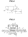
- each anvil 8 includes a parallel portion 14 in parallel with a proceeding direction of the slab 7, an inclined portion 15 at a rear end or an entry side facing the proceeding slab 7, and an inclined portion 15a on a front end or an exit side.
- the inclined portion 15a on the exit side is not necessarily needed.
- the slab 7 is transferred by pinch rolls 16 and a high speed transferring roller table 17.
- lower buckling preventing rollers 18 and upper buckling preventing rollers 19 may be provided in the housing 1 in order to prevent the buckling of the slab produced in reducing the width of the slab as shown in Fig. 5.
- the slab 7 is fed between the anvils 8 which have been set whose minimum distance therebetween is wider than a width of the slab 7 and stopped so as to permit a preceding end of the slab to be positioned at a location where an unsteady deformation caused by the preforming is minimum.
- the crankshaft 2 starts from a lower dead point (LDP in Fig. 6) to an upper dead point (UDP) to widen the distance between the slab 7 and one of the anvils 8. Therefore, during the movement of the crankshaft 2 from the lower dead point to the upper dead point, the screw-threaded rods 5 are rotated so as to move in its axial direction, so that the width reduction head 6 is moved relatively to the slider 4 so as to approach to the slab 7 (Figs. 7 and 8).
- the preforming of the trailing end of the slab can be effected in the same manner as that of the preceding end of the slab. Namely, before an irregular shape such as a "tongue" occurs at the trailing end of the slab, the slab is fed onto the exit side and the preforming of the trailing end is effected with an inclined portion 15a of the anvil at its front end or an exit side in the same manner as that of the preceding end. It is also possible to effect the preforming of the trailing end prior to the preforming of the preceding end.
- the slab is fed at a higher speed as shown in Fig. 10.
- the anvil 8 is operated with a constant stroke.
- the anvil 8 moves away from the slab 7. Accordingly, the slab 7 is fed between the pair of anvils 8 during the movement of the crankshaft 2 to the upper dead point, and the next reduction in width is effected during the movement of the crankshaft 2 from the upper dead point to the lower dead point.
- the slab is fed in increments of a predetermined distance which is referred to herein "pitch P" indicated in the following formulas, where an inclined angle of the inclined portion 15 of the anvil 8 is 0, a reduced distance of the slab 7 by one anvil 8 in one reduction is Y, a stroke of the anvil 8 is S t , and a distance of width of the slab to be reduced is Aw.
- P a predetermined distance which is referred to herein "pitch P" indicated in the following formulas, where an inclined angle of the inclined portion 15 of the anvil 8 is 0, a reduced distance of the slab 7 by one anvil 8 in one reduction is Y, a stroke of the anvil 8 is S t , and a distance of width of the slab to be reduced is Aw.
- a gap G in Fig. 11 serves to prevent any collision of the slab with the anvils.
- a rotating radius of crankshafts is 50 mm
- the reduced distance in width of slabs by one anvil is 175 mm
- the angle 0 of inclined portion of the anvil is 12 ° .
- Y uo is the movement of the anvil caused by the rotation of the crankshaft or the movement of the slider
- Y w is the width adjustment amount (in other words, the movement of the width reduction head)
- Y u is the substantial or actual movement of the anvil (Y uo +Yw).
- Y s indicates the variation in the distance between the side edge of the slab and the reduced position to be aimed by one anvil in a vertical line passing through the point A of the anvil.
- the gap G is the distance between the slab and the anvil.
- Fig. 12a illustrates a condition of preforming a preceding end of the slab 7.
- the anvil 8 is illustrated in an awaiting or posing position 8 0 in solid lines and in first and second stage preforming positions 8a and 8b in phantom lines.
- Y sa 85 mm
- Fig. 12b illustrates a condition of the steady reduction.
- the positions 8 0 and 8 c of the anvil correspond to the positions of the crankshaft at the upper dead point and lower dead point, respectively.
- the slab 7 is fed at a high speed from the position where the preceding reduction has been completed corresponding to the position 8c shown in Fig. 12a to the position shown in solid lines in a direction shown by an arrow F to effect a next reduction in width of the slab.
- Fig. 12c illustrates the preforming of a trailing end of the slab 7.
- the pair of anvils 8 are once opened to the positions 8 0 where the anvils 8 do not interfere with the slab 7 and the slab 7 is advanced by a distance L in the direction F.
- the slab 7 is stopped when the trailing end 7' arrives at a starting point B of the inclined portion of the anvil at its front end or the exit end, and the first and second stage preformings at the trailing end are effected.
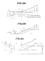
- Figs. 13a-13d illustrate the operation of one anvil corresponding to lapse of time during the preforming the preceding end, the steady reduction in width and the preforming the trailing end of the slab.
- a letter S is a point from which the anvil starts, and a letter P is a point from which the reduction in width of the slab starts by the anvil.
- a letter Z is a point at which the width adjustment has been completed.
- the anvil stands or waits at a point S a of 190 mm with a gap of 15 mm for the first stage preforming.
- the crankshaft starts to rotate from the lower dead point toward the upper dead point, so that this movement of the crankshaft causes the anvil moves along a curve Y uo .
- the width adjustment is effected along a curve Y w slightly behind the movement of the anvil along the curve Y uo and is stopped at a point Z a after the width adjustment of 100 mm. Therefore, the actual movement of the anvil is shown by a curve Y u .
- the first stage preforming is completed at a point S b .
- Fig. 13b illustrates the second stage preforming at the preceding end of the slab continuously following the above first stage preforming.
- an amount of the width adjustment is 90 mm because the total reduced distance by the anvil in the first and second stage preformings is 175 mm and the width adjustment of 85 mm in the first stage has been completed.
- Fig. 13c illustrates continuous steady width reduction.
- the slab starts to move slightly behind the crankshaft passing through the lower dead point S and stops short of the reduction starting point P.
- This stopped position of the slab is set so that the gap G is 15 mm and Y s is 85 mm at the location corresponding to the point A of the anvil (Fig. 12b) from which the inclined portion 15 of the anvil on the rear or entry side starts.
- Fig. 12b the anvil
- Fig. 13d illustrates the preforming the trailing end of the slab.
- the crankshaft continues its rotation to the upper dead point, during which the anvil moves along a curve Y uo .
- the width adjustment starts slightly behind the point S in the direction opening the pair of anvils to a value of 190 mm and then is once stopped as shown in a curve Y w1 . Thereafter, as shown in a curve Y w2 the width adjustment again starts in the direction closing the anvils to a value of 100 mm and thereafter the width adjustment is stopped at a point Z where the preforming of 85 mm at the trailing end is possible in the first stage preforming.
- the slab is moved and is stopped when the trailing end 7' of the slab arrives at a point B of the anvil.
- Y s increases progressively and passes through a point of 175 mm which has not been reduced, and the trailing end 7' intersects the line Y s .
- Y s ' indicates the distance in width to be reduced by one anvil in the vertical direction passing through the point B of the anvil.
- the actual movement of the anvil corresponds to a line Y u so that the gap of 15 mm can be maintained even when the anvil and the slab approach each other to the minimum possible distance.
- the reduction in width starts from the point P where the curves Y u and Y s ' intersects. Thereafter, the second stage preforming at the trailing end of the slab is effected in the same manner as shown in Fig. 13b.
- preforming of the trailing end is effected prior to preforming of the preceding end, it can be carried out by the use of the inclined portions 15a of the anvils on the exit side in the same manner as in the preceding end, although the case is not shown in the drawings.
- the reducing distance can be set according to the desired distance of reduction in width in continuous width reduction including the preforming of a slab, and the reduction in width of slabs can be continuously effected with the set reducing distance with high efficiency.
- the buckling is likely to occur when the reduction in width of the slab is effected as we mentioned in the preamble in the specification.
- the inventors of the invention have investigated the occurrence of the buckling to find that such a buckling throughout a slab from its preceding end to its trailing end can be prevented by holding the slab at more than two locations along a rolling direction or a longitudinal direction of the slab by means of, for example, rollers.
Claims (5)
Applications Claiming Priority (4)
| Application Number | Priority Date | Filing Date | Title |
|---|---|---|---|
| JP60261307A JPS62124044A (ja) | 1985-11-22 | 1985-11-22 | 熱間スラブの幅圧下プレス方法及び装置 |
| JP261307/85 | 1985-11-22 | ||
| JP26130785 | 1985-11-22 | ||
| EP86308240A EP0224333B2 (fr) | 1985-11-22 | 1986-10-23 | Presse pour réduire en largeur des brames chaudes |
Related Parent Applications (2)
| Application Number | Title | Priority Date | Filing Date |
|---|---|---|---|
| EP86308240A Division EP0224333B2 (fr) | 1985-11-22 | 1986-10-23 | Presse pour réduire en largeur des brames chaudes |
| EP86308240.0 Division | 1986-10-23 |
Publications (4)
| Publication Number | Publication Date |
|---|---|
| EP0353788A2 EP0353788A2 (fr) | 1990-02-07 |
| EP0353788A3 EP0353788A3 (en) | 1990-09-12 |
| EP0353788B1 true EP0353788B1 (fr) | 1993-12-29 |
| EP0353788B2 EP0353788B2 (fr) | 1999-08-18 |
Family
ID=17359971
Family Applications (2)
| Application Number | Title | Priority Date | Filing Date |
|---|---|---|---|
| EP89117570A Expired - Lifetime EP0353788B2 (fr) | 1985-11-22 | 1986-10-23 | Procédé et dispositif pour réduire en largeur des brames chaudes |
| EP86308240A Expired - Lifetime EP0224333B2 (fr) | 1985-11-22 | 1986-10-23 | Presse pour réduire en largeur des brames chaudes |
Family Applications After (1)
| Application Number | Title | Priority Date | Filing Date |
|---|---|---|---|
| EP86308240A Expired - Lifetime EP0224333B2 (fr) | 1985-11-22 | 1986-10-23 | Presse pour réduire en largeur des brames chaudes |
Country Status (8)
| Country | Link |
|---|---|
| US (2) | US4760728A (fr) |
| EP (2) | EP0353788B2 (fr) |
| JP (1) | JPS62124044A (fr) |
| KR (1) | KR900007957B1 (fr) |
| AU (1) | AU583430B2 (fr) |
| BR (1) | BR8605216A (fr) |
| CA (1) | CA1296551C (fr) |
| DE (2) | DE3679387D1 (fr) |
Families Citing this family (16)
| Publication number | Priority date | Publication date | Assignee | Title |
|---|---|---|---|---|
| JPH0679721B2 (ja) * | 1986-12-01 | 1994-10-12 | 川崎製鉄株式会社 | スラブの幅圧下方法 |
| JPH0824940B2 (ja) * | 1988-03-18 | 1996-03-13 | 石川島播磨重工業株式会社 | 幅圧下プレスの座屈防止装置 |
| US4930207A (en) * | 1988-06-07 | 1990-06-05 | Kawasaki Steel Corp. | Method and apparatus for continuous compression forging of continuously cast steel |
| CA1325615C (fr) * | 1988-08-26 | 1993-12-28 | Geoffrey Wilson | Procede et dispositif de transformation de brames |
| DE3900668C2 (de) * | 1989-01-09 | 2001-01-11 | Mannesmann Ag | Presse zum seitlichen Stauchen von Werkstücken, insbesondere Brammenstauchpresse |
| JP2707683B2 (ja) * | 1989-03-01 | 1998-02-04 | 石川島播磨重工業株式会社 | 幅圧下プレスの座屈防止押えロール装置 |
| DE3917398A1 (de) * | 1989-05-29 | 1990-12-06 | Schloemann Siemag Ag | Fliegende stauchpresse |
| US5046344A (en) * | 1990-01-19 | 1991-09-10 | United Engineering, Inc. | Apparatus for sizing a workpiece |
| DE4035000A1 (de) * | 1990-11-03 | 1992-05-07 | Schloemann Siemag Ag | Vorrichtung zum verspannen und ausbalancieren von presswerkzeugtraeger und kurbelgehaeuse einer stauchpresse |
| DE4035001A1 (de) * | 1990-11-03 | 1992-05-07 | Schloemann Siemag Ag | Stauchpresse zur reduktion der breite von brammen in warmbreitband-vorstrassen |
| IT1288870B1 (it) * | 1996-03-25 | 1998-09-25 | Danieli Off Mecc | Dispositivo di compattazione laterale per bramme |
| JP3381584B2 (ja) * | 1997-10-31 | 2003-03-04 | 株式会社日立製作所 | スラブサイジングプレス |
| TR200502554T1 (tr) * | 1999-03-10 | 2007-01-22 | Ishikawajima-Harimaheavy Industries Co., Ltd | Sıcak haddeli çelik plaka üretimi cihazı ve yöntemi. |
| JP3511482B2 (ja) * | 1999-05-10 | 2004-03-29 | 株式会社日立製作所 | スラブサイジングプレス |
| US6601429B2 (en) * | 2000-04-12 | 2003-08-05 | Sms Demag Aktiengesellschaft | Upsetting tool for forming continuous cast slab in slab upsetting presses |
| JP6544339B2 (ja) * | 2016-11-08 | 2019-07-17 | Jfeスチール株式会社 | 熱間スラブの幅圧下方法 |
Family Cites Families (24)
| Publication number | Priority date | Publication date | Assignee | Title |
|---|---|---|---|---|
| US391825A (en) * | 1888-10-30 | taylor | ||
| US2114302A (en) * | 1936-11-10 | 1938-04-19 | Babcock & Wilcox Tube Company | Method of making round billets |
| DE1050154B (de) * | 1956-03-19 | 1959-02-05 | Champigny Seine Rene Etienne Bujon (Frankreich) | Hämmermaschine zum Herstellen von Profilstäben |
| GB964008A (en) * | 1960-02-11 | 1964-07-15 | Hydraulik Gmbh | Method and apparatus for the production of blanks from cast ingots |
| GB1039518A (en) * | 1962-12-04 | 1966-08-17 | Davy & United Eng Co Ltd | Improvements in or relating to forging proesses |
| US3495427A (en) * | 1965-04-05 | 1970-02-17 | Cavitron Corp | Apparatus for altering the cross-sectional shape of a plastically deformable workpiece using high frequency vibrations |
| AT311768B (de) * | 1972-06-09 | 1973-12-10 | Gfm Fertigungstechnik | Schnellhubschmiedepresse |
| SU508319A1 (ru) * | 1973-04-09 | 1976-03-30 | Рязанский завод тяжелого кузнечно-прессового оборудования | Радиально-ковочна машина |
| DE2411340A1 (de) * | 1974-03-09 | 1975-09-18 | Hasenclever Gmbh Maschf | Schmiedepresse |
| US3921429A (en) * | 1974-04-11 | 1975-11-25 | Tadeusz Sendzimir | Process and apparatus for modifying the cross section of a slab |
| JPS5516719A (en) * | 1978-07-19 | 1980-02-05 | Ishikawajima Harima Heavy Ind Co Ltd | Lateral draft rolling mill |
| JPS5666305A (en) * | 1979-10-31 | 1981-06-04 | Hitachi Ltd | Method and apparauts for edging slab |
| JPS57168707A (en) * | 1981-04-08 | 1982-10-18 | Ishikawajima Harima Heavy Ind Co Ltd | Edger having buckling preventing device |
| JPS5853301A (ja) * | 1981-09-24 | 1983-03-29 | Hitachi Ltd | 板材の幅圧延におけるプレス予成形方法 |
| JPS58199601A (ja) * | 1982-05-17 | 1983-11-21 | Sumitomo Metal Ind Ltd | エツジヤ |
| DE3376530D1 (en) * | 1982-12-01 | 1988-06-16 | Hitachi Ltd | Press apparatus for reducing slab width |
| JPH0824922B2 (ja) * | 1982-12-01 | 1996-03-13 | 株式会社日立製作所 | プレス式スラブ幅減少方法、及びその装置 |
| JPS59165702U (ja) * | 1983-04-25 | 1984-11-07 | 石川島播磨重工業株式会社 | 竪型圧延機 |
| JPS60121001A (ja) * | 1983-12-02 | 1985-06-28 | Hitachi Ltd | 幅圧延装置 |
| JPS60133901A (ja) * | 1983-12-22 | 1985-07-17 | Ishikawajima Harima Heavy Ind Co Ltd | 対向型プレス |
| EP0157575B2 (fr) * | 1984-03-29 | 1996-04-10 | Kawasaki Steel Corporation | Procédé de réduction en largeur de plaques par pressage et presse à cet effet |
| JPH0683841B2 (ja) * | 1984-03-29 | 1994-10-26 | 川崎製鉄株式会社 | 熱間スラブの幅圧下方法 |
| JPS61212401A (ja) * | 1985-03-18 | 1986-09-20 | Kawasaki Steel Corp | テ−パスラブの幅圧下方法 |
| JPH0671607B2 (ja) * | 1985-10-28 | 1994-09-14 | 石川島播磨重工業株式会社 | 幅プレスの座屈防止方法及び装置 |
-
1985
- 1985-11-22 JP JP60261307A patent/JPS62124044A/ja active Granted
-
1986
- 1986-10-20 AU AU64220/86A patent/AU583430B2/en not_active Expired
- 1986-10-21 US US06/921,549 patent/US4760728A/en not_active Expired - Lifetime
- 1986-10-23 EP EP89117570A patent/EP0353788B2/fr not_active Expired - Lifetime
- 1986-10-23 DE DE8686308240T patent/DE3679387D1/de not_active Expired - Lifetime
- 1986-10-23 CA CA000521205A patent/CA1296551C/fr not_active Expired - Lifetime
- 1986-10-23 EP EP86308240A patent/EP0224333B2/fr not_active Expired - Lifetime
- 1986-10-23 DE DE3689484T patent/DE3689484T3/de not_active Expired - Lifetime
- 1986-10-24 KR KR1019860008935A patent/KR900007957B1/ko not_active IP Right Cessation
- 1986-10-24 BR BR8605216A patent/BR8605216A/pt not_active IP Right Cessation
-
1988
- 1988-05-06 US US07/190,997 patent/US4852383A/en not_active Expired - Lifetime
Also Published As
| Publication number | Publication date |
|---|---|
| EP0224333A3 (en) | 1987-10-28 |
| BR8605216A (pt) | 1987-07-28 |
| US4760728A (en) | 1988-08-02 |
| JPH0462803B2 (fr) | 1992-10-07 |
| EP0224333B2 (fr) | 1997-01-29 |
| DE3689484T2 (de) | 1994-04-21 |
| KR870004740A (ko) | 1987-06-01 |
| DE3689484T3 (de) | 2000-04-27 |
| DE3689484D1 (de) | 1994-02-10 |
| AU583430B2 (en) | 1989-04-27 |
| EP0353788A3 (en) | 1990-09-12 |
| DE3679387D1 (de) | 1991-06-27 |
| JPS62124044A (ja) | 1987-06-05 |
| EP0353788B2 (fr) | 1999-08-18 |
| KR900007957B1 (ko) | 1990-10-23 |
| US4852383A (en) | 1989-08-01 |
| AU6422086A (en) | 1987-05-28 |
| EP0353788A2 (fr) | 1990-02-07 |
| EP0224333A2 (fr) | 1987-06-03 |
| CA1296551C (fr) | 1992-03-03 |
| EP0224333B1 (fr) | 1991-05-22 |
Similar Documents
| Publication | Publication Date | Title |
|---|---|---|
| EP0353788B1 (fr) | Procédé et dispositif pour réduire en largeur des brames chaudes | |
| US3333452A (en) | Reduction of thick flat articles | |
| EP1679135B1 (fr) | Dispositif de formage sous pression d'une plaque et procédés | |
| EP1452245B1 (fr) | Dispositif de fabrication de tôle d'acier laminée à chaud | |
| GB1577021A (en) | Methods of cutting flat material and apparatus therefore | |
| US3921429A (en) | Process and apparatus for modifying the cross section of a slab | |
| EP0400385B1 (fr) | Presse à refouler volante | |
| US4074557A (en) | Metal extrusion process with high reduction | |
| US3392566A (en) | Metal rolling | |
| DE60020673T2 (de) | Verfahren zum herstellen von warmgewalztem stahlblech | |
| EP0470436A2 (fr) | Rouleau de presse-tôle pour la suppression des brames dans une presse à refouler | |
| JP3203032B2 (ja) | 据込みプレスを運転するための方法 | |
| EP0132136B1 (fr) | Procédé et dispositif pour laminer les côtés d'acier en barres plates | |
| US4363234A (en) | Method and apparatus for forging sections | |
| JPH0250807B2 (fr) | ||
| WO2003027337A1 (fr) | Traitement par canaux angulaires ameliore | |
| JPH08224605A (ja) | 熱間スラブの幅圧下プレス装置及びこの装置を用いた幅圧下プレス方法 | |
| EP0028507B1 (fr) | Procédé de façonnage de métal | |
| EP0431058B1 (fr) | Procédé pour façonner les brames | |
| RU2356668C1 (ru) | Способ изготовления изделий переменного сечения из легких сплавов | |
| JP3120004B2 (ja) | 鍛造による金属形材の造形方法およびその装置 | |
| RU32714U1 (ru) | Линия для изготовления профиля сетчатого | |
| JP3120005B2 (ja) | 鍛造による金属形材の造形方法 | |
| JPH06254601A (ja) | 不等辺山形鋼の圧延方法 | |
| RU2240195C1 (ru) | Линия для изготовления профиля сетчатого |
Legal Events
| Date | Code | Title | Description |
|---|---|---|---|
| PUAI | Public reference made under article 153(3) epc to a published international application that has entered the european phase |
Free format text: ORIGINAL CODE: 0009012 |
|
| 17P | Request for examination filed |
Effective date: 19891006 |
|
| AC | Divisional application: reference to earlier application |
Ref document number: 224333 Country of ref document: EP |
|
| AK | Designated contracting states |
Kind code of ref document: A2 Designated state(s): BE DE FR GB IT NL |
|
| PUAL | Search report despatched |
Free format text: ORIGINAL CODE: 0009013 |
|
| AK | Designated contracting states |
Kind code of ref document: A3 Designated state(s): BE DE FR GB IT NL |
|
| 17Q | First examination report despatched |
Effective date: 19911204 |
|
| GRAA | (expected) grant |
Free format text: ORIGINAL CODE: 0009210 |
|
| ITF | It: translation for a ep patent filed |
Owner name: ING. GIOVANNI ARENA |
|
| AC | Divisional application: reference to earlier application |
Ref document number: 224333 Country of ref document: EP |
|
| AK | Designated contracting states |
Kind code of ref document: B1 Designated state(s): BE DE FR GB IT NL |
|
| REF | Corresponds to: |
Ref document number: 3689484 Country of ref document: DE Date of ref document: 19940210 |
|
| ET | Fr: translation filed | ||
| PLBI | Opposition filed |
Free format text: ORIGINAL CODE: 0009260 |
|
| 26 | Opposition filed |
Opponent name: SMS SCHLOEMANN-SIEMAG AKTIENGESELLSCHAFT Effective date: 19940929 |
|
| NLR1 | Nl: opposition has been filed with the epo |
Opponent name: SMS SCHLOEMANN-SIEMAG AKTIENGESELLSCHAFT |
|
| RDAH | Patent revoked |
Free format text: ORIGINAL CODE: EPIDOS REVO |
|
| APAC | Appeal dossier modified |
Free format text: ORIGINAL CODE: EPIDOS NOAPO |
|
| APAE | Appeal reference modified |
Free format text: ORIGINAL CODE: EPIDOS REFNO |
|
| APAC | Appeal dossier modified |
Free format text: ORIGINAL CODE: EPIDOS NOAPO |
|
| PLAW | Interlocutory decision in opposition |
Free format text: ORIGINAL CODE: EPIDOS IDOP |
|
| PUAH | Patent maintained in amended form |
Free format text: ORIGINAL CODE: 0009272 |
|
| STAA | Information on the status of an ep patent application or granted ep patent |
Free format text: STATUS: PATENT MAINTAINED AS AMENDED |
|
| 27A | Patent maintained in amended form |
Effective date: 19990818 |
|
| AK | Designated contracting states |
Kind code of ref document: B2 Designated state(s): BE DE FR GB IT NL |
|
| ITF | It: translation for a ep patent filed |
Owner name: ING. GIOVANNI ARENA |
|
| ET3 | Fr: translation filed ** decision concerning opposition | ||
| NLR3 | Nl: receipt of modified translations in the netherlands language after an opposition procedure | ||
| REG | Reference to a national code |
Ref country code: GB Ref legal event code: IF02 |
|
| PGFP | Annual fee paid to national office [announced via postgrant information from national office to epo] |
Ref country code: IT Payment date: 20050708 Year of fee payment: 20 |
|
| APAH | Appeal reference modified |
Free format text: ORIGINAL CODE: EPIDOSCREFNO |
|
| PGFP | Annual fee paid to national office [announced via postgrant information from national office to epo] |
Ref country code: FR Payment date: 20051010 Year of fee payment: 20 |
|
| PGFP | Annual fee paid to national office [announced via postgrant information from national office to epo] |
Ref country code: NL Payment date: 20051016 Year of fee payment: 20 |
|
| PGFP | Annual fee paid to national office [announced via postgrant information from national office to epo] |
Ref country code: GB Payment date: 20051019 Year of fee payment: 20 |
|
| PGFP | Annual fee paid to national office [announced via postgrant information from national office to epo] |
Ref country code: DE Payment date: 20051020 Year of fee payment: 20 |
|
| PGFP | Annual fee paid to national office [announced via postgrant information from national office to epo] |
Ref country code: BE Payment date: 20051215 Year of fee payment: 20 |
|
| PG25 | Lapsed in a contracting state [announced via postgrant information from national office to epo] |
Ref country code: GB Free format text: LAPSE BECAUSE OF EXPIRATION OF PROTECTION Effective date: 20061022 |
|
| PG25 | Lapsed in a contracting state [announced via postgrant information from national office to epo] |
Ref country code: NL Free format text: LAPSE BECAUSE OF EXPIRATION OF PROTECTION Effective date: 20061023 |
|
| REG | Reference to a national code |
Ref country code: GB Ref legal event code: PE20 |
|
| NLV7 | Nl: ceased due to reaching the maximum lifetime of a patent |
Effective date: 20061023 |
|
| BE20 | Be: patent expired |
Owner name: *HITACHI LTD Effective date: 20061023 Owner name: *KAWASAKI STEEL CORP. Effective date: 20061023 |