EP0349725A1 - Schrank mit mindestens einem innenliegenden Regalteil - Google Patents
Schrank mit mindestens einem innenliegenden Regalteil Download PDFInfo
- Publication number
- EP0349725A1 EP0349725A1 EP89107855A EP89107855A EP0349725A1 EP 0349725 A1 EP0349725 A1 EP 0349725A1 EP 89107855 A EP89107855 A EP 89107855A EP 89107855 A EP89107855 A EP 89107855A EP 0349725 A1 EP0349725 A1 EP 0349725A1
- Authority
- EP
- European Patent Office
- Prior art keywords
- shelf
- cabinet
- body part
- rear wall
- cabinet according
- Prior art date
- Legal status (The legal status is an assumption and is not a legal conclusion. Google has not performed a legal analysis and makes no representation as to the accuracy of the status listed.)
- Granted
Links
Images
Classifications
-
- A—HUMAN NECESSITIES
- A47—FURNITURE; DOMESTIC ARTICLES OR APPLIANCES; COFFEE MILLS; SPICE MILLS; SUCTION CLEANERS IN GENERAL
- A47B—TABLES; DESKS; OFFICE FURNITURE; CABINETS; DRAWERS; GENERAL DETAILS OF FURNITURE
- A47B67/00—Chests; Dressing-tables; Medicine cabinets or the like; Cabinets characterised by the arrangement of drawers
- A47B67/005—Mirror cabinets; Dressing-tables
-
- A—HUMAN NECESSITIES
- A47—FURNITURE; DOMESTIC ARTICLES OR APPLIANCES; COFFEE MILLS; SPICE MILLS; SUCTION CLEANERS IN GENERAL
- A47G—HOUSEHOLD OR TABLE EQUIPMENT
- A47G1/00—Mirrors; Picture frames or the like, e.g. provided with heating, lighting or ventilating means
- A47G1/02—Mirrors used as equipment
- A47G1/04—Multi-part mirrors
Definitions
- the present invention relates to a cabinet with at least one internal shelf part according to the preamble of claim 1.
- the body part occupies a fixed position, while the shelf part can be pulled out of the body part.
- a front mirror is arranged between two opposing shelf parts enclosed by a respective body part, which can be, for example, the front door of a cabinet provided with compartments.
- the shelf parts of this known mirror cabinet can also be pulled out of the body, with their direction of pull extending transversely to the front mirror.
- the risk of the objects stored in the shelf part tipping over is also very great, and containers containing liquid, such as perfume bottles or the like, are often kept, which can easily fall off the shelf and break.
- the present invention is therefore based on the object of designing a cabinet of the generic type in such a way that its usability is improved and the manufacturing costs are reduced.
- the dimensioning of the guide elements can be considerably reduced compared to the known cabinet, since the weight of the body part is significantly less than the total weight of the shelf part to be moved so far and the content.
- Another significant advantage of the invention is the fact that the shelf content is not affected by the always constant position of the shelf part by opening the cabinet and the resulting vibrations, such as have occurred so far, so that the risk of the opening of the cupboard parts of the shelf contents no longer fall out.
- the invention can be used particularly advantageously in a mirror cabinet in which the mutually facing body sides have mirrors which are arranged, for example, at an obtuse angle to the front mirrors connecting the two shelf parts to one another.
- a user of the mirror cabinet is thus able to look at the rear in different positions depending on the position of the body part by moving the body part relative to the shelf part.
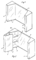
- a so-called mirror cabinet is shown, as it is preferably used in bathrooms.
- This mirror cabinet consists of two opposite cabinets 1, which are connected by a front mirror 4.
- FIGS. 4 and 5 clearly show, the front mirror 4 is fastened to a rear wall 7.
- Each cabinet 1 has a shelf part 3, which is fixed to the rear wall 7, and a body part 2, the body part 2 ent opposite the fixed shelf part 3 speaking the arrow directions is displaceable.
- the body part 2 consists of a body side 10 pointing in the direction of the other cabinet 1, corresponding to the illustrations in FIGS. 4 and 5, a body rear wall 9 and a front bar 11 connecting the body rear wall 9 and the body side 10.
- the body side 10, on which a side mirror 5 is fixed, runs at an obtuse angle to the front mirror 4, while the body rear wall 9 is arranged at right angles thereto.
- the shelf part 3 is provided on the top with a cover plate 12, so that when the cabinet 1 is not in use it is completely closed.
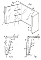
- FIG. 4 One possibility of the sliding direction is shown in FIG. 4.
- the body rear wall 9 is guided parallel to the shelf wall 8, which is arranged at right angles to the rear wall 7.
- This embodiment offers the advantage that 9 further shelves, cupboards directly after the body rear wall or the like can be arranged, since there is no further, increasing space on the side.
- this embodiment has the advantage that there is better access to the shelf area.
- a change in the position of the two opposite side mirrors 5 is conceivable not only by moving the body part 1, but also, for example, by pivoting it in a suitable manner to the body side 10.
- the body part 2 consists of the body side 10 facing the front mirror 4 and provided with the side mirror 5 and the front strip 11. In this case, the rear wall of the body is missing, and the body part 2 is expediently guided in accordance with the embodiment according to FIG. 5.
Landscapes
- Mirrors, Picture Frames, Photograph Stands, And Related Fastening Devices (AREA)
- Devices For Indicating Variable Information By Combining Individual Elements (AREA)
- Combinations Of Kitchen Furniture (AREA)
- Casings For Electric Apparatus (AREA)
Abstract
Description
- Die vorliegende Erfindung betrifft einen Schrank mit mindestens einem innenliegenden Regalteil gemäß dem Oberbegriff des Anspruchs 1.
- Derartige Schränke sind aus vielen Verwendungsbereichen bekannt.
- Dabei nimmt das korpusteil eine ortsfeste Lage ein, während das Regalteil aus dem Korpusteil herausziehbar ist.
- Zwar wird bei solcherart ausgebildeten Schränken der Zugriff zum Regalinhalt gegenüber den Schränken verbessert, bei denen das Regalteil und das Korpusteil gemeinsam eine Einheit bilden, jedoch treten dabei nicht nur statische Probleme auf, da das bewegbare Regalteil entsprechend der durch den Regalinhalt auftretenden Belastung dimensioniert sein muß.
Darüber hinaus müssen auch entsprechende Vorkehrungen getroffen werden, um den Regalinhalt bei der Hin- und Herbewegung des Regalteiles zu arretieren. - Gattungsgemäße Schränken finden vielfach auch im Badbereich Verwendung, wo sie als sogenannte Spiegelschränke zum Einsatz konnen.
- Dabei ist zwischen zwei sich gegenüberliegenden, durch ein jeweiliges Korpusteil umschlossenen Regalteilen ein Frontspiegel angeordnet der beispielsweise die Fronttür eines mit Fächern versehenen Schrankes sein kann.
- Die Regalteile dieses bekannten Spiegelschrankes sind dabei ebenfalls aus dem Korpus herausziehbar, wobei ihre Ziehrichtung quer zum Frontspiegel verläuft.
Auch hier ergeben sich die oben erwähnten Nachteile hinsichtlich einer eingeschränkten Belastbarkeit bzw. einer erforderlichen großzügigen Dimensionierung des Regalteiles bzw. deren Führungsteil, die entsprechend der maximalen Belastung durch den Regalinhalt ausgelegt sein muß. Überdies ist auch hier die Gefahr des Umkippens der im Regalteil aufbewahrten Gegenstände sehr groß wobei vielfach Flüssigkeit beinhaltende Behälter, wie Parfümfläschchen oder dergleichen aufbewahrt werden, die leicht aus dem Regal fallen und zerbrechen können. - Der vorliegenden Erfindung liegt daher die Aufgabe zugrunde, einen Schrank der gattungsgemäßen Art so zu gestalten, daß seine Verwendungsfähigkeit verbessert und die Herstellkosten gesenkt werden.
- Diese Aufgabe wird erfindungsgemäß durch die im kennzeichnenden Teil des Anspruchs 1 genannten Merkmale gelöst.
- Da nunmehr das Regalteil zusammen mit dem Inhalt ortsfest bleibt und der Zugriff auf das Innere des Regalteiles durch Verschieben des Korpusteiles möglich wird, kann die Dimensionierung der Führungselemente, gegenüber dem bekannten Schrank erheblich verringert werden, da das Gewicht des Korpusteiles wesentlich geringer ist als das Gesamtgewicht des bislang zu bewegenden Regalteiles und des Inhaltes.
- Naturgemäß ergibt sich daraus eine Senkung der Herstellkosten, wobei durchaus auch eine Erhöhung der Lebensdauer eines derartigen Schrankes durch eine geringere Beanspruchung zu berücksichtigen ist.
- Natürlich wäre im Umkehrschluß auch eine Erhöhung der Belastung des Regalteiles denkbar, da nun die Auslegung der das Korpusteil tragenden Führungselemente ausschließlich vom Gewicht des Korpusteiles abhängig ist.
- Ein weiterer, erheblicher Vorteil der Erfindung ist darin zu sehen, daß der Regalinhalt durch die stets gleichbleibende Lage des Regalteiles durch das Öffnen des Schrankes und die dabei entstehenden Erschütterungen, wie sie bislang erfolgten, nicht beeinträchtigt wird, so daß auch die Gefahr, daß durch das Öffnen des Schrankes Teile des Regalinhalts herausfallen nicht mehr gegeben ist.
- Besonders vorteilhaft läßt sich die Erfindung bei einem Spiegelschrank einsetzen, bei dem die einander zugewandten Korpusseiten Spiegel aufweisen, die beispielsweise stumpfwinklig zu den die beiden Regalteile miteinander verbindenden Frontspiegel angeordnet sind.
- Ein Benutzer des Spiegelschrankes ist somit in der Lage, sich durch Verschieben des Korpusteiles gegenüber dem Regalteil je nach Stellung des Korpusteiles in unterschiedlichen Positionen rückseitig zu betrachten.
- Weitere vorteilhafte Ausgestaltungen sind in den Unteransprüchen gekennzeichnet.
- Ausführungsbeispiele der Erfindung werden nachfolgend anhand beigefügter Zeichnungen beschrieben.
- Es zeigen:
- Fig. 1 - 3 verschiedene Ausführungsbeispiele eines erfindungsgemäßen Schrankes in perspektivischer Darstellung,
- Fig. 4 + 5 Teilquerschnitte durch unterschiedlich gestaltete, erfindungsgemäße Schränke.
- In den Figuren 1 bis 3 ist ein sogenannter Spiegelschrank dargestellt, wie er bevorzugt in Bädern Verwendung findet. Dieser Spiegelschrank besteht aus zwei sich gegenüberliegenden Schränken 1, die durch einen Frontspiegel 4 miteinander verbunden sind.
Wie die Figuren 4 und 5 deutlich zeigen, ist der Frontspiegel 4 an einer Rückwand 7 befestigt. - Jeder Schrank 1 weist ein Regalteil 3, das an der Rückwand 7 festgelegt ist, und ein Korpusteil 2 auf, wobei das Korpusteil 2 gegenüber dem feststehenden Regalteil 3 ent sprechend den Pfeilrichtungen verschiebbar ist.
- Bei dem in der Figur 2 dargestellten Ausführungsbeispiel besteht das Korpusteil 2 aus einer in Richtung des anderen Schrankes 1 weisenden Korpusseite 10, entsprechend den Darstellungen der Figuren 4 und 5, einer Korpusrückwand 9 und einer die Korpusrückwand 9 und die Korpusseite 10 verbindenden Frontleiste 11.
- Die Korpusseite 10, an der ein Seitenspiegel 5 festgelegt ist, verläuft stumpfwinklig zum Frontspiegel 4, während die Korpusrückwand 9 rechtwinklig dazu angeordnet ist.
- Entsprechend ergibt sich eine etwa dreieck- bzw. trapezförmige Grundfläche, der in dem Regalteil 3 einliegende Regalböden 6 angepaßt sind.
- Das Regalteil 3 ist oberseitig mit einer Deckplatte 12 versehen, so daß in Nichtgebrauchsstellung des Schrankes 1 dieser vollständig geschlossen ist.
- Neben der in den Figuren dargestellten Ausführungsform der Deckplatte 12 besteht auch die Möglichkeit, beide Schränke 1 beispielsweise durch eine geschlossene Leuchtenleiste abzudecken.
- Eine Möglichkeit der Schieberichtung ist in der Figur 4 dargestellt.
Dabei wird die Korpusrückwand 9 parallel zur Regalwand 8, die ja rechtwinklig zur Rückwand 7 angeordnet ist, geführt. Diese Ausführungsform bietet den Vorteil, daß direkt im Anschluß an die Korpusrückwand 9 weitere Regale, Schränke oder dergleichen angeordnet werden können, da seitlich kein weiterer, zunehmender Platzbedarf besteht. - Dies ist allerdings bei dem in der Figur 5 dargestellten Ausführungsbeispiel der Fall, bei dem sich der Abstand der Korpusrückwand 9 zur Regalwand mit einem Verschieben des Korpusteiles 2 verändert, da hier die Führung entlang der Verlaufslinie der Korpusseite 10 erfolgt.
- Diese Ausführungsform hat allerdings den Vorteil, daß eine bessere Zugriffsmöglichkeit in den Regalbereich gegeben ist.
- Eine Veränderung der Lage der beiden sich gegenüberliegenden Seitenspiegel 5 ist aber nicht nur durch das Verschieben des Korpusteiles 1 denkbar, sondern beispielsweise auch dadurch, daß er in geeigneter Weise schwenkbar mit der Korpusseite 10 verbunden ist.
- Bei dem in der Figur 3 dargestellten Ausführungsbeispiel besteht das Korpusteil 2 aus der den Frontspiegel 4 zugewandten, mit dem Seitenspiegel 5 versehenen Korpusseite 10 und der Frontleiste 11.
In diesem Fall fehlt also die Korpusrückwand, wobei die Führung des Korpusteiles 2 zweckmäßiger Weise entsprechend der Ausführung nach der Figur 5 erfolgt. -
- 1 Schrank
- 2 Korpusteil
- 3 Regalteil
- 4 Frontspiegel
- 5 Seitenspiegel
- 6 Regalboden
- 7 Rückwand
- 8 Regalwand
- 9 Korpusrückwand
- 10 Korpusseite
- 11 Frontleiste
- 12 Deckplatte
Claims (8)
daß das Korpusteil (2) zumindest teilweise gegenüber dem Regalteil (3) verschiebbar ist.
Priority Applications (1)
| Application Number | Priority Date | Filing Date | Title |
|---|---|---|---|
| AT89107855T ATE79520T1 (de) | 1988-07-08 | 1989-04-29 | Schrank mit mindestens einem innenliegenden regalteil. |
Applications Claiming Priority (2)
| Application Number | Priority Date | Filing Date | Title |
|---|---|---|---|
| DE3823150 | 1988-07-08 | ||
| DE3823150A DE3823150A1 (de) | 1988-07-08 | 1988-07-08 | Schrank mit mindestens einem innenliegenden regalteil |
Publications (2)
| Publication Number | Publication Date |
|---|---|
| EP0349725A1 true EP0349725A1 (de) | 1990-01-10 |
| EP0349725B1 EP0349725B1 (de) | 1992-08-19 |
Family
ID=6358242
Family Applications (1)
| Application Number | Title | Priority Date | Filing Date |
|---|---|---|---|
| EP89107855A Expired - Lifetime EP0349725B1 (de) | 1988-07-08 | 1989-04-29 | Schrank mit mindestens einem innenliegenden Regalteil |
Country Status (4)
| Country | Link |
|---|---|
| EP (1) | EP0349725B1 (de) |
| AT (1) | ATE79520T1 (de) |
| DE (2) | DE3823150A1 (de) |
| ES (1) | ES2034470T3 (de) |
Cited By (2)
| Publication number | Priority date | Publication date | Assignee | Title |
|---|---|---|---|---|
| EP0505625A1 (de) * | 1991-03-18 | 1992-09-30 | Burg-Badmöbel Gmbh | Badmöbel |
| GB2363712A (en) * | 2000-06-23 | 2002-01-09 | Goody Prod Inc | Multiple use mirror assembly |
Citations (11)
| Publication number | Priority date | Publication date | Assignee | Title |
|---|---|---|---|---|
| US1868104A (en) * | 1929-04-08 | 1932-07-19 | Joseph A Hoegger | Mirror dresser |
| GB408324A (en) * | 1932-10-07 | 1934-04-09 | Yager London Ltd H | Improvements in and relating to dressing tables and the like |
| US1966800A (en) * | 1931-09-18 | 1934-07-17 | Katzman Harris | Toilet cabinet |
| FR828252A (fr) * | 1936-10-26 | 1938-05-13 | Armoire avec jeu de miroirs plans | |
| FR987579A (fr) * | 1949-03-30 | 1951-08-16 | Kohl & Cie | Glace à trois faces escamotable |
| DE851675C (de) * | 1951-01-13 | 1952-10-06 | Lutz Dr Schneider | Schrankmoebel mit eingebautem Mehrfachtoilettenspiegel |
| DE880641C (de) * | 1951-01-16 | 1953-06-22 | Lutz Dr Schneider | Mehrteiliges Toilettenwandschraenkchen mit Spiegeln |
| FR1264643A (fr) * | 1960-05-13 | 1961-06-23 | Miroiterie Georges Soc Nouv | Article mobilier mural de rangement à usages multiples |
| FR2017103A1 (de) * | 1968-08-30 | 1970-05-15 | Weil Stefan | |
| US3936669A (en) * | 1974-07-11 | 1976-02-03 | Marton C. Gaston | Beauty swag lamp |
| DE8808768U1 (de) * | 1988-07-08 | 1988-09-01 | Burg-Badmöbel GmbH, 5948 Schmallenberg | Frisierspiegel |
Family Cites Families (2)
| Publication number | Priority date | Publication date | Assignee | Title |
|---|---|---|---|---|
| DE1892748U (de) * | 1964-03-04 | 1964-05-14 | Evangelos Wonisakos | Schrank. |
| DE7603039U1 (de) * | 1976-02-04 | 1977-03-10 | Heeg, Otto, 6450 Hanau | Spiegelschrank |
-
1988
- 1988-07-08 DE DE3823150A patent/DE3823150A1/de active Granted
-
1989
- 1989-04-29 AT AT89107855T patent/ATE79520T1/de not_active IP Right Cessation
- 1989-04-29 DE DE8989107855T patent/DE58902071D1/de not_active Expired - Fee Related
- 1989-04-29 ES ES198989107855T patent/ES2034470T3/es not_active Expired - Lifetime
- 1989-04-29 EP EP89107855A patent/EP0349725B1/de not_active Expired - Lifetime
Patent Citations (11)
| Publication number | Priority date | Publication date | Assignee | Title |
|---|---|---|---|---|
| US1868104A (en) * | 1929-04-08 | 1932-07-19 | Joseph A Hoegger | Mirror dresser |
| US1966800A (en) * | 1931-09-18 | 1934-07-17 | Katzman Harris | Toilet cabinet |
| GB408324A (en) * | 1932-10-07 | 1934-04-09 | Yager London Ltd H | Improvements in and relating to dressing tables and the like |
| FR828252A (fr) * | 1936-10-26 | 1938-05-13 | Armoire avec jeu de miroirs plans | |
| FR987579A (fr) * | 1949-03-30 | 1951-08-16 | Kohl & Cie | Glace à trois faces escamotable |
| DE851675C (de) * | 1951-01-13 | 1952-10-06 | Lutz Dr Schneider | Schrankmoebel mit eingebautem Mehrfachtoilettenspiegel |
| DE880641C (de) * | 1951-01-16 | 1953-06-22 | Lutz Dr Schneider | Mehrteiliges Toilettenwandschraenkchen mit Spiegeln |
| FR1264643A (fr) * | 1960-05-13 | 1961-06-23 | Miroiterie Georges Soc Nouv | Article mobilier mural de rangement à usages multiples |
| FR2017103A1 (de) * | 1968-08-30 | 1970-05-15 | Weil Stefan | |
| US3936669A (en) * | 1974-07-11 | 1976-02-03 | Marton C. Gaston | Beauty swag lamp |
| DE8808768U1 (de) * | 1988-07-08 | 1988-09-01 | Burg-Badmöbel GmbH, 5948 Schmallenberg | Frisierspiegel |
Cited By (2)
| Publication number | Priority date | Publication date | Assignee | Title |
|---|---|---|---|---|
| EP0505625A1 (de) * | 1991-03-18 | 1992-09-30 | Burg-Badmöbel Gmbh | Badmöbel |
| GB2363712A (en) * | 2000-06-23 | 2002-01-09 | Goody Prod Inc | Multiple use mirror assembly |
Also Published As
| Publication number | Publication date |
|---|---|
| DE3823150C2 (de) | 1990-05-10 |
| DE58902071D1 (de) | 1992-09-24 |
| DE3823150A1 (de) | 1990-01-11 |
| ATE79520T1 (de) | 1992-09-15 |
| EP0349725B1 (de) | 1992-08-19 |
| ES2034470T3 (es) | 1993-04-01 |
Similar Documents
| Publication | Publication Date | Title |
|---|---|---|
| AT401334B (de) | Schliessvorrichtung für schubladen | |
| EP3087866B1 (de) | Beschlag für einen eckschrank und eckschrank mit beschlag | |
| DE8609239U1 (de) | Schublade | |
| DE69203929T2 (de) | System um das Verkanten von Schubladen zu verhindern. | |
| EP2354732B1 (de) | Tür eines Kühl- und/oder Gefriergerätes | |
| DE3823150C2 (de) | ||
| DE9209092U1 (de) | Thekenabdeckung für eine Küchentheke in einem Wohnmobil, Wohnanhänger oder dergleichen | |
| EP2292996B1 (de) | Abstellfach für ein kältegerät | |
| DE69600459T2 (de) | Lagervorrichtung für Gegenstände, insbesondere in einem Fahrzeug | |
| DE2315109A1 (de) | Schrank mit mehreren uebereinanderliegenden schubladen | |
| DE8814816U1 (de) | Schrank mit mindestens einem innenliegenden Regalteil | |
| DE3788534T2 (de) | Türanordnung für Schränke oder dergleichen. | |
| DE3445234C2 (de) | ||
| EP4335322B1 (de) | Auszugvorrichtung für einen schrank, insbesondere einen eckschrank | |
| EP0293637B1 (de) | Einschubrahmengestell mit wegklappbarer Abdeckplatte | |
| DE2730678A1 (de) | Badezimmer-spiegelschrank | |
| DE202023102161U1 (de) | Auszugvorrichtung für einen Schrank, insbesondere einen Eckschrank | |
| DE19837725C1 (de) | Abfallsammler zum Einbau in ein Schrankmöbel | |
| EP0542020A1 (de) | Verriegelungsvorrichtung für Schubladenschränke | |
| DE29813929U1 (de) | Aufbewahrungsschatulle, insbesondere Schmuckschatulle | |
| DE2359467A1 (de) | Scharnier fuer anschlagtueren von schraenken | |
| AT356840B (de) | Ausziehfuehrung fuer schubladen od.dgl. | |
| DE8220187U1 (de) | Schubkasten | |
| DE2907970A1 (de) | Aufhaengebeschlag fuer haengeschraenke o.dgl. | |
| DE1924919A1 (de) | Tisch |
Legal Events
| Date | Code | Title | Description |
|---|---|---|---|
| PUAI | Public reference made under article 153(3) epc to a published international application that has entered the european phase |
Free format text: ORIGINAL CODE: 0009012 |
|
| AK | Designated contracting states |
Kind code of ref document: A1 Designated state(s): AT BE CH DE ES FR GB IT LI LU NL |
|
| 17P | Request for examination filed |
Effective date: 19891130 |
|
| 17Q | First examination report despatched |
Effective date: 19910412 |
|
| ITF | It: translation for a ep patent filed | ||
| GRAA | (expected) grant |
Free format text: ORIGINAL CODE: 0009210 |
|
| AK | Designated contracting states |
Kind code of ref document: B1 Designated state(s): AT BE CH DE ES FR GB IT LI LU NL |
|
| REF | Corresponds to: |
Ref document number: 79520 Country of ref document: AT Date of ref document: 19920915 Kind code of ref document: T |
|
| GBT | Gb: translation of ep patent filed (gb section 77(6)(a)/1977) | ||
| REF | Corresponds to: |
Ref document number: 58902071 Country of ref document: DE Date of ref document: 19920924 |
|
| ET | Fr: translation filed | ||
| REG | Reference to a national code |
Ref country code: ES Ref legal event code: FG2A Ref document number: 2034470 Country of ref document: ES Kind code of ref document: T3 |
|
| PLBE | No opposition filed within time limit |
Free format text: ORIGINAL CODE: 0009261 |
|
| STAA | Information on the status of an ep patent application or granted ep patent |
Free format text: STATUS: NO OPPOSITION FILED WITHIN TIME LIMIT |
|
| 26N | No opposition filed | ||
| EPTA | Lu: last paid annual fee | ||
| PGFP | Annual fee paid to national office [announced via postgrant information from national office to epo] |
Ref country code: CH Payment date: 19950320 Year of fee payment: 7 |
|
| PGFP | Annual fee paid to national office [announced via postgrant information from national office to epo] |
Ref country code: FR Payment date: 19950329 Year of fee payment: 7 |
|
| PGFP | Annual fee paid to national office [announced via postgrant information from national office to epo] |
Ref country code: BE Payment date: 19950404 Year of fee payment: 7 |
|
| PGFP | Annual fee paid to national office [announced via postgrant information from national office to epo] |
Ref country code: ES Payment date: 19950411 Year of fee payment: 7 |
|
| PGFP | Annual fee paid to national office [announced via postgrant information from national office to epo] |
Ref country code: GB Payment date: 19950428 Year of fee payment: 7 |
|
| PGFP | Annual fee paid to national office [announced via postgrant information from national office to epo] |
Ref country code: NL Payment date: 19950430 Year of fee payment: 7 |
|
| PGFP | Annual fee paid to national office [announced via postgrant information from national office to epo] |
Ref country code: DE Payment date: 19960416 Year of fee payment: 8 |
|
| PG25 | Lapsed in a contracting state [announced via postgrant information from national office to epo] |
Ref country code: GB Effective date: 19960429 |
|
| PG25 | Lapsed in a contracting state [announced via postgrant information from national office to epo] |
Ref country code: LI Effective date: 19960430 Ref country code: ES Free format text: LAPSE BECAUSE OF NON-PAYMENT OF DUE FEES Effective date: 19960430 Ref country code: CH Effective date: 19960430 Ref country code: BE Effective date: 19960430 |
|
| BERE | Be: lapsed |
Owner name: BURG-BADMOBEL G.M.B.H. Effective date: 19960430 |
|
| PG25 | Lapsed in a contracting state [announced via postgrant information from national office to epo] |
Ref country code: NL Effective date: 19961101 |
|
| REG | Reference to a national code |
Ref country code: CH Ref legal event code: PL |
|
| GBPC | Gb: european patent ceased through non-payment of renewal fee |
Effective date: 19960429 |
|
| PG25 | Lapsed in a contracting state [announced via postgrant information from national office to epo] |
Ref country code: FR Effective date: 19961227 |
|
| NLV4 | Nl: lapsed or anulled due to non-payment of the annual fee |
Effective date: 19961101 |
|
| REG | Reference to a national code |
Ref country code: FR Ref legal event code: ST |
|
| PG25 | Lapsed in a contracting state [announced via postgrant information from national office to epo] |
Ref country code: DE Free format text: LAPSE BECAUSE OF NON-PAYMENT OF DUE FEES Effective date: 19980101 |
|
| REG | Reference to a national code |
Ref country code: ES Ref legal event code: FD2A Effective date: 19990503 |
|
| PGFP | Annual fee paid to national office [announced via postgrant information from national office to epo] |
Ref country code: LU Payment date: 20000523 Year of fee payment: 12 Ref country code: AT Payment date: 20000523 Year of fee payment: 12 |
|
| PG25 | Lapsed in a contracting state [announced via postgrant information from national office to epo] |
Ref country code: LU Free format text: LAPSE BECAUSE OF NON-PAYMENT OF DUE FEES Effective date: 20010429 Ref country code: AT Free format text: LAPSE BECAUSE OF NON-PAYMENT OF DUE FEES Effective date: 20010429 |
|
| PG25 | Lapsed in a contracting state [announced via postgrant information from national office to epo] |
Ref country code: IT Free format text: LAPSE BECAUSE OF NON-PAYMENT OF DUE FEES Effective date: 20050429 |