EP0348680A2 - Tuner pour télévision avec circuit filtre passe-bande - Google Patents
Tuner pour télévision avec circuit filtre passe-bande Download PDFInfo
- Publication number
- EP0348680A2 EP0348680A2 EP89109901A EP89109901A EP0348680A2 EP 0348680 A2 EP0348680 A2 EP 0348680A2 EP 89109901 A EP89109901 A EP 89109901A EP 89109901 A EP89109901 A EP 89109901A EP 0348680 A2 EP0348680 A2 EP 0348680A2
- Authority
- EP
- European Patent Office
- Prior art keywords
- band
- capacitor
- coil
- filter
- switch
- Prior art date
- Legal status (The legal status is an assumption and is not a legal conclusion. Google has not performed a legal analysis and makes no representation as to the accuracy of the status listed.)
- Withdrawn
Links
Images
Classifications
-
- H—ELECTRICITY
- H03—ELECTRONIC CIRCUITRY
- H03J—TUNING RESONANT CIRCUITS; SELECTING RESONANT CIRCUITS
- H03J5/00—Discontinuous tuning; Selecting predetermined frequencies; Selecting frequency bands with or without continuous tuning in one or more of the bands, e.g. push-button tuning, turret tuner
- H03J5/24—Discontinuous tuning; Selecting predetermined frequencies; Selecting frequency bands with or without continuous tuning in one or more of the bands, e.g. push-button tuning, turret tuner with a number of separate pretuned tuning circuits or separate tuning elements selectively brought into circuit, e.g. for waveband selection or for television channel selection
- H03J5/242—Discontinuous tuning; Selecting predetermined frequencies; Selecting frequency bands with or without continuous tuning in one or more of the bands, e.g. push-button tuning, turret tuner with a number of separate pretuned tuning circuits or separate tuning elements selectively brought into circuit, e.g. for waveband selection or for television channel selection used exclusively for band selection
- H03J5/244—Discontinuous tuning; Selecting predetermined frequencies; Selecting frequency bands with or without continuous tuning in one or more of the bands, e.g. push-button tuning, turret tuner with a number of separate pretuned tuning circuits or separate tuning elements selectively brought into circuit, e.g. for waveband selection or for television channel selection used exclusively for band selection using electronic means
Definitions
- the invention relates to a television tuner according to the preamble of the first claim.
- a switchable pre-circuit filter is provided on a common antenna connection, the output of which is connected to a common preamplifier.
- the output of the preamplifier is followed by a switchable band filter circuit, also designed for two frequency ranges, the resonant circuits of which each have two coils connected in series, of which one coil can be short-circuited via DC-controlled band switching diodes.
- the common output of the band filter circuit is connected to a mixing circuit.
- two switching elements are therefore required, for which corresponding DC supply paths must also be provided. These switching diodes represent capacitive and ohmic loads which not only adversely affect the selection, but also narrow the frequency tuning range, so that tuning within a frequency band encompassing the VHF band I up to and including hyperband cannot be covered with this circuit arrangement.
- the invention has for its object to take measures in a television tuner according to the preamble of the first claim, through which a high selection effect over a continuous, wide frequency range is achieved with a simple structure.
- the two-stage switchover device and the two separate band filters ensure that the components required for the switchover are not in the actual resonant circuit of the respective bandpass filter circuit, so that the tuning range and the resonant circuit quality and thus the selection factor are not adversely affected will.
- each band filter can be dimensioned optimally for the intended frequency band, so that design compromises are not necessary.
- the entire frequency range from VHF band I up to and including hyperband can be selectively tuned with only two tunable band filters. where a frequency band z. B. from 50 MHz at 150 MHz and the other from 150 MHz to 470 MHz.
- the band filter for the high frequency range is connected to the output of the preamplifier on the one hand via a capacitor and on the other hand the band filter for the low frequency range is connected in series via a coil and a capacitor, with a single band switching diode between the connection point of the high-pass coil with the low-pass capacitor and ground potential lies.
- the band switch When the band switch is open, the band filter for the high frequency range is detuned to such an extent that selection on the reception frequency practically no longer occurs, while the band filter for the low frequency range is optimally coupled to the preamplifier via the low-pass filter.
- the input of the band filter for the low frequency range is short-circuited in terms of high frequency, the coil 40 and the capacitor 39 forming a high-pass filter designed for the high frequency range, by means of which the band filter for the high frequency range is adapted to the preamplifier so that it achieves its optimal selection effect.
- a television tuner is equipped with a common antenna connection 1, from which a first range switch 2 leads to a tuner branch for the frequencies of the VHF band I up to and including hyperband and a second range switch 3 leads to an m UHF tuner branch.
- the UHF tuner branch is formed from a pre-circuit filter 4 with a subsequent preamplifier 5 and then a band filter 6 with a subsequent mixing stage 7, which is assigned an independent oscillator 8.
- the UHF mixer 7 is coupled to an intermediate frequency circuit 9, which is followed by an intermediate frequency amplifier 10 with an intermediate frequency output 11.
- a pre-circuit filter 12 is connected to the first range switch 2, which can be switched to a low and a directly subsequent higher frequency range.
- This pre-circuit filter 12 combined for the two frequency ranges is connected with its common filter output 13 to the input 14 of a common preamplifier 15.
- the output 16 of the preamplifier 15 is connected to a two-stage switching device 17, to the outputs of which the input 18 of a band filter 19 dimensioned for the low frequency range and to the other output of which the input 20 of a band filter 21 dimensioned for the high frequency range is connected.
- the switching of the pre-circuit filter and the switching device 17 takes place simultaneously at the same time via a switching connection 22 indicated by dash-dotted lines depending on the selected frequency range.
- the outputs 23 and 24 of the band filters 19 and 21 are each connected to an independent mixing stage 25 or 26.
- Mixing stages 25 and 26 are also each assigned their own oscillators 27 and 28, respectively.
- the mixing stages 25 and 26 are connected independently of one another to the common intermediate frequency circuit 9.
- the mixing stages and oscillators are part of an integrated tuner circuit 29, for example of the type TDA 5330 T or TUA 2007.
- the separate band filters 19 and 21 enable very high reception sensitivity with high interference immunity because they can be optimally dimensioned for the corresponding frequency range and none the selection and the tuning range influencing switching diodes require. No separate switching voltages are therefore required for the switching diodes.
- the independent mixing stage also contributes to the high level of selection and interference immunity, so that the usual compromises for mixing stage wiring are eliminated.
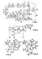
- the pre-circuit and pre-amplifier circuit is shown in FIG. 2 without taking into account the first range switch 2.
- the pre-circuit filter accordingly consists of the series connection of three frequency-determining coils 30, 31, 32, to which a common frequency-determining capacitor 33 is connected in parallel, preferably in the form of a voltage-controllable capacitance diode.
- the first coil 30 is connected on one side to ground potential and the third coil 32 is connected to the input 14 of the preamplifier 15 via an isolating capacitor 34.
- a range switch 35 parallel to the series connection of the second and third coils 31 and 32, there is a range switch 35, which is designed in particular as a switching diode that can be controlled by direct current.
- An adaptation coil 37 leads from the connection point 36 between the second and the third coil 31 or 32 to the antenna connection 1.
- the pre-circuit filter 12 is dimensioned for the low frequency range, which ranges from approximately 50 to 150 MHz. Within this frequency range, the adaptation coil 37 is largely ineffective, particularly at the low frequencies.
- the basic adaptation takes place here through the division ratio of the inductance values of the coils 30, 31 and 32.
- the capacitance variation of the capacitor 33 allows the low frequency range in which all three coils 30, 31 and 32 are frequency-determining to be tuned.
- a correction capacitor 38 can be connected in parallel to the range switch 35, which corrects the effective variation range of the capacitor 33 when the range switch (35) is open limited.
- the range switch (35) thus serves at the same time to change the tuning ratio.
- the coil 30 alone is connected directly in parallel to the capacitor 33 and thus determines the high frequency range.
- the correction capacitor 38 is also short-circuited, and with it the capacitor 33 its entire variation range alone determines the frequency.
- the series connection of the coils 31 and 32 also becomes a parallel connection which is in series with the matching coil 37.
- the coils 31, 32 and 37 then together serve to adapt the pre-circuit filter circuit to the characteristic impedance of the antenna line, it then being possible to change the inductance value of the adaptation coil 37 for the adjustment. This change has practically no effect in the lower frequency range.
- a change in the inductance value of the coil 30 which may have to be carried out for the adjustment of the resonant circuit has only a minor influence on the oscillation frequency of the entire resonant circuit in the lower frequency range, because the inductance value of the coil 30 is small in comparison to the total inductance value of the coils 31 and 32.
- This pre-circuit circuit also only requires a common preamplifier 15, so that a frequency range switchover, a change in the tuning ratio and a switchover of the adaptation in the frequency ranges take place with only one range switch 35. For this minimal number of components, only a correspondingly small space in the tuner housing is required without adversely affecting the selection, the tuning range and the interference immunity.
- the switching device 17 for the band filters 19 and 21 is connected to the output 16 of the preamplifier 15, the switching device having a capacitor 39 which is connected from the output 16 to the input 20 of the band filter 21 for the high frequency range.
- a coil 40 leads from the output 16 via the parallel connection from a high-frequency choke 41 and a band switch 42 to a power supply source 46 or via a low-pass capacitor 43 to the input 18 of the band filter 19 for the low frequency range.
- the band switch 42 like the high-frequency choke 41, is connected to ground potential in high frequency via a blocking capacitor 47. When the band switch 42 is closed, which is preferably also a switching diode and is controlled together with the range switch 35, the high-pass capacitor 39 with the high-pass coil 40 forms a bandpass for the high frequency range, the
- Connection point 45 of the coil 40 is connected to the capacitor 43 via the band switch 42 to ground potential.
- the band filter for the low frequency range is thus high frequency, input side and short-circuited.
- the high-pass filter 39, 40 thus enables an optimal adaptation between the preamplifier 15 and the band filter 21.
- the coil 40 forms a low-pass filter with the capacitor 43, through the capacitor 39, via which the input impedance of the band filter 21 is grounded, for the low frequency range, with the band filter 19 that is connected still coupled via the capacitor 39 Band filter 21 for the high frequency range so largely detuned that a selection of certain frequencies is no longer possible there.
- the high-frequency choke 41 provides a direct current path to the output 16 of the amplifier 15 when the band switch 42 is open, so that the amplifier element present in the preamplifier 15 can be supplied with direct current without influencing the low-pass filter via this path.
- FIG. 4 shows a circuit arrangement according to FIG. 3, in which a switching diode 42 is used as the band switch.
- a simple diode 47 is provided, via which the DC power is supplied to the preamplifier 15 when the low frequency range is to be switched on.
- the switching diode 42 is de-energized and therefore blocked, that is, the range switch is open. If, in contrast, the switching diode 42 is switched on to the direct current source 46, the current flowing through it causes the switching through, as a result of which the band switch is closed.
- the circuit arrangement is then switched over for the high frequency range after the connection point 45 is then connected to ground potential via the switching diode 42 and the associated blocking capacitor 44.1.
- the switching diode 42 or the band switch is neither in a frequency-determining resonant circuit nor in the high-frequency path from the preamplifier 15 to the bandpass filters 19, 21, so that it does not have any adverse effects on the selection and the tunable bandwidth.
Landscapes
- Channel Selection Circuits, Automatic Tuning Circuits (AREA)
- Superheterodyne Receivers (AREA)
- Filters And Equalizers (AREA)
- Input Circuits Of Receivers And Coupling Of Receivers And Audio Equipment (AREA)
Applications Claiming Priority (2)
| Application Number | Priority Date | Filing Date | Title |
|---|---|---|---|
| DE3821716 | 1988-06-28 | ||
| DE3821716A DE3821716A1 (de) | 1988-06-28 | 1988-06-28 | Fernsehtuner mit einer bandfilterschaltung |
Publications (2)
| Publication Number | Publication Date |
|---|---|
| EP0348680A2 true EP0348680A2 (fr) | 1990-01-03 |
| EP0348680A3 EP0348680A3 (fr) | 1990-05-16 |
Family
ID=6357389
Family Applications (1)
| Application Number | Title | Priority Date | Filing Date |
|---|---|---|---|
| EP89109901A Withdrawn EP0348680A3 (fr) | 1988-06-28 | 1989-06-01 | Tuner pour télévision avec circuit filtre passe-bande |
Country Status (4)
| Country | Link |
|---|---|
| US (1) | US5122878A (fr) |
| EP (1) | EP0348680A3 (fr) |
| JP (1) | JP2810881B2 (fr) |
| DE (1) | DE3821716A1 (fr) |
Cited By (1)
| Publication number | Priority date | Publication date | Assignee | Title |
|---|---|---|---|---|
| GB2251147A (en) * | 1990-10-01 | 1992-06-24 | Motorola Inc | Filter switching circuit |
Families Citing this family (21)
| Publication number | Priority date | Publication date | Assignee | Title |
|---|---|---|---|---|
| US5402138A (en) * | 1991-05-30 | 1995-03-28 | Conifer Corporation | Integrated MMDS/MDS antenna and dual band down converter |
| US5437052A (en) * | 1993-04-16 | 1995-07-25 | Conifer Corporation | MMDS over-the-air bi-directional TV/data transmission system and method therefor |
| SG55266A1 (en) * | 1997-01-15 | 1999-04-27 | Koninkl Philips Electronics Nv | Multi-tuner receiver |
| JPH11127086A (ja) * | 1997-08-19 | 1999-05-11 | Alps Electric Co Ltd | Uhf及びvhf共用チューナ |
| JP3183332B2 (ja) * | 1997-09-30 | 2001-07-09 | 日本電気株式会社 | テレビチューナ、チューナic、テレビチューナの制御方法 |
| US6246866B1 (en) * | 1998-12-04 | 2001-06-12 | Motorola, Inc. | Dual band receiver |
| US7068329B1 (en) * | 1999-08-31 | 2006-06-27 | Ati International Srl | Method and system for providing a video signal |
| EP1156582A3 (fr) * | 2000-05-16 | 2004-04-28 | Nokia Corporation | Optimalisation d'impédance d'une chaíne de transmission et de réception |
| DE10102201C2 (de) * | 2001-01-18 | 2003-05-08 | Epcos Ag | Elektrisches Schaltmodul, Schaltmodulanordnung und verwendung des Schaltmoduls und der Schaltmodulanordnung |
| JP2002280911A (ja) * | 2001-03-19 | 2002-09-27 | Nec Corp | 送信回路及びそれを搭載した通信端末 |
| US20050059371A1 (en) * | 2001-09-28 | 2005-03-17 | Christian Block | Circuit arrangement, switching module comprising said circuit arrangement and use of switching module |
| US7343137B2 (en) * | 2001-09-28 | 2008-03-11 | Epcos Ag | Circuit, switching module comprising the same, and use of said switching module |
| US7492565B2 (en) * | 2001-09-28 | 2009-02-17 | Epcos Ag | Bandpass filter electrostatic discharge protection device |
| DE10246098A1 (de) | 2002-10-02 | 2004-04-22 | Epcos Ag | Schaltungsanordnung |
| DE10300892A1 (de) * | 2003-01-13 | 2004-07-22 | Deutsche Thomson-Brandt Gmbh | Schaltbares abstimmbares Bandfilter mit optimiertem Frequenzgang |
| JP3106226U (ja) * | 2004-06-28 | 2004-12-16 | アルプス電気株式会社 | テレビジョンチューナ |
| JP2007068143A (ja) * | 2005-08-05 | 2007-03-15 | Matsushita Electric Ind Co Ltd | アンテナ整合器とこれを用いた高周波受信装置 |
| US9793935B2 (en) * | 2015-07-02 | 2017-10-17 | Mediatek Inc. | Multi-mixer system and method for reducing interference within multi-mixer system |
| EP3403327A1 (fr) | 2016-01-15 | 2018-11-21 | Telefonaktiebolaget LM Ericsson (publ.) | Filtres accordables miniatures |
| US10419749B2 (en) | 2017-06-20 | 2019-09-17 | Ethertronics, Inc. | Host-independent VHF-UHF active antenna system |
| CN115568089B (zh) * | 2022-10-09 | 2025-11-21 | 合肥工业大学 | 一种可重构四种微波功能的无源有源混合电路 |
Family Cites Families (26)
| Publication number | Priority date | Publication date | Assignee | Title |
|---|---|---|---|---|
| DE2412689C3 (de) * | 1974-03-16 | 1978-04-27 | Philips Patentverwaltung Gmbh, 2000 Hamburg | Schaltungsanordnung zur Abstimmung und Bereichs- bzw. Bandumschaltung eines HF-Schwingungskreises |
| US3962643A (en) * | 1974-08-05 | 1976-06-08 | Zenith Radio Corporation | Abrupt junction varactor diode television tuner |
| JPS5823978B2 (ja) * | 1975-11-11 | 1983-05-18 | ソニー株式会社 | チユ−ナ |
| DE2828838C2 (de) * | 1977-07-01 | 1983-10-20 | Hitachi, Ltd., Tokyo | HF-Eingangsschaltung für Fernsehempfänger |
| JPS5413205A (en) * | 1977-07-01 | 1979-01-31 | Hitachi Ltd | Automatic channel tuner |
| GB2000926B (en) * | 1977-07-05 | 1982-04-28 | Texas Instruments Inc | Channel selector for television receiver |
| GB2058505B (en) * | 1977-07-05 | 1982-09-15 | Texas Instruments Inc | Channel selector for a television receiver |
| JPS6046895B2 (ja) * | 1978-08-04 | 1985-10-18 | アルプス電気株式会社 | 電子同調チユ−ナ |
| US4419768A (en) * | 1980-09-30 | 1983-12-06 | Matsushita Electric Industrial Company, Limited | Wideband tuner for VHF, CATV and UHF television signals |
| JPS5816944U (ja) * | 1981-07-27 | 1983-02-02 | 日本電気ホームエレクトロニクス株式会社 | Vhf電子チユ−ナ |
| US4408348A (en) * | 1981-08-19 | 1983-10-04 | Rca Corporation | Multiband tuning system for a television receiver |
| DE3144390A1 (de) * | 1981-11-07 | 1983-05-19 | Licentia Patent-Verwaltungs-Gmbh, 6000 Frankfurt | Schwingkreisschaltung |
| US4418427A (en) * | 1982-03-30 | 1983-11-29 | Rca Corporation | Tuning system for a multi-band television receiver |
| US4470071A (en) * | 1982-08-30 | 1984-09-04 | Rca Corporation | Television sound detection system using a frequency translation phase-locked loop |
| JPS5959032U (ja) * | 1982-10-13 | 1984-04-17 | アルプス電気株式会社 | 同調回路 |
| DE3507865A1 (de) * | 1985-03-06 | 1986-09-11 | Philips Patentverwaltung Gmbh, 2000 Hamburg | Schaltungsanordnung fuer einen tuner zur umschaltung mehrerer frequenzbereiche |
| DE3509517A1 (de) * | 1985-03-16 | 1986-09-25 | Philips Patentverwaltung Gmbh, 2000 Hamburg | Schaltungsanordnung fuer einen tuner zur umschaltung zweier frequenzbaender |
| DE3509516C1 (de) * | 1985-03-16 | 1986-09-18 | Philips Patentverwaltung Gmbh, 2000 Hamburg | Schaltungsanordnung der Eingangsstufen eines Fernsehtuners |
| DE3538921A1 (de) * | 1985-11-02 | 1987-05-14 | Telefunken Electronic Gmbh | Fernsehtuner |
| JPS62209910A (ja) * | 1986-03-11 | 1987-09-16 | Matsushita Electric Ind Co Ltd | 帯域消去ろ波器 |
| JPS62152519U (fr) * | 1986-03-19 | 1987-09-28 | ||
| JPH0510412Y2 (fr) * | 1986-04-02 | 1993-03-15 | ||
| JPS6326124U (fr) * | 1986-07-31 | 1988-02-20 | ||
| JPS6352510A (ja) * | 1986-08-22 | 1988-03-05 | Toshiba Corp | 電子同調チユ−ナ |
| GB2196197B (en) * | 1986-10-01 | 1990-09-19 | Telefunken Electronic Gmbh | Television tuner |
| DE3633384A1 (de) * | 1986-10-01 | 1988-04-14 | Telefunken Electronic Gmbh | Fernsehtuner fuer drei unterschiedliche frequenzbereiche |
-
1988
- 1988-06-28 DE DE3821716A patent/DE3821716A1/de active Granted
-
1989
- 1989-06-01 EP EP89109901A patent/EP0348680A3/fr not_active Withdrawn
- 1989-06-20 US US07/368,540 patent/US5122878A/en not_active Expired - Fee Related
- 1989-06-27 JP JP1162838A patent/JP2810881B2/ja not_active Expired - Fee Related
Cited By (2)
| Publication number | Priority date | Publication date | Assignee | Title |
|---|---|---|---|---|
| GB2251147A (en) * | 1990-10-01 | 1992-06-24 | Motorola Inc | Filter switching circuit |
| GB2251147B (en) * | 1990-10-01 | 1994-10-26 | Motorola Inc | Filter switching circuit |
Also Published As
| Publication number | Publication date |
|---|---|
| DE3821716C2 (fr) | 1990-11-29 |
| DE3821716A1 (de) | 1990-01-04 |
| EP0348680A3 (fr) | 1990-05-16 |
| JP2810881B2 (ja) | 1998-10-15 |
| US5122878A (en) | 1992-06-16 |
| JPH0258415A (ja) | 1990-02-27 |
Similar Documents
| Publication | Publication Date | Title |
|---|---|---|
| EP0348680A2 (fr) | Tuner pour télévision avec circuit filtre passe-bande | |
| DE2828838C2 (de) | HF-Eingangsschaltung für Fernsehempfänger | |
| EP0195480B1 (fr) | Montage de circuit pour un circuit d'accord pour la commutation de deux bandes de fréquence | |
| EP0818888B1 (fr) | Filtre passe-bande commutable pour tuner multi-gammes | |
| DE3606437C2 (fr) | ||
| DE3875661T2 (de) | Fernseh-hf-eingangsschaltung. | |
| EP0126340A2 (fr) | Circuit d'entrée avec au moins deux voies d'entrée | |
| DE3633384C2 (fr) | ||
| DE19734265A1 (de) | Fernsehtuner | |
| EP0193995B1 (fr) | Agencement de circuit pour un tuner pour la commutation de plusieurs bandes de fréquence | |
| EP0348697A2 (fr) | Tuner pour télévision | |
| EP0196130B1 (fr) | Montage de circuit pour étage d'entrée d'un circuit d'accord d'un récepteur de télévision | |
| DE10300892A1 (de) | Schaltbares abstimmbares Bandfilter mit optimiertem Frequenzgang | |
| EP0091169B1 (fr) | Filtre passe-bande à deux circuits résonnants pour sélecteurs de canaux | |
| DE3311640C2 (fr) | ||
| DE3538921C2 (fr) | ||
| DE3689704T2 (de) | Steuerbarer Oszillator. | |
| DE19715956C2 (de) | Eingangsschaltung für einen Fernsehtuner | |
| DE2503785C3 (de) | Kombituner für die Frequenzbereiche UHF und VHF | |
| EP0348698B1 (fr) | Circuit d'entrée d'un tuner pour récepteur de télévision | |
| EP0128532A2 (fr) | Circuit d'accord pour UHF and VHF | |
| DE19639238C2 (de) | Eingangsabstimmkreis für Fernsehgerät | |
| DE3144390A1 (de) | Schwingkreisschaltung | |
| DE3144242C2 (fr) | ||
| DE1616297B2 (de) | UHF-VHF-Abstimmschaltung mit Bereichsumschaltung |
Legal Events
| Date | Code | Title | Description |
|---|---|---|---|
| PUAI | Public reference made under article 153(3) epc to a published international application that has entered the european phase |
Free format text: ORIGINAL CODE: 0009012 |
|
| AK | Designated contracting states |
Kind code of ref document: A2 Designated state(s): DE FR GB IT NL |
|
| PUAL | Search report despatched |
Free format text: ORIGINAL CODE: 0009013 |
|
| AK | Designated contracting states |
Kind code of ref document: A3 Designated state(s): DE FR GB IT NL |
|
| 17P | Request for examination filed |
Effective date: 19901102 |
|
| RAP1 | Party data changed (applicant data changed or rights of an application transferred) |
Owner name: TEMIC TELEFUNKEN MICROELECTRONIC GMBH |
|
| 17Q | First examination report despatched |
Effective date: 19950914 |
|
| GRAG | Despatch of communication of intention to grant |
Free format text: ORIGINAL CODE: EPIDOS AGRA |
|
| GRAH | Despatch of communication of intention to grant a patent |
Free format text: ORIGINAL CODE: EPIDOS IGRA |
|
| STAA | Information on the status of an ep patent application or granted ep patent |
Free format text: STATUS: THE APPLICATION IS DEEMED TO BE WITHDRAWN |
|
| 18D | Application deemed to be withdrawn |
Effective date: 19970303 |