EP0347875A2 - Gewebebahnherstellung mit zwei ineinandergreifenden Walzen - Google Patents
Gewebebahnherstellung mit zwei ineinandergreifenden Walzen Download PDFInfo
- Publication number
- EP0347875A2 EP0347875A2 EP89111282A EP89111282A EP0347875A2 EP 0347875 A2 EP0347875 A2 EP 0347875A2 EP 89111282 A EP89111282 A EP 89111282A EP 89111282 A EP89111282 A EP 89111282A EP 0347875 A2 EP0347875 A2 EP 0347875A2
- Authority
- EP
- European Patent Office
- Prior art keywords
- web
- disks
- machine
- driving
- retarding
- Prior art date
- Legal status (The legal status is an assumption and is not a legal conclusion. Google has not performed a legal analysis and makes no representation as to the accuracy of the status listed.)
- Withdrawn
Links
Images


Classifications
-
- D—TEXTILES; PAPER
- D06—TREATMENT OF TEXTILES OR THE LIKE; LAUNDERING; FLEXIBLE MATERIALS NOT OTHERWISE PROVIDED FOR
- D06C—FINISHING, DRESSING, TENTERING OR STRETCHING TEXTILE FABRICS
- D06C23/00—Making patterns or designs on fabrics
- D06C23/04—Making patterns or designs on fabrics by shrinking, embossing, moiréing, or crêping
-
- B—PERFORMING OPERATIONS; TRANSPORTING
- B31—MAKING ARTICLES OF PAPER, CARDBOARD OR MATERIAL WORKED IN A MANNER ANALOGOUS TO PAPER; WORKING PAPER, CARDBOARD OR MATERIAL WORKED IN A MANNER ANALOGOUS TO PAPER
- B31F—MECHANICAL WORKING OR DEFORMATION OF PAPER, CARDBOARD OR MATERIAL WORKED IN A MANNER ANALOGOUS TO PAPER
- B31F1/00—Mechanical deformation without removing material, e.g. in combination with laminating
- B31F1/12—Crêping
- B31F1/122—Crêping the paper being submitted to an additional mechanical deformation other than crêping, e.g. for making it elastic in all directions
Definitions
- This invention relates to a machine and method for processing webs in which the web is longitudinally compressed under the influence of driving forces provided by two rotating rolls and retarding forces applied by stationary members.
- the two rolls are themselves corrugated and the roll corrugations are mated such that the paper, when passed through the nip, becomes corrugated.
- Lorenz U.S. Patent 1,689,037, shows a pair of mated serrated rolls for corrugating paper, followed by a pair of guide bars defining a corrugated channel through which the paper passes on its way to a pair of creping rolls.
- a web is creped by passing it into the nip between two drive rolls each having disks alternating with spacer elements.
- the disks of one roll may be offset relative to the other roll.
- the web After passing through a relatively long confining passage, the web is engaged by slower rotating rolls which cause the web to crowd together in the long passage to form transverse crepes.
- the long passage is bounded by two sets of long, thin members, the forward ends of which are tapered and disposed in the spaces between the disks of the drive rolls.
- Molla U.S. Patent 2,814,332 shows a paper-forming machine in which two serrated rolls with toothed lands impress a pattern on the web and a set of fingers interdigitated in the valleys of the lower roll strip the web off the lower roll.
- the invention can be employed to impart highly desirable properties, especially permanent softness, to webs.
- the invention features a machine and process that employs two side-by-side sets of spaced apart driven disks adapted to rotate respectively in opposite directions about two spaced apart parallel axes, the axes being sufficiently close that peripheral margins of the disks of one set run between the peripheral margins of the disks of the other set in a mated relationship, the sets of disks mutually defining a series of web driving regions spaced apart in a direction parallel with the axes, with successive driving regions off-set from one another and open channels between the disks providing, with the driving regions, a width-wise continuous non-linear cross section corridor through which the web passes, the driving regions adapted to impart to a web led lengthwise into the corridor, crosswise tension in the web, pulling the web about the edges of the disks, the tension enabling the disks to apply forward driving force to the web and retarding means closely disposed to the driving regions to apply retarding forces on the web in the region of the corridor, the retarding forces opposing the driving forces to produce immediate, continual longitudinal shortening of the
- Preferred embodiments of the invention include the following features.
- Means following the retarding means applies tension in the machine direction to pull out compaction produced by the retarding means.
- Smaller diameter segments alternate with the disks along the axis of each roll.
- the disks are all of the same diameter.
- Each disk bears a non-friction driving surface
- the web is stretched width-wise as it passes through the corridor. Both rolls rotate at the same angular velocity.
- the web is a hard-surfaced material.
- the web has a high tensile strength in the directions of both its width and length.
- the web is building-wrap material formed of hot-colendared, spun bonded fibers and the shortening produced is pulled out to create a softened or more pliable web.
- the retarding means has retarding fingers; each finger lies opposite one of the disks to apply a retarding force on one face of the web while an opposing driving force is applied by the disk to the opposite web face.
- the fingers present convexly curved surfaces to the faces of the web.
- the processed web is substantially softer than the unprocessed web with the softness not being lost by the action of plastic memory, even after a long period of time.
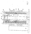
- a continuous dense web 12 is led from a supply roll (not shown) over a guide roll 14 into the meshed region 15 between two drive rolls 16, 18 that are driven at the same speed in opposite directions (as indicated by arrows 19).
- a pair of retarders 20, 22 are positioned to retard the motion of web 12 in a manner to be described below.
- the web 40 is tensioned by controlled dancer roll 47 and led to driven takeup roll 49.
- Retarders 20, 22 are respectively held in brackets 24, 26 which are in turn mounted respectively on supports 28, 30. Each support 28, 30 is held in place at one end by being mounted rotatably on a shaft 32, 34 of one of the rolls 16, 18, and at the other end by a supporting rod 36, 38.
- Rods 36, 38 occupy fixed positions during a processing run but their lengths (and hence the precise positions of retarders 20, 22 relative to the nip region) can be adjusted by a conventional adjustment mechanism (not shown).
- the ends of rods 36, 38 are threaded and removably held to the frame 37 by nuts 39, 41. By removing the nuts, the rods can be released from the frame and the retarders pulled away from region 15 for servicing.
- Rod 38 holds a pneumatic cylinder 43 supplied by a pressure line 45, thus supporting rod 38 resiliently.
- rolls 16, 18 are driven at a selected speed by a conventional motor and driving mechanism 42 mounted on frame 37.
- Rolls 16, 18 are supported in a metal frame 46 (also mounted on frame 37) with the axes of the two rolls parallel.
- the vertical spacing between the two rolls can be adjusted by conventional means (not shown) but the spacing between them is generally held fixed during a processing run.
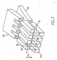
- Each roll 16, 18 is milled to form a set of identical, spaced apart larger diameter (4") disks 50 alternated with a set of identical segments 52 of somewhat smaller diameter (3 5/8").
- each roll 16, 18 thus presents a series of alternating lands (formed by the peripheral walls of the larger disks 50) and valleys (formed by the peripheral walls of the smaller segments 52).
- Rolls 16, 18 are axially offset relative to one another to enable these lands and valleys to be mated, that is with the lands of roll 16 nestled to a limited extent in the valleys of roll 18 and the valleys of roll 16 nestled in the lands of roll 18.
- the peripheral margins of the disks 50 of roll 16 run between the peripheral margins of the disks 50 of roll 18.
- a pair of plates 54, 56 is adjustably mounted on a rod 58 attached to frame 46.
- the width of the opening between plates 54, 56 can then be adjusted to accommodate the width of web 12.
- Each plate 54, 56 is narrow enough to slip between adjacent disks 50 to position the web.
- Rolls 16, 18 contain conventional electric heating elements (not shown) that can be controlled to bring the rolls to a desired even temperature appropriate for processing the particular web being used.
- the machine of Fig. 2 is modified in having a pair of enlarged disks 50e and 50e′, on roll 16′, one of which, 50e, is shown nestled in an end-most valley V of the matin, roll 18′.
- roll 16′ is axially adjustable, as well as being movable away from roll 18′.
- the machine is readily set up for mated operation by adjusting roll 16′ axially until enlarged disk 50e registers with vally V, and enters valley V upon adjustment of the rolls together. This assures registry of all the other disks with their valleys.
- the other enlarged disk 50e′ when it enters valley V′, ensures that the disks are matched in direct opposition with respect to one another, to operate according to a different matched mode of treatment, in which pairs of disks form drive rings to drive the web and pairs of retarders match to form retarding cavities to retard the web.
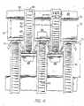
- each of the two retarders 20, 22 is cut from a sheet of 0.125" thick metal to form a row of parallel evenly spaced retarder fingers 70.
- Each finger 70 has a convexly curved contact surface 72 that contacts one face of the web and an end face 73 that is substantially perpendicular to the plane of the web.
- the width a of each finger 70 e.g., 0.090
- the width b of the space between adjacent fingers 70 e.g., 0.060" are such that successive fingers 70 nest within successive valleys along the corresponding roll 16, 18 with the lands of the roll positioned in the spaces b.
- the two retarders are offset laterally with respect to one another so that each finger on retarder 20 lies above an inter-finger space of retarder 22.
- Each finger 70 also has a surface 75, parallel to surface 72, which, during operation, faces (but does not bear against) the peripheral surface (85 in Fig. 4) of the smaller diameter segment associated with that finger.
- Each retarder 20, 22 is attached to its associated bracket 24, 26 by conventional means.
- Each retarder 20, 22 is rolled to have a curvature of radius of about 4" along the length from retarding face 72 to the brackets 24, 26, with the two retarders curving away from each other towards their bracketed ends.
- Fingers 70 being of cantilever form, are resiliently deformable in the direction indicated by arrows 77 under the influence of operating conditions.
- each finger 70 has a thickness c (e.g., 0.125") that is considerably smaller than the depth d (e.g., 3/8") of the valley in which it nests.
- Each larger diameter disk 50 is machined to have a central peripheral driving track 80.
- the total width w d of disk 50 is, e.g., 0.050
- the width w e of the track 80 is between 0.025" and slightly less than 0.050" (e.g., .045")
- the total space g between tracks is between 0.100" and 0.150" (e.g., 0.110").
- Track 80 is cylindrical, its surface is parallel to the roll axes 32, 34 (Fig.
- a radially oriented open channel 89 joins each pair of adjacent driving regions, so that the driving regions and joining channels together form a corridor of non-linear cross section in the direction of the width of the web through which the web 12 extends.
- the retarders 20, 22 are positioned at the outfeed end to resist the motion of web 12.
- the convex surface of each finger 70 contacts the web for retarding. As adjusted as shown in Fig. 5 the fingers extend past the line of centers of the rolls, while contact with the web is made on the opposite face of the web from the face touching a land, at a position only slightly downstream of the position of maximum drive by the disk. In another condition of adjustment, forward extensions of the fingers may serve as stationary driving shoes, pressing the web into engagement with the disks, to enhance the forward drive of the web.
- the longitudinal compression of web 12 occurs in a short length region 99 beginning approximately at the line of centers of the two rolls (at plane 96, on which the roll shafts 32, 34 lie) and ending at a point a short distance (i.e., a distance far shorter than the radius of the rolls 16, 18) on the outfeed side.
- region 99 will depend on the thickness of the web being processed and on the fineness of the microcreping desired. A thicker web will require a greater distance and a shorter distance will produce a finer microcrepe. The best distance for a particular web and desired treatment is determined by trial of a number of different settings.
- the spacing between the contact faces of opposing retarder teeth may have been temporarily reduced by the resilience of the fingers or their mounting. That spacing can be opened up to its normal running size either by a tool or simply by driving the web into region 15; in that case the web itself will force open the teeth.
- the spacing between the roll axes must be adjusted (by nuts 39, 41, Fig. 1). In general, the correct adjustment is determined by increasing the spacing while feeding the web until the web is no longer longitudinally cut by the action of the driving rolls. Note that the width-wise corridor in which the web lies is not a traditional nip because each land is not opposed by a closely spaced corresponding land such that the web is pinched between and driven by them.
- the driving force 92 is opposed by a retarding force 96 imparted by a retarding tooth 70.
- a retarding tooth is located at every position along the width of the web; thus the driving action is opposed at all positions along the web but alternately on opposite faces of the web.
- the retarders cause the web to be longitudinally compacted in a series of microcrepes 98. The microcreping occurs within a short distance on the outfeed side of the driving locations.
- the untreated web is a hard material, e.g., Tyvek (available from DuPont)
- Tyvek available from DuPont
- the combination of width-wise stretching and longitudinal compaction alters the web fibers in a way that produces a softer processed web.
- the plastic memory that is normally associated with certain web materials and causes them, over time, to return to their pre-processed condition, is effectively minimized, giving the processed web a long shelf life during which its softness does not diminish.
- the process is particularly useful with webs that demonstrate considerable widthwise tensional strength and is particularly appropriate where it is desired to disrupt fiber-to-fiber bonds to render the web softer and more easily draped or wrapped about objects.
- the softening action arises through a triangulation of different forces.
- the take up device 47 applies sufficient tension to pull out the microcrepe formations following the retarder means, to restore the web to substantially its orignal width, but in a softened condition.
- the rolls can be of different diameters and driven at different speeds.
- the valleys in one roll can be deeper than the valleys in the other roll.
- the retarder teeth can be provided with a high frictional contact surfaces. Widths of the lands and valleys can be altered. The teeth of the retarders could bear against the peripheral surfaces of the smaller diameter disks.
Landscapes
- Engineering & Computer Science (AREA)
- Textile Engineering (AREA)
- Mechanical Engineering (AREA)
- Treatment Of Fiber Materials (AREA)
- Machines For Manufacturing Corrugated Board In Mechanical Paper-Making Processes (AREA)
- Registering, Tensioning, Guiding Webs, And Rollers Therefor (AREA)
Applications Claiming Priority (2)
| Application Number | Priority Date | Filing Date | Title |
|---|---|---|---|
| US211385 | 1988-06-24 | ||
| US07/211,385 US4921643A (en) | 1988-06-24 | 1988-06-24 | Web processing with two mated rolls |
Publications (2)
| Publication Number | Publication Date |
|---|---|
| EP0347875A2 true EP0347875A2 (de) | 1989-12-27 |
| EP0347875A3 EP0347875A3 (de) | 1990-03-28 |
Family
ID=22786721
Family Applications (1)
| Application Number | Title | Priority Date | Filing Date |
|---|---|---|---|
| EP89111282A Withdrawn EP0347875A3 (de) | 1988-06-24 | 1989-06-21 | Gewebebahnherstellung mit zwei ineinandergreifenden Walzen |
Country Status (5)
| Country | Link |
|---|---|
| US (1) | US4921643A (de) |
| EP (1) | EP0347875A3 (de) |
| JP (1) | JPH0245134A (de) |
| BR (1) | BR8903079A (de) |
| FI (1) | FI893027A7 (de) |
Families Citing this family (29)
| Publication number | Priority date | Publication date | Assignee | Title |
|---|---|---|---|---|
| US5567498A (en) * | 1993-09-24 | 1996-10-22 | Alliedsignal Inc. | Textured ballistic article |
| US5814390A (en) | 1995-06-30 | 1998-09-29 | Kimberly-Clark Worldwide, Inc. | Creased nonwoven web with stretch and recovery |
| US5792487A (en) * | 1996-04-10 | 1998-08-11 | Witt Plastics Of Florida Inc. | Corrugated plastic wall panels |
| US20030234468A1 (en) * | 1997-01-17 | 2003-12-25 | Krishnakumar Rangachari | Soft, absorbent material for use in absorbent articles and process for making the material |
| US6485667B1 (en) | 1997-01-17 | 2002-11-26 | Rayonier Products And Financial Services Company | Process for making a soft, strong, absorbent material for use in absorbent articles |
| US6074526A (en) * | 1997-08-18 | 2000-06-13 | Fort James Corporation | Method of creping tissue |
| CA2248727C (en) | 1997-12-19 | 2007-08-14 | Kimberly-Clark Worldwide, Inc. | Mechanical softening of sheet material |
| USD419780S (en) * | 1998-11-04 | 2000-02-01 | Kimberly-Clark Worldwide, Inc. | Embossed tissue |
| US6323388B1 (en) * | 1998-11-04 | 2001-11-27 | Kimberly-Clark Worldwide, Inc. | Absorbent article with an improved, wet-formed absorbent |
| USD415353S (en) | 1998-11-04 | 1999-10-19 | Kimberly-Clark Worldwide, Inc. | Embossed tissue |
| US6706945B1 (en) | 1998-11-04 | 2004-03-16 | Kimberly-Clark Worldwide, Inc. | Absorbent article with improved, wet-formed absorbent |
| USD419779S (en) * | 1998-11-04 | 2000-02-01 | Kimberly-Clark Worldwide, Inc. | Embossed tissue |
| USD417962S (en) * | 1998-11-04 | 1999-12-28 | Kimberly-Clark Worldwide, Inc. | Embossed tissue |
| US6214274B1 (en) | 1999-05-14 | 2001-04-10 | Kimberly-Clark Worldwide, Inc. | Process for compressing a web which contains superabsorbent material |
| US6491777B1 (en) * | 1999-12-07 | 2002-12-10 | Polymer Goup, Inc. | Method of making non-woven composite transfer layer |
| TW200300185A (en) * | 2001-11-07 | 2003-05-16 | Procter & Gamble | Textured materials and method of manufacturing textured materials |
| US7175727B2 (en) | 2002-08-30 | 2007-02-13 | Kimberley-Clark Worldwide, Inc. | Shaped absorbent pads and associated method for making |
| US7419570B2 (en) * | 2002-11-27 | 2008-09-02 | Kimberly-Clark Worldwide, Inc. | Soft, strong clothlike webs |
| US7182837B2 (en) | 2002-11-27 | 2007-02-27 | Kimberly-Clark Worldwide, Inc. | Structural printing of absorbent webs |
| US6964726B2 (en) * | 2002-12-26 | 2005-11-15 | Kimberly-Clark Worldwide, Inc. | Absorbent webs including highly textured surface |
| US7021414B2 (en) * | 2003-03-25 | 2006-04-04 | Wayne Campbell | Birdcage bearing assembly and suspension connection for a high performance vehicle |
| US7858544B2 (en) | 2004-09-10 | 2010-12-28 | First Quality Nonwovens, Inc. | Hydroengorged spunmelt nonwovens |
| US7651653B2 (en) | 2004-12-22 | 2010-01-26 | Kimberly-Clark Worldwide, Inc. | Machine and cross-machine direction elastic materials and methods of making same |
| WO2007120629A2 (en) | 2006-04-10 | 2007-10-25 | First Quality Nonwovens, Inc. | Cotendered nonwoven/pulp composite fabric and method for making the same. |
| US20070254058A1 (en) * | 2006-05-01 | 2007-11-01 | Wade A B | Systems and methods for forming polymeric sheets |
| US9446163B2 (en) | 2010-08-20 | 2016-09-20 | First Quality Nonwovens, Inc. | Nonwoven having improved softness signals, and methods for manufacturing |
| US10639212B2 (en) | 2010-08-20 | 2020-05-05 | The Procter & Gamble Company | Absorbent article and components thereof having improved softness signals, and methods for manufacturing |
| US9446537B1 (en) * | 2011-11-09 | 2016-09-20 | Beijing Apollo Ding Rong Solar Technology Co., Ltd. | Methods and apparatuses for cutting of thin film solar cells |
| US9649792B2 (en) | 2013-10-15 | 2017-05-16 | Velcro BVBA | Forming longitudinally pleated products |
Family Cites Families (69)
| Publication number | Priority date | Publication date | Assignee | Title |
|---|---|---|---|---|
| DE127110C (de) * | ||||
| DE130463C (de) * | ||||
| DD91122A (de) * | ||||
| US1702166A (en) * | 1929-02-12 | Paper-crinkling machine | ||
| US1447699A (en) * | 1923-03-06 | Paper-crinkling mechanism | ||
| US623695A (en) * | 1899-04-25 | James arkell | ||
| US739276A (en) * | 1902-05-12 | 1903-09-22 | Walter L Allen | Machine for corrugating paper. |
| US1295636A (en) * | 1917-10-26 | 1919-02-25 | Scott Paper Co | Means for making paper. |
| US1548783A (en) * | 1919-12-20 | 1925-08-04 | Otaka Fabric Company | Apparatus for and method of making crinkled fabric |
| US1554246A (en) * | 1920-01-19 | 1925-09-22 | Arkell Safety Bag Co | Apparatus for making stretchable paper |
| US1630320A (en) * | 1920-03-18 | 1927-05-31 | Arkell Safety Bag Co | Paper-creping apparatus |
| US1627966A (en) * | 1920-04-17 | 1927-05-10 | Arkell Safety Bag Co | Apparatus for operating on paper and other fabrics |
| US1550084A (en) * | 1920-09-03 | 1925-08-18 | Otaka Fabric Company | Paper-crinkling machine |
| US1582839A (en) * | 1920-11-05 | 1926-04-27 | Otaka Fabric Company | Paper-crinkling machine |
| US1582840A (en) * | 1920-11-05 | 1926-04-27 | Otaka Fabric Company | Paper crinkling |
| US1582841A (en) * | 1921-01-04 | 1926-04-27 | Otaka Fabric Company | Paper corrugating |
| US1548788A (en) * | 1921-02-16 | 1925-08-04 | Otaka Fabric Company | Paper crinkling |
| US1548789A (en) * | 1921-05-18 | 1925-08-04 | Otaka Fabric Company | Paper-crinkling machine |
| US1571594A (en) * | 1921-08-05 | 1926-02-02 | Otaka Fabric Company | Paper embossing |
| US1680203A (en) * | 1924-04-07 | 1928-08-07 | William H Cannard | Crepe and method of and apparatus for making the same |
| US1582842A (en) * | 1924-08-11 | 1926-04-27 | Otaka Fabric Company | Elastic paper |
| US1582843A (en) * | 1924-08-20 | 1926-04-27 | Otaka Fabric Company | Apparatus for crinkling paper |
| US1764676A (en) * | 1924-12-20 | 1930-06-17 | Samuel J Campbell | Creping machine |
| US1601633A (en) * | 1925-07-31 | 1926-09-28 | Otaka Fabric Company | Paper-crinkling machine |
| US1676655A (en) * | 1927-02-02 | 1928-07-10 | Otaka Fabric Company | Paper-making machine |
| US1686388A (en) * | 1927-03-18 | 1928-10-02 | Otaka Fabric Company | Paper-crinkling machine |
| US1689037A (en) * | 1927-04-02 | 1928-10-23 | Otaka Fabric Company | Machine for making elastic paper |
| US1667292A (en) * | 1927-04-09 | 1928-04-24 | Otaka Fabric Company | Machine for making elastic paper |
| US1690172A (en) * | 1927-04-09 | 1928-11-06 | Lorenz Phoebe Bunker | Machine for making elastic paper |
| US1690411A (en) * | 1927-05-21 | 1928-11-06 | Hudson David William | Creping of paper |
| US1701685A (en) * | 1927-05-28 | 1929-02-12 | Otaka Fabric Company | Machine for making elastic paper |
| US1680797A (en) * | 1927-07-16 | 1928-08-14 | Otaka Fabric Company | Paper-crinkling apparatus |
| US1751471A (en) * | 1929-05-04 | 1930-03-25 | Hudson Sharp Machine Co | Creping mechanism |
| DE727763C (de) * | 1936-06-16 | 1942-11-11 | Ernst Bernstein | Maschine zum Laengskreppen von Papier o. dgl. |
| US2245014A (en) * | 1936-08-29 | 1941-06-10 | American Reenforced Paper Co | Stretchable paper |
| US2224713A (en) * | 1937-08-19 | 1940-12-10 | Paper Service Co | Creped and corrugated web |
| US2196006A (en) * | 1937-12-10 | 1940-04-02 | Elb Products Inc | Machine and process for plaiting |
| US2425207A (en) * | 1940-02-19 | 1947-08-05 | Cincinnati Ind Inc | Creping corrugated papers |
| US2623572A (en) * | 1949-05-25 | 1952-12-30 | Waldhof Zellstoff Fab | Apparatus for creping paper |
| GB752191A (en) * | 1952-01-19 | 1956-07-04 | Bleachers Ass Ltd | Improvements in or relating to ornamentation of sheet materials |
| US2793418A (en) * | 1953-08-06 | 1957-05-28 | Bachmann Uxbridge Worsted Corp | Crimping of filaments |
| US2814332A (en) * | 1954-07-12 | 1957-11-26 | Fiammiferi Ed Affiui Spa Fab | Machine for manufacturing formed paper |
| US2851206A (en) * | 1954-08-03 | 1958-09-09 | Bancroft & Sons Co J | Random pleating of fabric |
| DE1018716B (de) * | 1954-10-22 | 1957-10-31 | Waldhof Zellstoff Fab | Verfahren und Vorrichtung zur Erzeugung von Laengswellen in einer laufenden Materialbahn |
| DE1093659B (de) * | 1956-05-28 | 1960-11-24 | Richard Rohdes Walton | Einrichtung zum Querkreppen oder -stauchen einer fortlaufenden Bahn folienfoermigen Materials |
| US3022545A (en) * | 1956-09-06 | 1962-02-27 | British Celanese | Process for crimping cellulose triacetate fibers |
| US2938568A (en) * | 1956-11-27 | 1960-05-31 | Arkell Safety Bag Co | Machine for and method of corrugating paper |
| US2915109A (en) * | 1957-05-07 | 1959-12-01 | Richard R Walton | Condensing traveling sheet materials |
| US2917784A (en) * | 1957-06-05 | 1959-12-22 | Dow Chemical Co | Crimping fibers |
| US2958608A (en) * | 1958-04-18 | 1960-11-01 | Chicopee Mfg Corp | Textile fabrics and methods of making the same |
| US3220056A (en) * | 1959-11-27 | 1965-11-30 | Richard R Walton | Treatment of sheet materials |
| US3260778A (en) * | 1964-01-23 | 1966-07-12 | Richard R Walton | Treatment of materials |
| US3390218A (en) * | 1964-10-06 | 1968-06-25 | Johnson & Johnson | Method of pleating sheet materials |
| CH439199A (de) * | 1964-07-18 | 1967-07-15 | Beckers Gustav | Vorrichtung zum kontinuierlichen Stauchen flacher Warenbahnen |
| US3383449A (en) * | 1964-10-01 | 1968-05-14 | Muller Paul Adolf | Method for producing an endless filter string |
| US3353222A (en) * | 1965-01-22 | 1967-11-21 | Eastman Kodak Co | Textile crimping |
| US3400193A (en) * | 1965-07-15 | 1968-09-03 | Dow Chemical Co | Process for preparing filamentary microtapes of labyrinthian cross section |
| DE1816028C3 (de) * | 1968-12-20 | 1982-06-09 | Vepa AG, 4125 Riehen, Basel | Vorrichtung zum Kräuseln von synthetischen Fadenscharen |
| DE1955196A1 (de) * | 1969-11-03 | 1971-05-06 | Vepa Ag | Vorrichtung zum Stauchen von textilen Wirk- und Webwaren |
| CH529856A (de) * | 1970-08-10 | 1972-10-31 | Vepa Ag | Vorrichtung zum Kräuseln synthetischer Fadenscharen |
| US3806406A (en) * | 1971-12-20 | 1974-04-23 | Beloit Corp | Tissue former including a yankee drier having raised surface portions |
| FR2276914A1 (fr) * | 1974-07-04 | 1976-01-30 | Kroyer St Annes Ltd Karl | Appareil de moulage |
| US4142278A (en) * | 1976-10-29 | 1979-03-06 | Richard R. Walton | Compressive treatment of web materials |
| US4090385A (en) * | 1977-01-26 | 1978-05-23 | Bird Machine Company, Inc. | Material treating apparatus |
| WO1981000082A1 (en) * | 1979-06-28 | 1981-01-22 | Tilburg R | Creping machine and method |
| CA1167627A (en) * | 1980-08-05 | 1984-05-22 | George E. Munchbach | Longitudinal compressive treatment method and apparatus for web materials |
| US4422892A (en) * | 1981-05-04 | 1983-12-27 | Scott Paper Company | Method of making a bonded corrugated nonwoven fabric and product made thereby |
| EP0176566A4 (de) * | 1984-03-29 | 1988-06-08 | Richard R Walton | Bandbearbeitung bei längszusammendrückung. |
| NO874838L (no) * | 1986-11-20 | 1988-05-24 | Richard R Walton | Maskin for komprimering av en bane i dens lengderetning. |
-
1988
- 1988-06-24 US US07/211,385 patent/US4921643A/en not_active Expired - Fee Related
-
1989
- 1989-06-20 FI FI893027A patent/FI893027A7/fi not_active Application Discontinuation
- 1989-06-21 EP EP89111282A patent/EP0347875A3/de not_active Withdrawn
- 1989-06-23 BR BR898903079A patent/BR8903079A/pt unknown
- 1989-06-26 JP JP1163615A patent/JPH0245134A/ja active Pending
Also Published As
| Publication number | Publication date |
|---|---|
| JPH0245134A (ja) | 1990-02-15 |
| FI893027A0 (fi) | 1989-06-20 |
| US4921643A (en) | 1990-05-01 |
| BR8903079A (pt) | 1990-02-06 |
| EP0347875A3 (de) | 1990-03-28 |
| FI893027A7 (fi) | 1989-12-25 |
Similar Documents
| Publication | Publication Date | Title |
|---|---|---|
| US4921643A (en) | Web processing with two mated rolls | |
| JP3548594B2 (ja) | ウエブ材料のログを製造するとともに各ログの巻取り完了時にウエブ材料を切断する方法および装置 | |
| US3564677A (en) | Method and apparatus of treating material to change its configuration | |
| US2290608A (en) | Foil crumpling method and apparatus | |
| US3466358A (en) | Method of making filtering material for cigarettes | |
| US4247273A (en) | Method and an apparatus for cambering the edges of webs of thermoplastic materials on one and both sides using the energy of ultrasonic vibration | |
| ES2176822T3 (es) | Un aparato para formar laminas de material de espesor uniforme y cortar prociones del material. | |
| US3220056A (en) | Treatment of sheet materials | |
| US3887419A (en) | Apparatus and method for continuously forming honeycomb material | |
| US3220057A (en) | Treatment of sheet materials | |
| KR19990071899A (ko) | 서로 다른 회전속도를 가진 엠보싱실린더가 설치된 엠보싱 및라미네이팅기계 | |
| US3425888A (en) | Method and apparatus for producing faced corrugated materials | |
| US5220858A (en) | Method and apparatus for forming scored lines on sheet material | |
| US4859169A (en) | Web processing by longitudinal compression using matched drive disks and retarding fingers | |
| IL27273A (en) | Mechanical compactment of materials | |
| US3188372A (en) | Machine and method for compacting materials | |
| CN1240402A (zh) | 弯折料段的装置 | |
| EP0403089A2 (de) | Vorrichtung und Verfahren zum Einkerben von Blättern | |
| US4086687A (en) | Apparatus for relaxing or loosening needled textile fabrics | |
| US1560670A (en) | Straightening and stretching machine | |
| US4432926A (en) | Method and apparatus for imparting two-way properties to flexible webs | |
| JP3551714B2 (ja) | 異形断面条の矯正方法 | |
| JPH01264800A (ja) | 連続用紙切り離し方法及び装置 | |
| EP0268304A2 (de) | Maschine und Verfahren zur Bearbeitung von Bahnen mittels longitudinalen Zusammendrückens | |
| JPH0375662B2 (de) |
Legal Events
| Date | Code | Title | Description |
|---|---|---|---|
| PUAI | Public reference made under article 153(3) epc to a published international application that has entered the european phase |
Free format text: ORIGINAL CODE: 0009012 |
|
| AK | Designated contracting states |
Kind code of ref document: A2 Designated state(s): AT BE CH DE ES FR GB GR IT LI LU NL SE |
|
| PUAL | Search report despatched |
Free format text: ORIGINAL CODE: 0009013 |
|
| AK | Designated contracting states |
Kind code of ref document: A3 Designated state(s): AT BE CH DE ES FR GB GR IT LI LU NL SE |
|
| 17P | Request for examination filed |
Effective date: 19900720 |
|
| 17Q | First examination report despatched |
Effective date: 19920330 |
|
| STAA | Information on the status of an ep patent application or granted ep patent |
Free format text: STATUS: THE APPLICATION IS DEEMED TO BE WITHDRAWN |
|
| 18D | Application deemed to be withdrawn |
Effective date: 19930706 |