EP0347740A1 - Thermal recording head - Google Patents
Thermal recording head Download PDFInfo
- Publication number
- EP0347740A1 EP0347740A1 EP89110836A EP89110836A EP0347740A1 EP 0347740 A1 EP0347740 A1 EP 0347740A1 EP 89110836 A EP89110836 A EP 89110836A EP 89110836 A EP89110836 A EP 89110836A EP 0347740 A1 EP0347740 A1 EP 0347740A1
- Authority
- EP
- European Patent Office
- Prior art keywords
- pressing
- heat
- thermal head
- support
- heating
- Prior art date
- Legal status (The legal status is an assumption and is not a legal conclusion. Google has not performed a legal analysis and makes no representation as to the accuracy of the status listed.)
- Withdrawn
Links
- 238000003825 pressing Methods 0.000 claims abstract description 63
- 238000010438 heat treatment Methods 0.000 claims abstract description 39
- 239000000463 material Substances 0.000 claims abstract description 12
- 238000000034 method Methods 0.000 claims description 27
- 238000001816 cooling Methods 0.000 claims description 15
- 238000002844 melting Methods 0.000 claims description 3
- 230000008018 melting Effects 0.000 claims description 2
- 238000010008 shearing Methods 0.000 description 8
- 239000000835 fiber Substances 0.000 description 3
- 239000000203 mixture Substances 0.000 description 3
- 230000002250 progressing effect Effects 0.000 description 3
- 239000011347 resin Substances 0.000 description 3
- 229920005989 resin Polymers 0.000 description 3
- 239000011800 void material Substances 0.000 description 3
- 239000000853 adhesive Substances 0.000 description 1
- 230000001070 adhesive effect Effects 0.000 description 1
- 230000002411 adverse Effects 0.000 description 1
- 239000006229 carbon black Substances 0.000 description 1
- 230000007423 decrease Effects 0.000 description 1
- 230000002542 deteriorative effect Effects 0.000 description 1
- 230000000694 effects Effects 0.000 description 1
- 238000011156 evaluation Methods 0.000 description 1
- ZXQYGBMAQZUVMI-GCMPRSNUSA-N gamma-cyhalothrin Chemical compound CC1(C)[C@@H](\C=C(/Cl)C(F)(F)F)[C@H]1C(=O)O[C@H](C#N)C1=CC=CC(OC=2C=CC=CC=2)=C1 ZXQYGBMAQZUVMI-GCMPRSNUSA-N 0.000 description 1
- 231100000989 no adverse effect Toxicity 0.000 description 1
- 239000000049 pigment Substances 0.000 description 1
- -1 polyethylene terephthalate Polymers 0.000 description 1
- 229920000139 polyethylene terephthalate Polymers 0.000 description 1
- 239000005020 polyethylene terephthalate Substances 0.000 description 1
- 239000000126 substance Substances 0.000 description 1
Images
Classifications
-
- B—PERFORMING OPERATIONS; TRANSPORTING
- B41—PRINTING; LINING MACHINES; TYPEWRITERS; STAMPS
- B41J—TYPEWRITERS; SELECTIVE PRINTING MECHANISMS, i.e. MECHANISMS PRINTING OTHERWISE THAN FROM A FORME; CORRECTION OF TYPOGRAPHICAL ERRORS
- B41J2/00—Typewriters or selective printing mechanisms characterised by the printing or marking process for which they are designed
- B41J2/315—Typewriters or selective printing mechanisms characterised by the printing or marking process for which they are designed characterised by selective application of heat to a heat sensitive printing or impression-transfer material
- B41J2/32—Typewriters or selective printing mechanisms characterised by the printing or marking process for which they are designed characterised by selective application of heat to a heat sensitive printing or impression-transfer material using thermal heads
- B41J2/335—Structure of thermal heads
- B41J2/33505—Constructional details
- B41J2/33535—Substrates
-
- B—PERFORMING OPERATIONS; TRANSPORTING
- B41—PRINTING; LINING MACHINES; TYPEWRITERS; STAMPS
- B41J—TYPEWRITERS; SELECTIVE PRINTING MECHANISMS, i.e. MECHANISMS PRINTING OTHERWISE THAN FROM A FORME; CORRECTION OF TYPOGRAPHICAL ERRORS
- B41J2/00—Typewriters or selective printing mechanisms characterised by the printing or marking process for which they are designed
- B41J2/315—Typewriters or selective printing mechanisms characterised by the printing or marking process for which they are designed characterised by selective application of heat to a heat sensitive printing or impression-transfer material
- B41J2/32—Typewriters or selective printing mechanisms characterised by the printing or marking process for which they are designed characterised by selective application of heat to a heat sensitive printing or impression-transfer material using thermal heads
- B41J2/335—Structure of thermal heads
- B41J2/33555—Structure of thermal heads characterised by type
- B41J2/3357—Surface type resistors
Definitions
- This invention relates to a heat-sensitive recording method and a thermal head. More specifically, it relates to heat sensitive recording method and thermal head which can print at high speed with excellent printing quality even onto a recording member with rough surface.
- heat sensitive recording method using thermal head, etc. to transfer the heat sensitive recording media (or ink material) to transfer media such as recording paper, etc. have been widely employed.
- a part of the ink layer of the heat-sensitive recording medium is heated by the above-decribed dot printing unit and is transferred to the transfer medium under pressure applied at the same time and then the supporting member of the heat-sensitive recording medium is separated, thereby the above-described part is transferred to the transfer medium.
- thermo head which is designed so that the above-described part is separated from the supporting means as quickly as possible by positioning the dot printing unit of the thermal head near the edge of the board, a thermal head positioned at a certain inclination angle to the transfer medium to increase the platen pressure, a thermal head in which a double glaze layer is formed projecting on the surface opposing to the heat-sensitive recording medium of the board and a heat resistant element is provided at the top of the double glaze layer, etc.
- the part to be transferred is pressed strongly under pressure by the dot printing unit itself provided with a heat resistant element, and when pressed, the part to be transferred has been melted with very little cohesive power unable to hold its form so that bridging transfer onto the concave-convex parts of the transfer medium becomes impossible, in addition, a crushed image is formed, melted ink soaks into paper fiber when the transfer medium is paper, and resultantly, paper fiber may come up to the surface from the image. Furthermore, void or blur may result or stain of the base or trailing by the high temperature dot printing unit may result when it is pressed.
- a heat sensitive recording medium with such an ink layer which has high cohesive power even at the time of transfer to the transfer medium should be used and resultantly, shearing property at the border between the heated part to be transferred and an ink layer which has not been heated decreases due to the high cohesive power of the ink layer, deteriorating the printing sharpness.
- This invention was made based on the above conditions.
- the object of this invention is to provide heat-sensitive recording method and thermal head which can print with less generation of void, blur, trailing, stain of the base, etc. even for transfer media of low surface smoothness, not to mention transfer medium of high surface smoothness, with high printing quality and especially at high speed.
- the invention to solve the above-described problems relates to a heat-sensitive recording method in which thermal energy is supplied by the heat-generating unit of the thermal head to a part of the heat-sensitive recording medium to melt the above-described part to be transferred, and then the part to be transferred in the cooling process after being melted is pressed by force larger than that of the above described heat-generating unit by a pressing unit provided in a position other than the above-described heat generating unit, and the invention to solve the above described problem provides a thermal head in which a pressing unit which can press the heat-sensitive transfer recording medium by force larger than that of the above-described heat-generating unit is provided at a position other than the heat-generating unit which supplies thermal energy to the part to be transferred of the heat sensitive recording medium.
- the principle of this invention is that an ink layer of a heat-sensitive recording medium is melted by supplying heat enough to melt this ink layer, the melted ink layer is placed in the cooling process to make it have proper cohesive power, proper adhesive strength to the transfer medium, and proper shearing property to an ink layer which has not been heated, and the said ink layer is pressed to the transfer medium by force larger than the pressing force at the supplying time of thermal energy to the transfer medium.
- thermal energy is supplied to the part to be transferred of the heat-sensitive recording medium.
- the ink layer should be melted instantaneously when this thermal energy is supplied. It is enough if the ink layer placed in the cooling process after being melted is pressed. Therefore, the ink layer may be melted immediately by the heating unit or may be melted after the part to be transferred heated by the heating unit has moved from the heating unit.
- the heat energy volume or amount to be supplied to the part to be transferred should be enough at least to melt the ink layer of the transfer layer but cannot be determined indiscriminately since it varies depending on the types of the supporting member of the heat-sensitive recording medium, its thickness, and composition and thickness of the ink layer, and other conditions. In other words, the thermal energy volume may be determined properly according to above-described various factors.
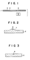
- the part to be transferred of the heat-sensitive recording medium is the part of the ink layer 3 of the heat-sensitive recording medium 1 in Fig. 1 which is heated by the heat-generating unit 5 and melted.
- the heat-generating unit 5 may be of any form and structure if it can supply thermal energy to the ink layer of the heat-sensitive recording medium and melt it.
- a projection 7 may be formed on the board 6 of the thermal head and heat resistant element 8 may be provided at the top of the projection 7, or at a position slightly out of the top on the side of the projection 7, or as shown in Fig. 3, heat resistant element 8 may be embedded in the board 6 of the thermal head.
- the above-described heat-sensitive recording medium 1 usually has at least the supporting member 2 and ink layer 3.
- paper, resin film, laminated film comprising paper and resin film, metallic sheet, etc. may be used as a supporting member 2.
- the ink layer 3 usually contains at least a heat-melting substance and carbon black or other color pigments.
- the ink layer 3 may be one layer or multiple layers more than two.
- heat-sensitive recording medium is unlimited and may be a tape, ribbon or sheet, for example.
- the part to be transferred of this heat-sensitive recording medium is heated and melted by the above-described heat-generating unit, and the heat-generating unit may bring the melted part to be transferred in pressure contact with the above-described transfer medium.
- the object of this invention can be attained if the part to be transferred is pressed in the process to cool the melted ink layer with apressing force larger than that in the heating process, pressing the part to be transferred by the heating unit does not present any adverse effect.
- the part to be transferred may not be adhered to the transfer medium or moved due to the small cohesive power, and if the ink layer is not melted even if the heating unit heats it, the good adhesiveness for the transfer medium may not be revealed in the ink layer, therefore pressing by the heating unit for transfer offers no adverse effect either from this point of view.
- thermal energy is supplied to the part to be transferred of the heat-sensitive recording medium and the ink layer melted by it is subjected to a cooling process and the above-described part to be transferred in the cooling process after being melted is pressed by the force larger than that of the above-described heat-generating part.
- the pressing part is placed at a place different from the above-described heating part because the ink layer which is heated and melted by the above-described heating part is pressed in the cooling process.
- the heating part and pressing part are desirably positioned with each other so that in the cooling process they are pressed under proper cohesive power, with proper adhesiveness to the transfer medium, and good shearing property from an ink layer which is not heated.
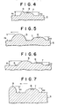
- the thermal head in Fig. 4 is formed by projecting the pressing part 9 on the side of the projecting part 7 which projects from the surface of the board 6 and is provided with the heat resistant element 8 on the top.
- the height H1 of the pressing part 9 above the plane of the board 6 is determined to be larger than the height H2 of the top of the above-described projecting part 7 above the plain of the board 6.
- the pressing part 9 is separated from the heat-generating resistance element 8.
- the thermal head in Fig. 5 is formed by projecting the pressing part 9 between the projecting part 7 which projects from the surface of the board 7 and is provided with the heat resistance element 8 on the top and the edge of the thermal head in the relative progressing direction (arrow mark in the figure) of the heat-sensitive recording medium.
- the height H1 of the pressing part 9 above the plain of the board 6 is determined to be larger than the height H2 of the top of the above-described projecting part 7 above the plain of the board 6.
- the thermal head in Fig. 6 is composed of the pressing part projecting adjacent to the projecting part 7 which projects above the surface of the board 6 and is provided with the heat resistant element 8 on the top.
- the height H1 of the pressing part 9 above the plain of the board 6 is determined to be larger than the height H2 of the top of the above-described projecting part 7 above the plain of the board 6.
- the thermal head in Fig. 7 comprises the projecting part 7 which projects from the surface of the board 6 and is provided with the heat resistant element 8 on the top and the pressing part 9 formed projecting at the edge of the thermal head in the relative progressing direction arrow mark in the figure) of the heat-sensitive recording medium.
- the height H1 of the pressing part 9 above the plain of the board 6 is determined to be larger than the height H2 of the pressing part 9 above the plain of the board 6.
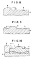
- the thermal head in Fig. 8 is composed in the same way as the thermal head in Fig. 7 except that the heat resistance element 8 is embedded in the board and the heat resistant element 8 is formed without projecting from the plain of the board or being recessed.
- the thermal head in Fig. 9 is composed in the same way as the thermal head in Fig. 5 except that the heat resistant element 8 is embedded in the board and the heat resistant element 8 is formed without projecting from the plain of the board or being recessed.
- the thermal head in Fig. 10 comprises the projecting part 7 which projects from the surface of the board 6 and is provided with the heat resistance element 8 on the top and the pressing part 9 provided at the edge of the heat radiating plate 10 provided to the board 6 to radiate the heat generated at the heat resistant element 8 in the relative progressing direction (arrow mark direction in the figure) of the heat-sensitive recording medium.
- the pressing part has a height H1 extending higher than the height H2 of the above-described projecting part 7.
- a part of the heat radiating plate forms the pressing part. Therefore, such a thermal head is advantageous when the ink layer heated and melted by the heating part is subjected to the cooling process but has not been cooled sufficiently to have proper cohesive power, adhesiveness or shearing property. That is, when pressed, the above-decribed heat radiating plate can remove excessive heat of the ink layer and cool it forcedly to be provided with proper cohesive power, adhesiveness or shearing property. Therefore, for example, the pressing part shown in Fig. 10 serves as a heat absorbing means to absorb the heat from the above-described part to be transferred in the cooling process after melting.
- the heating unit and pressing units are positioned separately from each other and the pressing force of the pressing unit is larger than that of the heating part. It cannot be determined indiscriminately how to separate the heating unit and pressing unit. Usually, it is desirable to determine the distance a between the heat generating part and pressing part to satisfy the equation (1) with respect to the relation with the printing speed s. 0.1 m sec. ⁇ a/s ⁇ 160 m sec.
- the ink layer which is melted once by the heating part moves to the cooling process and presents proper cohesive power, adhesiveness or shearing property, it is timely pressed to the transfer medium and it is desirable to provide a heat supply means for the pressing part when the ink layer is cooled excessively at the time of pressing in the cooling proccess depending on the contents of the compositions comprising the ink layer or for some other reasons.
- the heat supply means is not limited specifically and may be a heat resistant element, etc.
- the heat supplied to the ink layer by this heat supply means is enough to provide proper cohesive power, adhesiveness or shearing property for the ink layer.
- Actual value of the heat is determined depending on the composition of the ink layer, time from the heating part to the pressing part, etc.
- an image is formed on the recording member according to the method of this invention and using the thermal head according to this invention.
- the transfer medium there are no specific restrictions and any forms and materials may be used such as normal or other papers, OHP sheet or other resin sheets, of high surface smoothness or low surface smoothness such as rough paper, etc.
- This invention is to ensure high printing quality by controlling the nature of the ink layer at the time of transfer irrespective of the surface condition of the transfer medium and is not related with the condition of the transfer medium.
- Embodiments of this invention are described below. Printing was made using a heat-sensitive recording means comprising an ink layer of 4 ⁇ m in thickness on a polyethylene terephthalate film of 3.5 ⁇ m in thickness.
- An energy applied to the head was 30 mJ/head, printing speed was 90 cps, the platen pressure of the printer was 700 g/head and for the recording member having rough surface, TROJAN BONG paper was used.
- a heat-sensitive recording method which can print at high speed with excellent printing quality even for transfer media of low surface smoothness can be provided.
- thermal heads with the following advantages can be provided:
Landscapes
- Electronic Switches (AREA)
- Thermal Transfer Or Thermal Recording In General (AREA)
Applications Claiming Priority (2)
| Application Number | Priority Date | Filing Date | Title |
|---|---|---|---|
| JP63154021A JPH024576A (ja) | 1988-06-22 | 1988-06-22 | 感熱記録方法およびサーマルヘッド |
| JP154021/88 | 1988-06-22 |
Publications (1)
| Publication Number | Publication Date |
|---|---|
| EP0347740A1 true EP0347740A1 (en) | 1989-12-27 |
Family
ID=15575172
Family Applications (1)
| Application Number | Title | Priority Date | Filing Date |
|---|---|---|---|
| EP89110836A Withdrawn EP0347740A1 (en) | 1988-06-22 | 1989-06-14 | Thermal recording head |
Country Status (3)
| Country | Link |
|---|---|
| US (1) | US4973987A (ja) |
| EP (1) | EP0347740A1 (ja) |
| JP (1) | JPH024576A (ja) |
Cited By (2)
| Publication number | Priority date | Publication date | Assignee | Title |
|---|---|---|---|---|
| EP1557275A3 (en) * | 2004-01-26 | 2009-03-04 | Alps Electric Co., Ltd. | Thermal head |
| CN110461614A (zh) * | 2017-03-29 | 2019-11-15 | 京瓷株式会社 | 热敏头及热敏打印机 |
Families Citing this family (3)
| Publication number | Priority date | Publication date | Assignee | Title |
|---|---|---|---|---|
| US5266970A (en) * | 1992-08-05 | 1993-11-30 | Eastman Kodak Company | Hot bar fuser |
| US6025860A (en) * | 1997-01-28 | 2000-02-15 | Gsi Lumonics, Inc. | Digital decorating system |
| JP6364379B2 (ja) * | 2015-05-07 | 2018-07-25 | アオイ電子株式会社 | サーマルヘッド |
Citations (4)
| Publication number | Priority date | Publication date | Assignee | Title |
|---|---|---|---|---|
| EP0194528A2 (en) * | 1985-03-15 | 1986-09-17 | Hitachi, Ltd. | Printer having a thermal head |
| DE3614840A1 (de) * | 1985-05-01 | 1986-11-06 | Alps Electric Co., Ltd., Tokio/Tokyo | Thermodrucker mit korrektur-moeglichkeit |
| DE3721925A1 (de) * | 1986-07-02 | 1988-01-07 | Mitsubishi Electric Corp | Thermisches umdruckverfahren |
| US4746933A (en) * | 1985-12-28 | 1988-05-24 | Canon Kabushiki Kaisha | Thermal record-erase head |
Family Cites Families (7)
| Publication number | Priority date | Publication date | Assignee | Title |
|---|---|---|---|---|
| JPS5749579A (en) * | 1980-09-08 | 1982-03-23 | Rohm Co Ltd | Thermal printer head |
| JPS59120473A (ja) * | 1982-12-28 | 1984-07-12 | Rohm Co Ltd | サ−マルプリンタヘツド |
| JPS6068972A (ja) * | 1983-09-27 | 1985-04-19 | Seiko Epson Corp | サ−マルプリンタヘツド |
| US4712637A (en) * | 1985-06-20 | 1987-12-15 | Honda Giken Kogyo Kabushiki Kaisha | Straddle type vehicle seat assembly |
| US4725835A (en) * | 1985-09-13 | 1988-02-16 | T-Bar Incorporated | Time multiplexed bus matrix switching system |
| JPS62208958A (ja) * | 1986-03-10 | 1987-09-14 | Alps Electric Co Ltd | サ−マルプリンタ |
| JPS63114676A (ja) * | 1986-10-31 | 1988-05-19 | Mitsubishi Electric Corp | サ−マルプリンタ |
-
1988
- 1988-06-22 JP JP63154021A patent/JPH024576A/ja active Pending
-
1989
- 1989-06-12 US US07/365,087 patent/US4973987A/en not_active Expired - Fee Related
- 1989-06-14 EP EP89110836A patent/EP0347740A1/en not_active Withdrawn
Patent Citations (4)
| Publication number | Priority date | Publication date | Assignee | Title |
|---|---|---|---|---|
| EP0194528A2 (en) * | 1985-03-15 | 1986-09-17 | Hitachi, Ltd. | Printer having a thermal head |
| DE3614840A1 (de) * | 1985-05-01 | 1986-11-06 | Alps Electric Co., Ltd., Tokio/Tokyo | Thermodrucker mit korrektur-moeglichkeit |
| US4746933A (en) * | 1985-12-28 | 1988-05-24 | Canon Kabushiki Kaisha | Thermal record-erase head |
| DE3721925A1 (de) * | 1986-07-02 | 1988-01-07 | Mitsubishi Electric Corp | Thermisches umdruckverfahren |
Cited By (4)
| Publication number | Priority date | Publication date | Assignee | Title |
|---|---|---|---|---|
| EP1557275A3 (en) * | 2004-01-26 | 2009-03-04 | Alps Electric Co., Ltd. | Thermal head |
| CN110461614A (zh) * | 2017-03-29 | 2019-11-15 | 京瓷株式会社 | 热敏头及热敏打印机 |
| EP3587125A4 (en) * | 2017-03-29 | 2020-03-18 | Kyocera Corporation | THERMAL HEAD AND THERMAL PRINTER |
| CN110461614B (zh) * | 2017-03-29 | 2021-02-05 | 京瓷株式会社 | 热敏头及热敏打印机 |
Also Published As
| Publication number | Publication date |
|---|---|
| JPH024576A (ja) | 1990-01-09 |
| US4973987A (en) | 1990-11-27 |
Similar Documents
| Publication | Publication Date | Title |
|---|---|---|
| JPH05169692A (ja) | 熱転写印刷方法 | |
| EP0194528A2 (en) | Printer having a thermal head | |
| US4973987A (en) | Thermal recording head | |
| EP0217306A2 (en) | Thermal transfer printer | |
| JPS60225777A (ja) | 感熱転写記録用インクリボン | |
| JPH0546315B2 (ja) | ||
| US4762432A (en) | Method of thermal printing | |
| JPS61233587A (ja) | 熱転写インクリボン及びこれを用いた熱転写記録装置 | |
| JPS6157356A (ja) | 熱溶融転写装置 | |
| JP2001205940A (ja) | 熱転写記録媒体 | |
| JPS6172574A (ja) | 熱転写プリンタ | |
| JPH0725173B2 (ja) | 熱転写記録装置 | |
| JPH0550629A (ja) | ダイレクト感熱記録用サーマルヘツド | |
| JPH0546916Y2 (ja) | ||
| JPH1067174A (ja) | 熱転写記録方法並びに熱転写記録媒体及びその製造方法 | |
| JPH01215581A (ja) | 接着性表示体の作成方法 | |
| JPH0725226B2 (ja) | 熱転写印字媒体 | |
| JPS62253489A (ja) | 感熱転写媒体 | |
| JPS61154997A (ja) | 感熱転写材 | |
| JPS6213365A (ja) | 感熱転写記録装置 | |
| JPH01125254A (ja) | 熱転写プリンタ | |
| JPH03199073A (ja) | サーマルプリンタ | |
| JPH02293171A (ja) | 熱転写記録装置 | |
| KR19990040818A (ko) | 열전사 기록매체 | |
| JPH0419176A (ja) | 熱転写方式の磁気インク記録媒体および磁気インク記録装置 |
Legal Events
| Date | Code | Title | Description |
|---|---|---|---|
| PUAI | Public reference made under article 153(3) epc to a published international application that has entered the european phase |
Free format text: ORIGINAL CODE: 0009012 |
|
| AK | Designated contracting states |
Kind code of ref document: A1 Designated state(s): DE FR GB |
|
| 17P | Request for examination filed |
Effective date: 19900618 |
|
| STAA | Information on the status of an ep patent application or granted ep patent |
Free format text: STATUS: THE APPLICATION HAS BEEN WITHDRAWN |
|
| 18W | Application withdrawn |
Withdrawal date: 19911210 |