EP0347375A1 - Drucktastenanordnung in einer Leiterplatte - Google Patents
Drucktastenanordnung in einer Leiterplatte Download PDFInfo
- Publication number
- EP0347375A1 EP0347375A1 EP89810409A EP89810409A EP0347375A1 EP 0347375 A1 EP0347375 A1 EP 0347375A1 EP 89810409 A EP89810409 A EP 89810409A EP 89810409 A EP89810409 A EP 89810409A EP 0347375 A1 EP0347375 A1 EP 0347375A1
- Authority
- EP
- European Patent Office
- Prior art keywords
- circuit board
- snap
- printed circuit
- push button
- spacer
- Prior art date
- Legal status (The legal status is an assumption and is not a legal conclusion. Google has not performed a legal analysis and makes no representation as to the accuracy of the status listed.)
- Granted
Links
- 230000001681 protective effect Effects 0.000 claims abstract description 14
- 125000006850 spacer group Chemical group 0.000 claims abstract description 13
- 239000013039 cover film Substances 0.000 claims description 13
- 239000000463 material Substances 0.000 claims description 2
- 230000005489 elastic deformation Effects 0.000 claims 1
- 239000004020 conductor Substances 0.000 abstract description 4
- 230000006378 damage Effects 0.000 description 4
- 238000003491 array Methods 0.000 description 1
- 239000011230 binding agent Substances 0.000 description 1
- 238000010276 construction Methods 0.000 description 1
- 238000011109 contamination Methods 0.000 description 1
- 239000011888 foil Substances 0.000 description 1
- 238000005286 illumination Methods 0.000 description 1
- 229910000679 solder Inorganic materials 0.000 description 1
- 230000003068 static effect Effects 0.000 description 1
Images
Classifications
-
- H—ELECTRICITY
- H01—ELECTRIC ELEMENTS
- H01H—ELECTRIC SWITCHES; RELAYS; SELECTORS; EMERGENCY PROTECTIVE DEVICES
- H01H13/00—Switches having rectilinearly-movable operating part or parts adapted for pushing or pulling in one direction only, e.g. push-button switch
- H01H13/70—Switches having rectilinearly-movable operating part or parts adapted for pushing or pulling in one direction only, e.g. push-button switch having a plurality of operating members associated with different sets of contacts, e.g. keyboard
- H01H13/7006—Switches having rectilinearly-movable operating part or parts adapted for pushing or pulling in one direction only, e.g. push-button switch having a plurality of operating members associated with different sets of contacts, e.g. keyboard comprising a separate movable contact element for each switch site, all other elements being integrated in layers
-
- H—ELECTRICITY
- H01—ELECTRIC ELEMENTS
- H01H—ELECTRIC SWITCHES; RELAYS; SELECTORS; EMERGENCY PROTECTIVE DEVICES
- H01H2205/00—Movable contacts
- H01H2205/016—Separate bridge contact
- H01H2205/024—Means to facilitate positioning
-
- H—ELECTRICITY
- H01—ELECTRIC ELEMENTS
- H01H—ELECTRIC SWITCHES; RELAYS; SELECTORS; EMERGENCY PROTECTIVE DEVICES
- H01H2209/00—Layers
- H01H2209/01—Increasing rigidity; Anti-creep
-
- H—ELECTRICITY
- H01—ELECTRIC ELEMENTS
- H01H—ELECTRIC SWITCHES; RELAYS; SELECTORS; EMERGENCY PROTECTIVE DEVICES
- H01H2213/00—Venting
- H01H2213/002—Venting with external pressure
-
- H—ELECTRICITY
- H01—ELECTRIC ELEMENTS
- H01H—ELECTRIC SWITCHES; RELAYS; SELECTORS; EMERGENCY PROTECTIVE DEVICES
- H01H2219/00—Legends
- H01H2219/002—Legends replaceable; adaptable
- H01H2219/014—LED
-
- H—ELECTRICITY
- H01—ELECTRIC ELEMENTS
- H01H—ELECTRIC SWITCHES; RELAYS; SELECTORS; EMERGENCY PROTECTIVE DEVICES
- H01H2221/00—Actuators
- H01H2221/064—Limitation of actuating pressure
-
- H—ELECTRICITY
- H01—ELECTRIC ELEMENTS
- H01H—ELECTRIC SWITCHES; RELAYS; SELECTORS; EMERGENCY PROTECTIVE DEVICES
- H01H2221/00—Actuators
- H01H2221/07—Actuators transparent
-
- H—ELECTRICITY
- H01—ELECTRIC ELEMENTS
- H01H—ELECTRIC SWITCHES; RELAYS; SELECTORS; EMERGENCY PROTECTIVE DEVICES
- H01H2227/00—Dimensions; Characteristics
- H01H2227/002—Layer thickness
- H01H2227/006—Spacer
Definitions
- the invention relates to a push button arrangement on a printed circuit board.
- the switch contact is generated via a snap disk which is embedded in a spacer and is protected against external attack by a cover.
- Pushbutton arrangements are known in which the switch contact is generated directly on the conductor tracks of a printed circuit board via a snap disk.
- the circuit board is covered with a spacer, which has recesses for embedding these snap disks.
- a cover film is pulled over the recessed snap disks to secure them in the associated cutouts and to protect them from dirt.
- the contact is actuated by hand in that the snap disk is usually pressed down with a finger through the elastic cover film. In this version, the cover film can be deformed as far as the cavities under the cover film allow.
- arrangements are known in which individual pushbuttons, which are provided with protective caps, are placed as separate switches on the printed circuit board, which necessitates an undesired greater overall height and additional electrical connections, such as solder joints, for example.
- the first-mentioned arrangement is characterized by its low overall height.
- the partially hollow cover film is exposed to enormous loads, which can damage the cover film if the snap disk is not operated in the center or with a pointed object.
- the snap disc can also be plastically deformed. Body contact to the electrical potential of the snap disk is possible through the damaged cover film, which on the one hand can lead to damage to sensitive electronic components due to static charges and on the other hand is unreasonable for the operating personnel.
- the object on which the invention is based is to provide pushbutton fields in printed circuit boards which are protected against mechanical damage and against contact with the electrical potential of the switch contact. According to the invention, this object is achieved in that the spacer consists of the same or similar material as the printed circuit board, and that the snap disk is completely covered by a transparent protective cap.
- the invention thus makes it possible, while maintaining a low overall height, to limit the operational loads on the cover foils and the snap disks in such a way that there are no strains and destruction. This prevents additional contamination of the switch contacts.
- the snap disk is provided with at least two protruding tabs which engage in recesses in the printed circuit board.
- the snap disk can be provided with cutouts and / or the printed circuit board with cutouts for the passage of light.
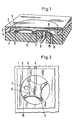
- a pushbutton arrangement is shown in a printed circuit board, which in its basic structure consists of a printed circuit board 1 with printed conductors 6 and a snap disk 5, which rests on the one hand on the printed conductors 6 and on the printed circuit board 1 and on the other hand in its movement from an overlapping one Protective cap 4 is limited, which is held by a cover sheet 3 in a recess of the spacer 2.
- the spacer 2 which is provided with cutouts, consists of a printed circuit board which is fixedly connected to the printed circuit board 1 via a binder and to the cover film 3 on the opposite side.
- the deformation of the cover film 3 and the snap disc 5 is limited by the freedom of movement of the protective cap 4 lying in the recess of the spacer 2.
- the position of the snap disk 5 is secured by two projecting tabs 11 which engage in the recesses 10 of the circuit board 1.
- a light source 9 is attached, which illuminates the protective cap 4 and the cover film 3 through the recess 7 of the circuit board 1 and through the recess 8 on the snap disk 5.
Landscapes
- Push-Button Switches (AREA)
- Switch Cases, Indication, And Locking (AREA)
Abstract
Description
- Die Erfindung bezieht sich auf eine Drucktastenanordnung auf einer Leiterplatte. Bei solchen Anwendungen, wie sie beispielsweise im Schalttafelbau verwendet werden, wird der Schaltkontakt über eine Schnappscheibe erzeugt, die in einem Distanzstück eingebettet ist und durch eine Abdeckung gegen äusseren Angriff geschützt wird.
- Mehrere dieser Drucktastenanordnungen sind im allgemeinen zu Tastenfeldern in Leiterplatten zusammengefasst. Es sind Drucktastenanordnungen bekannt, bei denen der Schaltkontakt über eine Schnappscheibe direkt auf den Leiterbahnen einer Leiterplatte erzeugt wird. Die Leiterplatte ist mit einem Distanzstück belegt, das Aussparungen zum Einbetten dieser Schnappscheiben besitzt. Eine Abdeckfolie ist über die versenkten Schnappscheiben gezogen, um diese in den zugehörigen Aussparungen zu sichern und vor Verschmutzungen zu schützen. Die Betätigung des Kontaktes erfolgt von Hand, indem die Schnappscheibe in der Regel mit einem Finger durch die elastische Abdeckfolie hindurch niedergedrückt wird. Bei dieser Ausführung kann die Abdeckfolie soweit deformiert werden wie es die Hohlräume unter der Abdeckfolie zulassen. Weiterhin sind Anordnungen bekannt, bei denen einzelne Drucktasten, die mit Schutzkappen versehen sind, als separate Schalter auf die Leiterplatte aufgesetzt sind, was eine nicht erwünschte grössere Bauhöhe bedingt und zusätzliche elektrische Verbindungen, wie beispielsweise Lötstellen, bedingt.
- Im Vergleich zu aufgesetzten Einzeltasten zeichnet sich die erstgenannte Anordnung durch geringe Bauhöhe aus. Die teilweise hohlliegende Abdeckfolie ist enormen Belastungen ausgesetzt, die zu Beschädigung der Abdeckfolie führen können, wenn die Betätigung der Schnappscheibe nicht im Zentrum oder mit einem spitzen Gegenstand erfolgt. Ebenso kann die Schnappscheibe plastisch verformt werden. Der Körperkontakt zum elektrischen Potential der Schnappscheibe ist durch die beschädigte Abdeckfolie hindurch möglich, was einerseits wegen statischer Aufladungen zur Schädigung von empfindlichen elektronischen Bauteilen führen kann und andererseits für das Bedienungspersonal nicht zumutbar ist.
- Die der Erfindung zugrundeliegende Aufgabe besteht darin, Drucktastenfelder in Leiterplatten zu schaffen, die gegen mechanische Beschädigung und gegen Berührungskontakt mit dem elektrischen Potential des Schaltkontaktes geschützt sind. Gemäss der Erfindung wird diese Aufgabe dadurch gelöst, dass das Distanzstück aus gleichem oder ähnlichem Material wie die Leiterplatte besteht, und dass die Schnappscheibe vollständig durch eine transparente Schutzkappe abgedeckt ist.
- Somit ermöglicht die Erfindung unter Beibehaltung einer niedrigen Bauhöhe die bedienungsbedingten Belastungen der Abdeckfolien und der Schnappscheiben derart in Grenzen zu halten, dass keine Ueberbeanspruchungen und Zerstörungen auftreten. Dadurch werden zusätzliche Verschmutzungen der Schaltkontakte verhindert.
- Zur Zentrierung der Schnappscheiben, ist es vorteilhaft, wenn die Schnappscheibe mit mindestens zwei vorstehenden Lappen versehen ist, die in Ausnehmungen der Leiterplatte eingreifen.
- Für eine individuelle Beleuchtung der Drucktaste kann man die Schnappscheibe mit Aussparungen und/oder die Leiterplatte mit Ausnehmungen für den Lichtdurchgang versehen.
- Die Verwendung von Leiterplatten gibt die Möglichkeit, die Dicke des Distanzstückes auf grösser 1 mm zu erhöhen und trotz geringer Bauhöhe Schutzkappen einzusetzen.
- Die Erfindung wird im folgenden anhand von einem Ausführungsbeispiel im Zusammenhang mit der Zeichnung näher erläutert.
- Fig. 1 ist schematisch ein Schnitt in perspektivischer Darstellung durch eine erfindungsgemässe Drucktastenanordnung in einer Leiterplatte und
- Fig. 2 ist in verkleinertem Massstab eine Draufsicht ohne Abdeckfolie und ohne Schutzkappe.
- In den Figuren ist eine Drucktastenanordnung in einer Leiterplatte dargestellt, welche in ihrem grundsätzlichen Aufbau aus einer Leiterplatte 1 mit Leiterbahnen 6 und einer Schnappscheibe 5 besteht, die einerseits auf den Leiterbahnen 6 und auf der Leiterplatte 1 aufliegt und die andererseits in ihrer Bewegung von einer überdeckenden Schutzkappe 4 begrenzt ist, die durch eine Abdeckfolie 3 in einer Aussparung des Distanzstückes 2 gehalten wird.
- Erfindungsgemäss besteht das mit Aussparungen versehen Distanzstück 2 aus einer Leiterplatte, die über einen Binder fest mit der Leiterplatte 1 und auf der Gegenseite mit der Abdeckfolie 3 verbunden ist. Die Deformation der Abdeckfolie 3 und der Schnappscheibe 5 ist durch den Bewegungsspielraum der in der Aussparung des Distanzstückes 2 liegenden Schutzkappe 4 begrenzt. Die Lage der Schnappscheibe 5 wird durch zwei vorstehende Lappen 11 gesichert, die in die Ausnehmungen 10 der Leiterplatte 1 eingreifen. Unter der Leiterplatte 1 ist eine Lichtquelle 9 angebracht, die durch die Ausnehmnung 7 der Leiterplatte 1 und durch die Aussparung 8 an der Schnappscheibe 5 die Schutzkappe 4 und die Abdeckfolie 3 erleuchtet.
Claims (7)
Applications Claiming Priority (2)
| Application Number | Priority Date | Filing Date | Title |
|---|---|---|---|
| CH2271/88 | 1988-06-14 | ||
| CH227188A CH676765A5 (de) | 1988-06-14 | 1988-06-14 |
Publications (2)
| Publication Number | Publication Date |
|---|---|
| EP0347375A1 true EP0347375A1 (de) | 1989-12-20 |
| EP0347375B1 EP0347375B1 (de) | 1993-09-15 |
Family
ID=4229866
Family Applications (1)
| Application Number | Title | Priority Date | Filing Date |
|---|---|---|---|
| EP19890810409 Revoked EP0347375B1 (de) | 1988-06-14 | 1989-06-01 | Drucktastenanordnung in einer Leiterplatte |
Country Status (3)
| Country | Link |
|---|---|
| EP (1) | EP0347375B1 (de) |
| CH (1) | CH676765A5 (de) |
| DE (1) | DE58905591D1 (de) |
Cited By (6)
| Publication number | Priority date | Publication date | Assignee | Title |
|---|---|---|---|---|
| DE4213084A1 (de) * | 1992-04-21 | 1993-01-07 | Bock Hans A Dipl Ing Tu | (tast)schalter im lenkrad oder in konsolen, armlehnen etc. zur bedienung durch die "elastische haut" (kunststoff) der oberflaeche |
| EP0538199A3 (en) * | 1991-10-14 | 1993-06-30 | Fela Mikrotechnik Ag | Electrical push botton switch |
| WO1999054900A1 (de) * | 1998-04-18 | 1999-10-28 | Inovan Gmbh & Co. Kg Metalle Und Bauelemente | Schnappscheibenschalter mit befestigungselement |
| WO2000022639A1 (de) * | 1998-10-15 | 2000-04-20 | Gustav Magenwirth Gmbh & Co. | Sprungschalter |
| US6423918B1 (en) * | 2000-03-21 | 2002-07-23 | Lear Corporation | Dome switch |
| EP1465118A3 (de) * | 2003-04-03 | 2005-10-05 | Leopold Kostal GmbH & Co. KG | Fernbedienung zum Betätigen einer Schliesseinrichtung eines Kraftfahrzeuges |
Citations (6)
| Publication number | Priority date | Publication date | Assignee | Title |
|---|---|---|---|---|
| FR2280291A1 (fr) * | 1974-07-24 | 1976-02-20 | Amp Inc | Ensemble electrique a plaque de circuit imprime |
| US4056701A (en) * | 1976-07-08 | 1977-11-01 | Bowmar Instrument Corporation | Low profile lighted push button switch |
| FR2430658A1 (fr) * | 1978-07-07 | 1980-02-01 | Sodeco Compteurs De Geneve | Clavier a boutons-poussoirs |
| FR2447598A1 (fr) * | 1979-01-25 | 1980-08-22 | Itt | Commutateur a bouton poussoir |
| US4365120A (en) * | 1981-04-13 | 1982-12-21 | Kb Denver, Inc. | Illuminated keyboard |
| DE3145434A1 (de) * | 1981-11-16 | 1983-05-26 | Kundisch GmbH, 7730 Villingen-Schwenningen | Folientastatur mit druckpunkt |
-
1988
- 1988-06-14 CH CH227188A patent/CH676765A5/de not_active IP Right Cessation
-
1989
- 1989-06-01 DE DE89810409T patent/DE58905591D1/de not_active Revoked
- 1989-06-01 EP EP19890810409 patent/EP0347375B1/de not_active Revoked
Patent Citations (6)
| Publication number | Priority date | Publication date | Assignee | Title |
|---|---|---|---|---|
| FR2280291A1 (fr) * | 1974-07-24 | 1976-02-20 | Amp Inc | Ensemble electrique a plaque de circuit imprime |
| US4056701A (en) * | 1976-07-08 | 1977-11-01 | Bowmar Instrument Corporation | Low profile lighted push button switch |
| FR2430658A1 (fr) * | 1978-07-07 | 1980-02-01 | Sodeco Compteurs De Geneve | Clavier a boutons-poussoirs |
| FR2447598A1 (fr) * | 1979-01-25 | 1980-08-22 | Itt | Commutateur a bouton poussoir |
| US4365120A (en) * | 1981-04-13 | 1982-12-21 | Kb Denver, Inc. | Illuminated keyboard |
| DE3145434A1 (de) * | 1981-11-16 | 1983-05-26 | Kundisch GmbH, 7730 Villingen-Schwenningen | Folientastatur mit druckpunkt |
Cited By (6)
| Publication number | Priority date | Publication date | Assignee | Title |
|---|---|---|---|---|
| EP0538199A3 (en) * | 1991-10-14 | 1993-06-30 | Fela Mikrotechnik Ag | Electrical push botton switch |
| DE4213084A1 (de) * | 1992-04-21 | 1993-01-07 | Bock Hans A Dipl Ing Tu | (tast)schalter im lenkrad oder in konsolen, armlehnen etc. zur bedienung durch die "elastische haut" (kunststoff) der oberflaeche |
| WO1999054900A1 (de) * | 1998-04-18 | 1999-10-28 | Inovan Gmbh & Co. Kg Metalle Und Bauelemente | Schnappscheibenschalter mit befestigungselement |
| WO2000022639A1 (de) * | 1998-10-15 | 2000-04-20 | Gustav Magenwirth Gmbh & Co. | Sprungschalter |
| US6423918B1 (en) * | 2000-03-21 | 2002-07-23 | Lear Corporation | Dome switch |
| EP1465118A3 (de) * | 2003-04-03 | 2005-10-05 | Leopold Kostal GmbH & Co. KG | Fernbedienung zum Betätigen einer Schliesseinrichtung eines Kraftfahrzeuges |
Also Published As
| Publication number | Publication date |
|---|---|
| CH676765A5 (de) | 1991-02-28 |
| DE58905591D1 (de) | 1993-10-21 |
| EP0347375B1 (de) | 1993-09-15 |
Similar Documents
| Publication | Publication Date | Title |
|---|---|---|
| EP0234193B1 (de) | Schalteranordnung | |
| DE2319042B2 (de) | Tastatur | |
| DE2306268A1 (de) | Tastatur | |
| DE2747425A1 (de) | Flacher schalterfeldaufbau | |
| DE3820430C2 (de) | Tastschalteranordnung für eine flache elektronische Vorrichtung | |
| DE3533719A1 (de) | Schalteranordnung mit einer mehrzahl von bedienelementen | |
| EP0347375A1 (de) | Drucktastenanordnung in einer Leiterplatte | |
| EP1816664A1 (de) | Elektrischer Schalter mit mehreren Schaltrichtungen | |
| DE3643124C2 (de) | ||
| EP0433814B1 (de) | Drucktastenanordnung | |
| DE2923772B2 (de) | Druckschalter an einer photographischen Kamera | |
| DE4022164C2 (de) | ||
| EP0123207B1 (de) | Tastschalteranordnung | |
| DE2844575B1 (de) | Eingabevorrichtung | |
| DE2439697B2 (de) | Druckschalter | |
| DE7920191U1 (de) | Mehrfunktions-Tastenschalter | |
| EP0196633B1 (de) | Tastenkappe für eine in einem Gehäuse angeordnete Tastatur | |
| DE2235898C3 (de) | Vorrichtung zur manuellen Eingabe von Informationen in Datenverarbeitungsgeräte | |
| DE19836793C2 (de) | Bedienelement zum selektiven Herstellen elektrischer Kontakte | |
| DE2452944C3 (de) | Tastenschaltersystem | |
| DE2730659C2 (de) | Tastschalter | |
| EP0119418A2 (de) | Tastschalteinrichtung | |
| DE3504424A1 (de) | Schaltfolientastatur | |
| EP1577916B1 (de) | Schaltereinheit für ein Kraftfahrzeug | |
| DE2612452C3 (de) | Drucktastenschalter |
Legal Events
| Date | Code | Title | Description |
|---|---|---|---|
| PUAI | Public reference made under article 153(3) epc to a published international application that has entered the european phase |
Free format text: ORIGINAL CODE: 0009012 |
|
| AK | Designated contracting states |
Kind code of ref document: A1 Designated state(s): DE FR GB IT |
|
| 17P | Request for examination filed |
Effective date: 19900504 |
|
| 17Q | First examination report despatched |
Effective date: 19920821 |
|
| GRAA | (expected) grant |
Free format text: ORIGINAL CODE: 0009210 |
|
| ITF | It: translation for a ep patent filed | ||
| AK | Designated contracting states |
Kind code of ref document: B1 Designated state(s): DE FR GB IT |
|
| REF | Corresponds to: |
Ref document number: 58905591 Country of ref document: DE Date of ref document: 19931021 |
|
| GBT | Gb: translation of ep patent filed (gb section 77(6)(a)/1977) |
Effective date: 19930924 |
|
| ET | Fr: translation filed | ||
| PGFP | Annual fee paid to national office [announced via postgrant information from national office to epo] |
Ref country code: DE Payment date: 19940514 Year of fee payment: 6 |
|
| PGFP | Annual fee paid to national office [announced via postgrant information from national office to epo] |
Ref country code: GB Payment date: 19940516 Year of fee payment: 6 |
|
| PGFP | Annual fee paid to national office [announced via postgrant information from national office to epo] |
Ref country code: FR Payment date: 19940519 Year of fee payment: 6 |
|
| PLBI | Opposition filed |
Free format text: ORIGINAL CODE: 0009260 |
|
| 26 | Opposition filed |
Opponent name: TEMIC TELEFUNKEN MICROELECTRONIC GMBH Effective date: 19940614 |
|
| RDAG | Patent revoked |
Free format text: ORIGINAL CODE: 0009271 |
|
| STAA | Information on the status of an ep patent application or granted ep patent |
Free format text: STATUS: PATENT REVOKED |
|
| 27W | Patent revoked |
Effective date: 19940923 |
|
| GBPR | Gb: patent revoked under art. 102 of the ep convention designating the uk as contracting state |
Free format text: 940923 |