EP0347076A2 - Aufzeichnungsträger mit ausgerichteter gespannter Oberfläche - Google Patents
Aufzeichnungsträger mit ausgerichteter gespannter Oberfläche Download PDFInfo
- Publication number
- EP0347076A2 EP0347076A2 EP89305593A EP89305593A EP0347076A2 EP 0347076 A2 EP0347076 A2 EP 0347076A2 EP 89305593 A EP89305593 A EP 89305593A EP 89305593 A EP89305593 A EP 89305593A EP 0347076 A2 EP0347076 A2 EP 0347076A2
- Authority
- EP
- European Patent Office
- Prior art keywords
- film
- annular
- recording medium
- support
- principal orientation
- Prior art date
- Legal status (The legal status is an assumption and is not a legal conclusion. Google has not performed a legal analysis and makes no representation as to the accuracy of the status listed.)
- Ceased
Links
- 238000000034 method Methods 0.000 claims description 25
- 238000005259 measurement Methods 0.000 claims description 15
- 230000003287 optical effect Effects 0.000 claims description 7
- 239000000853 adhesive Substances 0.000 description 13
- 230000001070 adhesive effect Effects 0.000 description 13
- ZWEHNKRNPOVVGH-UHFFFAOYSA-N 2-Butanone Chemical compound CCC(C)=O ZWEHNKRNPOVVGH-UHFFFAOYSA-N 0.000 description 9
- 238000010894 electron beam technology Methods 0.000 description 9
- 239000000758 substrate Substances 0.000 description 9
- 239000000463 material Substances 0.000 description 8
- 230000007613 environmental effect Effects 0.000 description 7
- RCGIUOVPEJGLGD-UHFFFAOYSA-N imidazolidine-2,4-dione;prop-2-enoic acid Chemical compound OC(=O)C=C.OC(=O)C=C.OC(=O)C=C.OC(=O)C=C.OC(=O)C=C.OC(=O)C=C.O=C1CNC(=O)N1 RCGIUOVPEJGLGD-UHFFFAOYSA-N 0.000 description 7
- 230000035515 penetration Effects 0.000 description 7
- 238000004519 manufacturing process Methods 0.000 description 6
- 230000010287 polarization Effects 0.000 description 6
- 229920000728 polyester Polymers 0.000 description 6
- 229920000139 polyethylene terephthalate Polymers 0.000 description 6
- -1 polyethylene terephthalate Polymers 0.000 description 6
- 239000005020 polyethylene terephthalate Substances 0.000 description 6
- 230000008859 change Effects 0.000 description 5
- 239000002184 metal Substances 0.000 description 5
- 229910052751 metal Inorganic materials 0.000 description 5
- 239000000523 sample Substances 0.000 description 5
- 230000008569 process Effects 0.000 description 4
- 230000005855 radiation Effects 0.000 description 4
- 238000000137 annealing Methods 0.000 description 3
- 238000001723 curing Methods 0.000 description 3
- 230000001419 dependent effect Effects 0.000 description 3
- 230000000694 effects Effects 0.000 description 3
- 230000005606 hygroscopic expansion Effects 0.000 description 3
- 229940088644 n,n-dimethylacrylamide Drugs 0.000 description 3
- YLGYACDQVQQZSW-UHFFFAOYSA-N n,n-dimethylprop-2-enamide Chemical compound CN(C)C(=O)C=C YLGYACDQVQQZSW-UHFFFAOYSA-N 0.000 description 3
- 239000010453 quartz Substances 0.000 description 3
- VYPSYNLAJGMNEJ-UHFFFAOYSA-N silicon dioxide Inorganic materials O=[Si]=O VYPSYNLAJGMNEJ-UHFFFAOYSA-N 0.000 description 3
- 239000000243 solution Substances 0.000 description 3
- PCTMTFRHKVHKIS-BMFZQQSSSA-N (1s,3r,4e,6e,8e,10e,12e,14e,16e,18s,19r,20r,21s,25r,27r,30r,31r,33s,35r,37s,38r)-3-[(2r,3s,4s,5s,6r)-4-amino-3,5-dihydroxy-6-methyloxan-2-yl]oxy-19,25,27,30,31,33,35,37-octahydroxy-18,20,21-trimethyl-23-oxo-22,39-dioxabicyclo[33.3.1]nonatriaconta-4,6,8,10 Chemical compound C1C=C2C[C@@H](OS(O)(=O)=O)CC[C@]2(C)[C@@H]2[C@@H]1[C@@H]1CC[C@H]([C@H](C)CCCC(C)C)[C@@]1(C)CC2.O[C@H]1[C@@H](N)[C@H](O)[C@@H](C)O[C@H]1O[C@H]1/C=C/C=C/C=C/C=C/C=C/C=C/C=C/[C@H](C)[C@@H](O)[C@@H](C)[C@H](C)OC(=O)C[C@H](O)C[C@H](O)CC[C@@H](O)[C@H](O)C[C@H](O)C[C@](O)(C[C@H](O)[C@H]2C(O)=O)O[C@H]2C1 PCTMTFRHKVHKIS-BMFZQQSSSA-N 0.000 description 2
- WHNPOQXWAMXPTA-UHFFFAOYSA-N 3-methylbut-2-enamide Chemical compound CC(C)=CC(N)=O WHNPOQXWAMXPTA-UHFFFAOYSA-N 0.000 description 2
- NIXOWILDQLNWCW-UHFFFAOYSA-M Acrylate Chemical compound [O-]C(=O)C=C NIXOWILDQLNWCW-UHFFFAOYSA-M 0.000 description 2
- 229920002799 BoPET Polymers 0.000 description 2
- IMNFDUFMRHMDMM-UHFFFAOYSA-N N-Heptane Chemical compound CCCCCCC IMNFDUFMRHMDMM-UHFFFAOYSA-N 0.000 description 2
- 239000004697 Polyetherimide Substances 0.000 description 2
- 230000008901 benefit Effects 0.000 description 2
- 239000011230 binding agent Substances 0.000 description 2
- 239000007767 bonding agent Substances 0.000 description 2
- 238000005520 cutting process Methods 0.000 description 2
- 230000007423 decrease Effects 0.000 description 2
- 230000003247 decreasing effect Effects 0.000 description 2
- 238000010586 diagram Methods 0.000 description 2
- 239000011152 fibreglass Substances 0.000 description 2
- 238000002347 injection Methods 0.000 description 2
- 239000007924 injection Substances 0.000 description 2
- 230000007246 mechanism Effects 0.000 description 2
- 239000010445 mica Substances 0.000 description 2
- 229910052618 mica group Inorganic materials 0.000 description 2
- 239000000203 mixture Substances 0.000 description 2
- 239000000049 pigment Substances 0.000 description 2
- 229920006267 polyester film Polymers 0.000 description 2
- 229920001601 polyetherimide Polymers 0.000 description 2
- 229920005989 resin Polymers 0.000 description 2
- 239000011347 resin Substances 0.000 description 2
- 229920001187 thermosetting polymer Polymers 0.000 description 2
- KWVGIHKZDCUPEU-UHFFFAOYSA-N 2,2-dimethoxy-2-phenylacetophenone Chemical compound C=1C=CC=CC=1C(OC)(OC)C(=O)C1=CC=CC=C1 KWVGIHKZDCUPEU-UHFFFAOYSA-N 0.000 description 1
- VYZAMTAEIAYCRO-UHFFFAOYSA-N Chromium Chemical compound [Cr] VYZAMTAEIAYCRO-UHFFFAOYSA-N 0.000 description 1
- 229920001651 Cyanoacrylate Polymers 0.000 description 1
- CERQOIWHTDAKMF-UHFFFAOYSA-M Methacrylate Chemical compound CC(=C)C([O-])=O CERQOIWHTDAKMF-UHFFFAOYSA-M 0.000 description 1
- MWCLLHOVUTZFKS-UHFFFAOYSA-N Methyl cyanoacrylate Chemical compound COC(=O)C(=C)C#N MWCLLHOVUTZFKS-UHFFFAOYSA-N 0.000 description 1
- 239000004677 Nylon Substances 0.000 description 1
- 239000004952 Polyamide Substances 0.000 description 1
- 239000004642 Polyimide Substances 0.000 description 1
- 239000004734 Polyphenylene sulfide Substances 0.000 description 1
- 239000004793 Polystyrene Substances 0.000 description 1
- 229910000831 Steel Inorganic materials 0.000 description 1
- 239000004830 Super Glue Substances 0.000 description 1
- 150000001252 acrylic acid derivatives Chemical class 0.000 description 1
- XECAHXYUAAWDEL-UHFFFAOYSA-N acrylonitrile butadiene styrene Chemical compound C=CC=C.C=CC#N.C=CC1=CC=CC=C1 XECAHXYUAAWDEL-UHFFFAOYSA-N 0.000 description 1
- 239000004676 acrylonitrile butadiene styrene Substances 0.000 description 1
- 229920000122 acrylonitrile butadiene styrene Polymers 0.000 description 1
- 230000002411 adverse Effects 0.000 description 1
- 229920000180 alkyd Polymers 0.000 description 1
- 229910052782 aluminium Inorganic materials 0.000 description 1
- XAGFODPZIPBFFR-UHFFFAOYSA-N aluminium Chemical compound [Al] XAGFODPZIPBFFR-UHFFFAOYSA-N 0.000 description 1
- 238000013459 approach Methods 0.000 description 1
- 239000011324 bead Substances 0.000 description 1
- 230000008033 biological extinction Effects 0.000 description 1
- 230000005540 biological transmission Effects 0.000 description 1
- IISBACLAFKSPIT-UHFFFAOYSA-N bisphenol A Chemical compound C=1C=C(O)C=CC=1C(C)(C)C1=CC=C(O)C=C1 IISBACLAFKSPIT-UHFFFAOYSA-N 0.000 description 1
- 229910052804 chromium Inorganic materials 0.000 description 1
- 239000011651 chromium Substances 0.000 description 1
- 229910017052 cobalt Inorganic materials 0.000 description 1
- 239000010941 cobalt Substances 0.000 description 1
- GUTLYIVDDKVIGB-UHFFFAOYSA-N cobalt atom Chemical compound [Co] GUTLYIVDDKVIGB-UHFFFAOYSA-N 0.000 description 1
- 239000002131 composite material Substances 0.000 description 1
- 238000010276 construction Methods 0.000 description 1
- 239000000356 contaminant Substances 0.000 description 1
- 238000013461 design Methods 0.000 description 1
- 238000011161 development Methods 0.000 description 1
- 238000009826 distribution Methods 0.000 description 1
- 239000000428 dust Substances 0.000 description 1
- 230000001814 effect on stress Effects 0.000 description 1
- 238000001227 electron beam curing Methods 0.000 description 1
- 238000005516 engineering process Methods 0.000 description 1
- 229920006332 epoxy adhesive Polymers 0.000 description 1
- 239000003822 epoxy resin Substances 0.000 description 1
- FGBJXOREULPLGL-UHFFFAOYSA-N ethyl cyanoacrylate Chemical compound CCOC(=O)C(=C)C#N FGBJXOREULPLGL-UHFFFAOYSA-N 0.000 description 1
- 239000011521 glass Substances 0.000 description 1
- LNEPOXFFQSENCJ-UHFFFAOYSA-N haloperidol Chemical compound C1CC(O)(C=2C=CC(Cl)=CC=2)CCN1CCCC(=O)C1=CC=C(F)C=C1 LNEPOXFFQSENCJ-UHFFFAOYSA-N 0.000 description 1
- 238000005304 joining Methods 0.000 description 1
- 239000007788 liquid Substances 0.000 description 1
- 230000007774 longterm Effects 0.000 description 1
- 239000000314 lubricant Substances 0.000 description 1
- 239000000696 magnetic material Substances 0.000 description 1
- 150000002739 metals Chemical class 0.000 description 1
- 238000012986 modification Methods 0.000 description 1
- 230000004048 modification Effects 0.000 description 1
- 229920001778 nylon Polymers 0.000 description 1
- 239000004033 plastic Substances 0.000 description 1
- 229920003023 plastic Polymers 0.000 description 1
- 229920002492 poly(sulfone) Polymers 0.000 description 1
- 229920002647 polyamide Polymers 0.000 description 1
- 229920005668 polycarbonate resin Polymers 0.000 description 1
- 239000004431 polycarbonate resin Substances 0.000 description 1
- 229920000647 polyepoxide Polymers 0.000 description 1
- 229920001721 polyimide Polymers 0.000 description 1
- 229920000642 polymer Polymers 0.000 description 1
- 229920006254 polymer film Polymers 0.000 description 1
- 239000002952 polymeric resin Substances 0.000 description 1
- 229920000069 polyphenylene sulfide Polymers 0.000 description 1
- 229920002223 polystyrene Polymers 0.000 description 1
- 230000037452 priming Effects 0.000 description 1
- 238000012545 processing Methods 0.000 description 1
- 230000002441 reversible effect Effects 0.000 description 1
- 238000012552 review Methods 0.000 description 1
- 238000000926 separation method Methods 0.000 description 1
- 239000002904 solvent Substances 0.000 description 1
- 230000000087 stabilizing effect Effects 0.000 description 1
- 239000010959 steel Substances 0.000 description 1
- 239000000126 substance Substances 0.000 description 1
- 229920003002 synthetic resin Polymers 0.000 description 1
- 238000009864 tensile test Methods 0.000 description 1
- 229920002803 thermoplastic polyurethane Polymers 0.000 description 1
- 229920005992 thermoplastic resin Polymers 0.000 description 1
Images


Classifications
-
- G—PHYSICS
- G11—INFORMATION STORAGE
- G11B—INFORMATION STORAGE BASED ON RELATIVE MOVEMENT BETWEEN RECORD CARRIER AND TRANSDUCER
- G11B5/00—Recording by magnetisation or demagnetisation of a record carrier; Reproducing by magnetic means; Record carriers therefor
- G11B5/74—Record carriers characterised by the form, e.g. sheet shaped to wrap around a drum
- G11B5/82—Disk carriers
-
- G—PHYSICS
- G11—INFORMATION STORAGE
- G11B—INFORMATION STORAGE BASED ON RELATIVE MOVEMENT BETWEEN RECORD CARRIER AND TRANSDUCER
- G11B23/00—Record carriers not specific to the method of recording or reproducing; Accessories, e.g. containers, specially adapted for co-operation with the recording or reproducing apparatus ; Intermediate mediums; Apparatus or processes specially adapted for their manufacture
- G11B23/0014—Record carriers not specific to the method of recording or reproducing; Accessories, e.g. containers, specially adapted for co-operation with the recording or reproducing apparatus ; Intermediate mediums; Apparatus or processes specially adapted for their manufacture record carriers not specifically of filamentary or web form
- G11B23/0021—Record carriers not specific to the method of recording or reproducing; Accessories, e.g. containers, specially adapted for co-operation with the recording or reproducing apparatus ; Intermediate mediums; Apparatus or processes specially adapted for their manufacture record carriers not specifically of filamentary or web form discs
-
- G—PHYSICS
- G11—INFORMATION STORAGE
- G11B—INFORMATION STORAGE BASED ON RELATIVE MOVEMENT BETWEEN RECORD CARRIER AND TRANSDUCER
- G11B5/00—Recording by magnetisation or demagnetisation of a record carrier; Reproducing by magnetic means; Record carriers therefor
- G11B5/74—Record carriers characterised by the form, e.g. sheet shaped to wrap around a drum
- G11B5/82—Disk carriers
- G11B5/825—Disk carriers flexible discs
-
- Y—GENERAL TAGGING OF NEW TECHNOLOGICAL DEVELOPMENTS; GENERAL TAGGING OF CROSS-SECTIONAL TECHNOLOGIES SPANNING OVER SEVERAL SECTIONS OF THE IPC; TECHNICAL SUBJECTS COVERED BY FORMER USPC CROSS-REFERENCE ART COLLECTIONS [XRACs] AND DIGESTS
- Y10—TECHNICAL SUBJECTS COVERED BY FORMER USPC
- Y10T—TECHNICAL SUBJECTS COVERED BY FORMER US CLASSIFICATION
- Y10T29/00—Metal working
- Y10T29/49—Method of mechanical manufacture
- Y10T29/49826—Assembling or joining
- Y10T29/49863—Assembling or joining with prestressing of part
- Y10T29/49867—Assembling or joining with prestressing of part of skin on frame member
Definitions
- This invention relates to magnetic recording media, particularly flexible magnetic recording sheets stretched across the major surfaces of a disk-shaped support to provide two planar recording surfaces.
- Stretched surface recording disks generally consist of a rigid, circular support and a thin polymer film, having a recording layer, suitably attached to the periphery of the support.
- the development of SD has progressed over the years from a rather simple configuration described in U.S. Patent 3,373,413 (Treseder) in which a film was stretched and clamped between two circular rings, to a dish-shaped support to which a stretched film was attached at the periphery as illustrated by U.S. Patent 3,509,274 (Kilhara).
- U.S. patent 3,537,083 introduced the concept of bonding the film at the center of the support in addition to the support periphery
- U.S. Patent 3,599,226 Lith
- SD are superior to floppy disks in that a pressure pad is not required, and the recording surface has substantially the same overall dimensional stability as the relatively massive base to which it is attached.
- the SD provides a flat recording surface which may be deformed slightly to conform to a transducer head and irregularities in the surface of the head.
- Track dimensional stability is an important parameter in the design of recording media and drive systems. A change in track shape can cause a serious loss in signal-to-noise ratio or the loss of prerecorded data. It has been determined that circular data tracks originally recorded on SD became elliptical or distorted as the SD were exposed to variations in environmental conditions. This track movement was not completely reversible, i.e., the original circular configuration was not obtained when the SD were returned to original environmental conditions. Thus track density is limited by the dimensional instability or anisotropy of the tracks.
- a means has been found for further stabilizing the data tracks of a two-sided SD by negating the effects of unmatched radial tensions and the stress relaxation of the stretched recording medium film over time.
- the invention is a two-sided stretched surface recording disk comprising:
- radial tension means tension stress pulling along all radii of the annulus of the recording medium film. This type of stress is produced by stretching the film over a circular ring or hoop. While radial stress is of concern because it can cause track anisotropy, there may be other stresses in the film such as circumferential stress.
- the disks of this invention are made by a process which aligns the recording medium films with each other.
- the principal orientation axes of the stretched films are found, and the disk is assembled, using the directions of the axes as a guide, so that the radial stresses in the upper and lower films tend to cancel each other out.
- the following steps can be used to manufacture the SD:
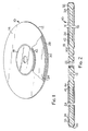
- the SD generally indicated as 10, has annular support 12 with outer and inner raised annular ridges 28 and 42, respectively.
- the annular support is made of a non-magnetic material which is rigid and dimensionally stable.
- the annular support can be made of metal such as aluminum or steel, or of thermosetting or thermoplastic resin. It is typically made of filled polymeric material such as polysulfone, polyphenylene sulfide, polyester, polyetherimide, acrylonitrile-butadiene-styrene, polystyrene, polyamide (nylon) or polycarbonate resins filled with such materials as glass beads, fiber glass and mica (e.g., 20 weight percent fiberglass and 20 weight percent mica and 60 percent polymer resin). Preferably, it is injection molded in a single cavity mold.
- filled polymeric material such as polysulfone, polyphenylene sulfide, polyester, polyetherimide, acrylonitrile-butadiene-styrene, polystyrene, polyamide (nylon) or polycarbonate resins filled with such materials as glass beads, fiber glass and mica (e.g., 20 weight percent fiberglass and 20 weight percent mica and 60 percent polymer resin).
- it is injection molded in
- the base portion of the support may be a flat continuous area joining the first and second raised annular ridges, or spokes which join these ridges.
- the support with spokes may be more difficult to manufacture and possibly less dimensionally stable.
- the recording media films 14 and 16 can be any material which is useful for recording media, can be held in radial tension, and exhibits anisotropy in mechanical properties which affect track stability, such as Young's modulus, thermal expansion, and hygroscopic expansion.
- a recording medium film would comprise a biaxially oriented, semicrystalline substrate on which is coated a pigment/binder recording medium, or other type of magnetizable recording medium such as a thin metal film (e.g., cobalt/chromium).
- layers suitable for optical recording such as described in U.S. Patent 4,365,257 (Gerfast), may comprise the recording layers applied to the substrate film.
- the substrate should have dimensional stability, the feasibility of being stretched, a smooth surface, and the potential for being well adhered to the support material.
- Polyester polyethylene terephthalate, or PET
- polyimide are possible substrate materials for magnetic media. It could be biaxially oriented polyester film or cast film.
- Biaxially oriented polyester is known to have inherent anisotropy because of the stretching it undergoes during its manufacture in the machine direction (direction in which film exits the extruder) and in the transverse direction (90 degrees to the machine direction).
- Measurements made of any such property at regular angular intervals about a point in the center of a section of film can be plotted on polar coordinates to illustrate the correspondence of the property measured and the machine and transverse directions of the film.
- the plot can be roughly elliptical in shape. Because the plot is elliptical, as opposed to circular, there is an anisotropy in the property, which may be quantified as the difference between the minimum and maximum values. Thus one may speak in terms of percentage of anisotropy (e.g., 20 percent anisotropic in a measured property means the maximum value of the property is 20 percent greater than the minimum value of the same property).
- the major and minor axes of the elliptical plot of a given property are known as the major and minor principal orientation axes of that property, and the direction in which they lie in the plane of the film are known as the major and minor principal orientation directions of the film of that property. It has been shown that the major and minor principal orientation directions of the several properties generally agree for a single sample of film, and thus one may use the term "principal orientation axis" or "principal orientation direction" without specifying the specific property measured.
- orientation axes of the films on both sides of a two sided SD improves the stability of the SD, and hence track stability, by allowing the effects of anisotropic films on either side of the disk support to counteract each other as changes occur in the temperature and humidity to which the SD is exposed.
- the alignment of orientation axes also allows non-center cut film to be used in the construction of an SD. This is a benefit as it allows a larger number of SD to be assembled from a portion of film stock, since the entire width may be used.
- subbing layers or lubricant layers may comprise part of the recording medium film.
- the bonding of the magnetic recording sheet to the support of an SD should satisfy the following criteria: high shear strength to withstand the tension of the stretched medium; minimal creep between the recording medium film and the support to maintain data track stability; a smooth bonding surface to provide a smooth recording surface; and a short setting time to allow for high production volume.
- Thermosetting adhesives e.g., cyanoacrylate or epoxy adhesives
- Thermosetting adhesives may be used but have setting or curing times which are difficult to control.
- adheresive means a substance capable of holding two bodies in intimate interfacial contact such that mechanical force can be transferred across the interface
- cure means to polymerize or cross-link into a set, rigid condition.
- the preferred bonding agents are acrylate and methacrylate functional adhesives (e.g. hydantoin hexacrylate) which are curable by radiation, see Komp, J.T. and Mattingly, G.S., Radiation Processing, K&M Publications, Louisville, Kentucky, 1976.
- Some useful classes of such radiation curable materials are: acrylated epoxy resins, acrylated bis-phenol A resins, polyester acrylate resins, acrylated urethane resins, and alkyd acrylates.
- the polyethylene terephthalate commonly used as a substrate for magnetic recording media has a relatively low adhesion to most adhesives which can be cured with an electron beam.
- One method used to overcome this is to prime the back of the polyethylene terephthalate (i.e. the side to be adhered to the support 12) with a priming solution, such as 5 to 20 percent hydantoin hexacrylate plus 0.1 to 0.4 percent Irgacure 651 photoinitiator (made by Ciba Geigy Co.) in methylethylketone or 20 to 100 percent N,N-dimethylacrylamide in methyl ethyl ketone solvent.
- a priming solution such as 5 to 20 percent hydantoin hexacrylate plus 0.1 to 0.4 percent Irgacure 651 photoinitiator (made by Ciba Geigy Co.) in methylethylketone or 20 to 100 percent N,N-dimethylacrylamide in methyl
- Such primers could be coated by rotogravure technique or sprayed onto the back of the polyester film at a thickness of about 0.1 to 0.2 micrometers and cured or partially cured by ultraviolet light.
- the primer solution should be well mixed, and fresh primer should be prepared immediately before use.
- the recording media films 14 and 16 typically have a thickness of about 5 to 200 micrometers. It is the unsupported portion of the recording media films 14 and 16 between the two raised annular ridges which provides a deformable, resilient, annular surface used to record signals from a transducer, such as a magnetic recording head. This surface is known as the data band.
- the outer raised annular ridge 28 terminates in a reference surface 32 which supports recording medium film 14 and determines the spacing between the film and the surface of the base portion 24.
- Reference surface 32 also joins the outside periphery 30 of the support 12 to the outer raised annular ridge 28. Thus, its diameter is greater than that of the innermost part of the outer raised annular ridge.
- the recording medium film 14 is bonded to the reference surface 32.
- an annular attachment surface just beyond the reference surface, and a means for preventing the bonding agent from flowing from the bonding surface to the reference surface 32.
- a groove is employed to prevent a liquid adhesive from flowing from the bonding surface.
- the distance of this spacing is usually about equal to the spacing of the outer reference surface 32 above the surface of the intermediate portion.
- the inside diameter 18 of the recording medium film 14 is adhered to the inner reference surface 44. Thus, its diameter is smaller than that of the outermost part of the inner raised annular ridge.
- Inner reference surface 44 curves into relief groove 60.
- outermost means closest to the outside diameter of the support, and the term “innermost” means closest to the inside diameter of the support.
- the first and second raised annular ridges 28 and 42 could have cross sectional shapes other than those shown in Figure 2.
- the ridges could be triangular in cross section with a rounded apex.
- the apex would provide a reference surface for the recording media films 14 and 16 and a fulcrum around which the films could be drawn.
- the inner and outer reference surfaces 32 and 44 may also be coated with a primer.
- the following primers may be used: a 2 to 5 weight percent solution of hydantoin hexacrylate in methylethylketone with a photoinitiator, pure N,N-dimethylacrylamide, or cyanoacrylate adhesive coated onto the support and dried at room temperature. Both the hydantoin hexacrylate and dimethylacrylamide primers may be exposed to ultraviolet light.
- a small vent hole can be made in the surface of the films 14 and 16 near the inner raised annular ridge in order to equalize inside and outside air pressure.
- the subassembly comprises an inner mounting ring 130, an outer mounting ring 138, and a recording sheet 122.
- the outer diameter of the inner mounting ring 130, the inner diameter of the outer mounting ring 138, and the thickness of the recording medium sheet 122 are chosen to allow the recording medium sheet to fit tightly between the two rings and hold the subassembly together by friction.
- the principal orientation axes are found by noting the axes of the sheet which coincide with the axes of the crossed polarizers at maximum extinction of the transmitted light.
- the major principal orientation axis is then differentiated from the minor axis by measurement of the birefringence (difference in refractive index) of the two axes.
- the subassembly 160 is mounted with the plane of the sheet normal to the propagation direction of incident light 180.
- the light is produced by source 181, and is polarized, in a plane which lies at a 45 degree angle with respect to the vertical, by polarizer 182.
- the plane polarized light is directed through the recording medium sheet 122. If there is an anisotropy in the index of refraction of the sheet, i.e., the plot of refractive index is an ellipse and not a circle, the sheet will change the polarization of the light from plane polarization to elliptical polarization.
- This elliptically polarized light passes through a Babinet compensator 186, equipped with a polarizer 185 having a polarization axis aligned at 90 degrees with respect to that of the polarizer 182. If the recording medium sheet 122 did not elliptically polarize the light, the intensity of light observed through the eyepiece would be zero, as the cross polarizers effectively prevent light transmission. Because the light is elliptically polarized by the recording medium sheet, the light observed at the eyepiece is not extinguished, unless either principal orientation axis of the sheet is aligned with either polarization axis of the polarizers 182 or 185.
- the Babinet compensator is comprised of two wedges of quartz, cut with their optical axes perpendicular to each other, and a means of producing an interference pattern.
- the quartz wedges have equal wedge angles but opposite birefringence. They are assembled in the compensator such that the quartz wedges slide past each other, increasing the total distance of the light path through both wedges. Through the eyepiece, one may observe the interference pattern with no recording medium sheet in the light path.
- the increase in path length required to produce the same interference pattern with the recording medium sheet in the light path as is observed without the sheet in the path, is directly related to the index of refraction of the recording medium sheet.
- the compensator is constructed to accurately measure this increase in path length. This allows one to measure the index of refraction at each principal axis, and the major principal axis is that with the largest index of refraction.
- optical elements such as a monochromatic filter, collumator, or microscope may be included to improve the visibility of the interference pattern.
- determining a principal orientation axis may also be employed. For example, by cutting samples radially from the recording medium sheet along regular angular intervals (typically 15 degrees) from a reference point such as the machine direction. Measurements of Young's modulus of the samples can be made from the stress-strain curves using a tensile testing machine in accordance with the procedures of ASTM Standard D882-83. Maximum and minimum values of Young's modulus as a function of angular position correspond to the major and minor principal orientation axes, respectively.
- Another preferred method to measure the angular dependence of properties of the recording medium sheet is to measure the amount of force needed to achieve a given amount of deformation of the stretched film, for example, grams force per 25 micrometers of downward deformation of the stretched sheet. This measurement is called penetration stiffness.
- Penetration stiffness measurements reflect the mechanical properties of the substrate, and thus can be used to determine the major and minor principal orientation axes of properties such as Young's modulus. Penetration stiffness is measured near the radial center of the data band portion of the stretched film using a probe with a hemispherical tip of approximately 6mm diameter.
- the transducer is a linear variable differential transformer connected to a force measuring instrument.
- Measurements should be made at points equidistant from the center of the SD and angularly separated by the minimum resolution capability of the apparatus used to locate the probe. A deviation of more than plus or minus 0.2 gram per 25 micrometers between the maximum and minimum values would be considered significant.
- Yet another preferred method to measure the angular dependence of properties of the recording medium sheet is to measure the sonic modulus, from which Young's modulus may be calculated.
- a method for measuring sonic modulus is described in ASTM Standard F 89-68 (1973). In general, two piezoelectric transducers, each having a resonant frequency in the range from 3 to 10 kHz, are clamped to a taut sample of film. A sonic pulse is emitted from one transducer, and detected by the other, with appropriate circuitry. Two sets of pulse travel time and transducer separation distance measurements are made, for pulse travel times of at least 50 and 100 microseconds. The longitudinal sonic velocity is calculated, and from it the sonic and Young's moduli may be calculated as described in the standard.
- the central hole 123 should be small enough to have only negligible effect on stress distribution in the portion of the recording medium sheet which will become the data band.
- SD of about 13cm diameter
- a central hole of about 6mm diameter is suitable.
- the lower subassembly 170 shown in Figure 4 is assembled in a similar fashion.
- the major principal orientation axis of the second recording medium film 172 is located, it is also aligned with respect to a reference mark 184′ on the outer mounting ring 138 of lower subassembly 170.
- the axes of the first and second films 122 and 172 will be aligned with each other by assembling the two subassemblies 160 and 170 so that the reference marks 184 and 184′ are aligned with each other.
- the raised annular ridges of support 12 are burnished by moving support 12 circularly over an abrasive lapping film.
- the assembly steps described hereafter are done in a clean room environment in which atmospheric contaminants such as dust and other particulates are removed from the air. Operators should wear a mask and gloves.
- a stretched recording medium sheet about 38 micrometers thick in a subassembly has a penetration stiffness of about six grams force per 25 micrometers of deformation (corresponding to about 48000kPa radial stress).
- the subassemblies are annealed (also known as accelerated stress relaxation) as taught in U.S. Patent 4,623,570 (Alexander, et al.) at column 8, lines 6 to 30. This process reduces penetration stiffness typically to about 2 grams force per 25 micrometers deformation (about 10,000 kPa radial stress) for SD of 13cm diameter.
- the support 12 is cleaned ultrasonically. Then, the adhesive is applied in a thin layer to the inner and outer references surfaces 44 and 32.
- a preferred adhesive is hydantoin hexacrylate, mixed in equal proportions with dimethyl acrylamide. The latter lowers the viscosity of the mixture to ease the application of a very thin, uniform film of the adhesive to the bonding areas at the periphery of the annular support. Care should be taken to avoid the presence of adhesive on the inside diameter portion of the support, the area which would be clamped onto a drive hub. Dried adhesive on that area can adversely affect operation of the SD.
- the side of the stretched recording medium film in each subassembly which will face the support 12 is wiped with heptane and blown clean with ionized air.
- the lower subassembly 170 is placed on lower hub 154; the support 12 is centered on the lower subassembly; upper subassembly 160 is placed over the support and lower subassembly, with the reference marks 184 aligned with each other; and the upper hub 150 is centered on the recording medium sheet 122.
- the upper and lower subassemblies may be clamped together by any convenient means.
- screw 149 is inserted through hub stop 153, the central holes in hubs 150 and 154, and is threaded into the central hole in the actuator 152.
- the outside diameter of hubs 150 and 154 is slightly less than the diameter of the inner raised annular ridge 44, and as the central screw 149 is tightened, the edges of the hubs are drawn into relief groove 60 of Figure 4, consequently forcing the recording media sheets 122 and 172 into close contact with the inner raised annular ridges.
- the adhesive in the completely assembled SD stretching fixture shown in Figure 5 is then cured, e.g. by exposure to an electron beam (e-beam).
- an electron beam e-beam
- One e-beam apparatus useful for this step is an Electro-Curtain machine manufactured by Energy Sciences Inc. in Woburn, Massachusetts.
- the SD stretching fixture is placed on a conveyer belt which in turn travels through the electron beam apparatus.
- the e-beam apparatus is typically operated at 175 kv and a current of 6.7mA when conveying speed is about 12 meters per minute or about 3.3 milliamperes when the conveying speed through the curing chamber is about 6 meters per minute.
- the intensity of each exposure of the SD stretching fixture to an electron beam is no more than about 10 MRad. After the SD stretching fixture has been exposed to the electron beam on one side, it is then exposed in a similar manner on the opposite side.
- hubs 150 and 154 have bevels, 151 and 155 respectively, to ensure that the inner reference surface 44 is actually exposed to the electron beam.
- the outer reference surface 32 is also left accessible to the electron beam, since the upper and lower subassemblies 160 and 170 actually have inside diameters larger than that of the outer reference surface.
- the electron beam can penetrate the polymeric material as well as the magnetic layer of the recording media sheets 122 and 172, but it cannot penetrate the metal of the subassemblies or hub. Thus, it is important that the bond areas not be obstructed by metal.
- the hubs 150 and 154 can be removed by removing the screw 149. Then, the portions of recording media sheets 122 and 172 in the center can be removed by cutting them out, being careful not to cut into the inner reference surface 44.
- the upper and lower subassemblies 160 and 170 are disassembled, and any excess recording media film beyond the outside diameter of the SD support is cut away.
- the stretched film will normally have experienced an increase in penetration stiffness over that which it had after the first annealing step, previously described.
- this added stress is relieved by a second annealing of the assembled SD, similar to that described above, as taught by U.S. Patent 4,623,570 (Alexander, et al.), at column 10, lines 23 to 60.
- Final penetration stiffness is preferably greater than 1.6 g/25 micrometers deformation.
- an SD should be able to maintain track stability with changes in temperature and humidity.
- a procedure for measuring track stability is taught in Alexander, J.L., "Dimensional Track Stability Measurement Using a Standard Head," Computer Technology Review, Summer, 1984, pp. 102-103.
- a magnetic head such as that taught in European Patent Office Publication 0 213 875 (March 3, 1987) is used to record a few concentric pairs of tracks on the medium at different frequencies. For example, one track at 600 KHz is recorded adjacent a 900 KHz track, each such set of tracks being separated by an erased area. The head is moved across each set of tracks in small precise steps as the SD is rotated, and the signal amplitude is measured at each position. The read head is then located between two of the tracks at a point where the signal amplitude from both frequencies is the same.
- the signal amplitude of each frequency is measured at regular intervals around the disk. With low amplitude modulation, these measurements produce a circle when plotted on polar coordinates. Then, environmental conditions are changed, and the same readings are taken. Changes in track shape are detected by changes in the relative strengths of the two read signals. Track anisotropy data are reported as microinches or micrometers of deviation of tracks from their original circular path, as conditions change. The maximum amount of track anisotropy for SD of this invention is generally observed in track pairs recorded near the outer diameter of the SD. For a two-sided disk, the anisotropy value can be calculated as the maximum value of deviation of the individual track pairs, measured on the outer diameter of both sides of the SD.
- one track may be recorded, environmental conditions changed, and the track can be read. Because optical tracks have sufficient resolution for accurate reading (e.g. 1 micrometer bits) and optical disk drives have a servo mechanism driving the read head, the deviation of a track from the original circular path can be detected by observing the movement of the servo mechanism. Alternatively, the previously described two track method can be used.
- Figure 6 shows the geometric relationship of the aligned major principal orientation axes.
- the upper and lower recording medium sheets 122 and 172 lie in mutually parallel planes (not shown) and are concentric about line II′ perpendicular to each sheet.
- the upper sheet has major principal orientation axis JK, which lies in a plane ABCD which is perpendicular to the plane of the upper sheet.
- the lower sheet has major principal orientation axis LM, lying in plane EFGH.
- the dihedral angle ⁇ is formed by planes ABCD and EFGH. Ideally, this angle is zero, in which case the two major axes will lie in a common plane, and as can be shown by a person of ordinary skill in geometry, the axes will necessarily be parallel to each other.
- the anisotropy of the aligned SD of this invention is significantly decreased over non-aligned SD.
- Measured SD distortion over the same change in temperature from 5°C to 60°C decreased to a range of 1.5 micrometers to 2.5 micrometers.
- Two sets of SD were made using the following components: recording medium film of polyester having a pigment/binder type magnetic layer; injection molded polyether imide annular support; and adhesive made of a mixture of hydantoin hexacrylate and N,N-dimethylacrylamide. They were made by processes which were the same in all respects, except that the nine disks of set SD1 were assembled such that ⁇ was 0 degrees, while the eight disks of set SD2 were assembled such that ⁇ was 90 degrees. Each SD was stabilized at 5°C, after which three concentric tracks were recorded at about the middle of the data band. The environment was changed to 60°C and held stable. The SD were then tested for track anisotropy. The average anisotropy of the 9 disks of inventive set SD1 was 2.0 micrometers and that of the 8 disks of set SD2 was 2.8 micrometers.
Landscapes
- Magnetic Record Carriers (AREA)
- Optical Record Carriers And Manufacture Thereof (AREA)
- Manufacturing Of Magnetic Record Carriers (AREA)
Applications Claiming Priority (2)
| Application Number | Priority Date | Filing Date | Title |
|---|---|---|---|
| US205686 | 1988-06-13 | ||
| US07/205,686 US4887178A (en) | 1988-06-13 | 1988-06-13 | Aligned stretched surface recording medium |
Publications (2)
| Publication Number | Publication Date |
|---|---|
| EP0347076A2 true EP0347076A2 (de) | 1989-12-20 |
| EP0347076A3 EP0347076A3 (de) | 1991-08-21 |
Family
ID=22763228
Family Applications (1)
| Application Number | Title | Priority Date | Filing Date |
|---|---|---|---|
| EP19890305593 Ceased EP0347076A3 (de) | 1988-06-13 | 1989-06-02 | Aufzeichnungsträger mit ausgerichteter gespannter Oberfläche |
Country Status (5)
| Country | Link |
|---|---|
| US (1) | US4887178A (de) |
| EP (1) | EP0347076A3 (de) |
| JP (1) | JPH0235629A (de) |
| KR (1) | KR900000850A (de) |
| CA (1) | CA1314981C (de) |
Families Citing this family (5)
| Publication number | Priority date | Publication date | Assignee | Title |
|---|---|---|---|---|
| JPH03178033A (ja) * | 1989-12-06 | 1991-08-02 | Fuji Photo Film Co Ltd | 磁気ディスク |
| JPH0444637A (ja) * | 1990-06-11 | 1992-02-14 | Fuji Photo Film Co Ltd | 磁気ディスク及びその製造方法 |
| US5212615A (en) * | 1991-09-13 | 1993-05-18 | Gomez Ramon S | Data storage device having stretched and distended magnetic media surface |
| US5837380A (en) * | 1995-12-26 | 1998-11-17 | Lucent Technologies, Inc. | Multilayer structures and process for fabricating the same |
| JP2008004252A (ja) * | 2006-05-26 | 2008-01-10 | Tdk Corp | 情報媒体用基板および情報媒体 |
Family Cites Families (19)
| Publication number | Priority date | Publication date | Assignee | Title |
|---|---|---|---|---|
| US3373413A (en) * | 1963-10-30 | 1968-03-12 | Ibm | Pliable magnetic recording disk with direct transducer contact |
| US3509274A (en) * | 1965-09-27 | 1970-04-28 | Sony Corp | Apparatus for the recording of video signals and for the normal slow motion or still picture reproduction of such signals |
| NL6806033A (de) * | 1968-04-27 | 1969-10-29 | ||
| US3537083A (en) * | 1968-11-27 | 1970-10-27 | Univ Illinois | Flexible surface disc for magnetic recorders with central pneumatic orifice |
| EP0047330B1 (de) * | 1980-09-06 | 1984-06-13 | Ibm Deutschland Gmbh | Magnetplatten-Trägerkern aus faserverstärktem Kunststoff |
| US4365257A (en) * | 1981-03-05 | 1982-12-21 | Minnesota Mining And Manufacturing Company | Stretched-film optical recording disc |
| US4625384A (en) * | 1982-04-19 | 1986-12-02 | Minnesota Mining And Manufacturing Company | Method of making a recording disc |
| US4573097A (en) * | 1982-10-13 | 1986-02-25 | Minnesota Mining And Manufacturing Company | Stretched surface recording disk and method of manufacture |
| US4557982A (en) * | 1983-04-07 | 1985-12-10 | Teijin Limited | Magnetic recording flexible disc |
| JPS59195322A (ja) * | 1983-04-20 | 1984-11-06 | Toray Ind Inc | 磁気デイスク |
| US4631609A (en) * | 1984-02-16 | 1986-12-23 | Minnesota Mining And Manufacturing Company | Stretched surface recording disk substrate |
| CA1252206A (en) * | 1984-12-21 | 1989-04-04 | Leslie M. Milner | Stretched surface recording medium |
| JPS61192029A (ja) * | 1985-02-21 | 1986-08-26 | Fuji Photo Film Co Ltd | 磁気デイスクの製造方法 |
| US4623570A (en) * | 1985-03-14 | 1986-11-18 | Minnesota Mining And Manufacturing Company | Stable stretched surface recording medium |
| US4729805A (en) * | 1985-03-14 | 1988-03-08 | Minnesota Mining And Manufacturing Company | Recording medium annealing process |
| JPH075539Y2 (ja) * | 1985-08-03 | 1995-02-08 | 富士写真フイルム株式会社 | 磁気デイスク |
| JPH0644344B2 (ja) * | 1985-08-06 | 1994-06-08 | 富士写真フイルム株式会社 | 磁気デイスク |
| US4800458A (en) * | 1985-09-24 | 1989-01-24 | Fuji Photo Film Co., Ltd. | Recording sheet bonded to a substrate in a magnetic disk |
| JPH0519849Y2 (de) * | 1985-10-18 | 1993-05-25 |
-
1988
- 1988-06-13 US US07/205,686 patent/US4887178A/en not_active Expired - Fee Related
-
1989
- 1989-05-29 CA CA000601039A patent/CA1314981C/en not_active Expired - Fee Related
- 1989-06-02 EP EP19890305593 patent/EP0347076A3/de not_active Ceased
- 1989-06-09 JP JP1148227A patent/JPH0235629A/ja active Pending
- 1989-06-12 KR KR1019890008050A patent/KR900000850A/ko not_active Withdrawn
Also Published As
| Publication number | Publication date |
|---|---|
| CA1314981C (en) | 1993-03-23 |
| US4887178A (en) | 1989-12-12 |
| KR900000850A (ko) | 1990-01-31 |
| EP0347076A3 (de) | 1991-08-21 |
| JPH0235629A (ja) | 1990-02-06 |
Similar Documents
| Publication | Publication Date | Title |
|---|---|---|
| EP0194890B1 (de) | Stabiles Aufzeichnungsmedium mit gespannter Oberfläche | |
| KR20080108391A (ko) | 광학 기록매체 | |
| US4729805A (en) | Recording medium annealing process | |
| US4887178A (en) | Aligned stretched surface recording medium | |
| JP2001043566A (ja) | 光情報媒体およびその製造方法 | |
| US4963209A (en) | Method for making stretched surface recording disk | |
| US6743315B2 (en) | Bonding apparatus and bonding method of optical disks | |
| USRE33187E (en) | Stable stretched surface recording medium | |
| CA1252206A (en) | Stretched surface recording medium | |
| US4836890A (en) | Method for producing optical information recording disk | |
| EP0305199A2 (de) | Zentriernabe für eine Aufzeichnungsplatte | |
| JPWO2003004270A1 (ja) | 巻回積層体 | |
| US5745443A (en) | Magneto-optical disc having a protective film with minimal projections and method of production of same | |
| US4835647A (en) | Stretched surface recording medium | |
| JPS58189838A (ja) | 記録デイスク | |
| EP0612069A2 (de) | Magnetooptische Platte | |
| JP2765858B2 (ja) | 磁界変調型デイスク | |
| JPS6080125A (ja) | 積層フィルム | |
| JPH03296930A (ja) | 光ディスクの製造方法 | |
| JP2730780B2 (ja) | 光学式情報記録円板およびその製造方法 | |
| JPS6326854A (ja) | 光学式デ−タ記憶デイスクの製造に関する改良 | |
| JPS63255884A (ja) | 光デイスク用中心金具 | |
| JP2510214B2 (ja) | 光ディスクへのハブの取付方法 | |
| JPH10124934A (ja) | 光記録媒体の製造方法 | |
| JPH11339381A (ja) | 光記録媒体の装着方法 |
Legal Events
| Date | Code | Title | Description |
|---|---|---|---|
| PUAI | Public reference made under article 153(3) epc to a published international application that has entered the european phase |
Free format text: ORIGINAL CODE: 0009012 |
|
| AK | Designated contracting states |
Kind code of ref document: A2 Designated state(s): DE FR GB IT |
|
| 17P | Request for examination filed |
Effective date: 19910102 |
|
| PUAL | Search report despatched |
Free format text: ORIGINAL CODE: 0009013 |
|
| AK | Designated contracting states |
Kind code of ref document: A3 Designated state(s): DE FR GB IT |
|
| 17Q | First examination report despatched |
Effective date: 19920923 |
|
| STAA | Information on the status of an ep patent application or granted ep patent |
Free format text: STATUS: THE APPLICATION HAS BEEN REFUSED |
|
| 18R | Application refused |
Effective date: 19931115 |