EP0346984A2 - Mécanisme d'entraînement pour un appareil à cassette à bande magnétique avec un moteur d'entraînement de cabestan et avec une tige asservie, entraînée par un moteur en va et vient - Google Patents
Mécanisme d'entraînement pour un appareil à cassette à bande magnétique avec un moteur d'entraînement de cabestan et avec une tige asservie, entraînée par un moteur en va et vient Download PDFInfo
- Publication number
- EP0346984A2 EP0346984A2 EP89201503A EP89201503A EP0346984A2 EP 0346984 A2 EP0346984 A2 EP 0346984A2 EP 89201503 A EP89201503 A EP 89201503A EP 89201503 A EP89201503 A EP 89201503A EP 0346984 A2 EP0346984 A2 EP 0346984A2
- Authority
- EP
- European Patent Office
- Prior art keywords
- switching
- servo
- drive
- microprocessor
- motor
- Prior art date
- Legal status (The legal status is an assumption and is not a legal conclusion. Google has not performed a legal analysis and makes no representation as to the accuracy of the status listed.)
- Granted
Links
Images


Classifications
-
- G—PHYSICS
- G11—INFORMATION STORAGE
- G11B—INFORMATION STORAGE BASED ON RELATIVE MOVEMENT BETWEEN RECORD CARRIER AND TRANSDUCER
- G11B15/00—Driving, starting or stopping record carriers of filamentary or web form; Driving both such record carriers and heads; Guiding such record carriers or containers therefor; Control thereof; Control of operating function
- G11B15/02—Control of operating function, e.g. switching from recording to reproducing
- G11B15/026—Control of operating function, e.g. switching from recording to reproducing by using processor, e.g. microcomputer
-
- G—PHYSICS
- G11—INFORMATION STORAGE
- G11B—INFORMATION STORAGE BASED ON RELATIVE MOVEMENT BETWEEN RECORD CARRIER AND TRANSDUCER
- G11B15/00—Driving, starting or stopping record carriers of filamentary or web form; Driving both such record carriers and heads; Guiding such record carriers or containers therefor; Control thereof; Control of operating function
- G11B15/02—Control of operating function, e.g. switching from recording to reproducing
- G11B15/10—Manually-operated control; Solenoid-operated control
- G11B15/103—Manually-operated control; Solenoid-operated control electrically operated
Definitions
- the invention relates to a drive for a magnetic tape cassette device with a Tonwellenantriebsmotor and with a servomotor driven by a servo gear, back and forth longitudinally displaceable servo rod, which controls functional parts of the device, such as a head plate, a loading mechanism and a switching mechanism with the aid of its displacement path of a switching signal receiving microprocessor and a control device for the servo motor.
- DE 33 15 822.3 C2 also discloses a magnetic tape device in which a servo rod can be driven back and forth in the longitudinal direction of the rod by means of a motor in order to carry out loading or switching functions between the running directions. To perform these functions, the servo rod must always be moved to a reference end position, from which the various functions can then be derived. This is both mechanically and electrically complex and requires a great deal of time between the decommissioning of a game function and the restarting in another function.
- the object of the invention is to provide a servo and control mechanism for a magnetic tape cassette device which simplifies the construction of the device and in which the control and regulation functions are taken over by as few as possible partly electrical and partly mechanical components.
- control rod mechanically or electrically via the switching means that works on the microprocessor.
- the control rod and the switching element mechanically take over the adjustment of the head plate and the changeover of the winding plate and servo drive. It is also important that the control rod in turn also determines when the switching element can perform independent movements.
- the microprocessor is programmed so that it not only Switching signals of the switching means are electrically converted into control commands; it is also set up in such a way that it knows at any time or takes a self-orientation by moving to the next switching point provided for switching functions, in order to ensure that the servo function stage the drive is currently in. For this purpose, he uses the statement of the last, previously received switching signal stored in him and the new switching signal, which makes a statement about the current position of the switching means. In this way, if, for example, the power has been switched off, the microprocessor can find an adjacent switching point via the control rod in any phase of the servo operation and can then issue the necessary control commands for the servo motor, the sound wave drive motor and the holding magnet device.
- the switching means is a switch which emits a switching signal when opening and closing by means of a switching lug.
- a switch is simple and reliable; the opening and closing can be recognized by the microprocessor.
- the microprocessor specifies the direction of rotation of the servo motor via the control device and the Power supply of the servo motor switches between a high supply voltage for the operation of the charging and servomechanism as well as fast winding and a low supply voltage for the winding plate drive during play.
- the high supply voltage of the servo motor ensures that the servo movements can be carried out quickly and the rewinding of a cassette can be completed in a relatively short time.
- the low supply voltage enables the drive of one or the other winding plate with the same servo motor.
- control device is provided with bridge power amplifiers provided in the motor feed lines.
- bridge power amplifiers offer a convenient servo motor.
- the control device is provided with a pulse detector which detects operational functions of the servo motor via the voltage supply of the bridge power amplifiers. The detection takes place in such a way that the voltage supply lines of the bridge power amplifiers are connected to a differentiator which forms countable pulses from the pulsating DC voltage of the motor.
- a servo commutator motor operated with direct current interrupts the current flowing through it at the time of commutation. These commutation interruptions are used to form countable pulses.
- the pulses of the differential element are fed via a monoflop to the microprocessor, which counts the pulses and forms time values from them.
- Such time values can be used for speed monitoring of the motor, the belt length counting or the belt stop detection.
- the microprocessor determines the actual times between successively received switching signals and compares them with a stored target times and that the microprocessor switches the servo motor to the direction of ejection in the event of impermissible time differences.
- the microprocessor can thus take over monitoring functions, for example by determining whether the control rod exceeds a certain desired time from the start of its movement from a switching point of the switching means to the reaching of the next switching point. Target time overruns can indicate errors. If the target time is exceeded, the microprocessor switches the servo motor in the eject direction.
- the mechanical switching element is released at the end of the servo mode for initiating the play mode from the control rod to carry out its own movements, with the switching element being electrically switched on by the switching means as a result of the switching element's own movement Tonwelle-drive motor and the lowering of the supply voltage of the servo motor and mechanically switching the servo motor gear from the servo drive (control rod) on the belt drive (winding plate) is effected.
- Tonwelle-drive motor Tonwelle-drive motor
- the Servomechanism At the end of a servo movement of the Servomechanism have several mechanical and electrical switching functions to start the game operation.
- the servo motor must be prepared for play, the sound wave drive motor must be started and the amplifier must be muted if it does not have to be switched on.
- the servomotor gear must be changed from the servo drive to the winding drive. This can be done in the device structure alone via the switching element.
- the servo motor transmission is designed as a two-function transmission with adapted reduction gear trains for the control rod drive and the winding plate drive and that the efficiency of the reduction gear train for the winding plate drive is designed such that the speed-torque curve of the servo motor acting on the winding plate is such adapts widely to the winding speed-winding torque curve so that the tape tensile force on the winding reel over the winding speed or the changing winding diameter is largely the same, the parameters n / M mo of the servo motor, the transmission ratio and the efficiency with the gear material pairing being used as parameters for the adaptation will.
- Such an optimization makes it possible to save a slip clutch between the drive and the winding plate.
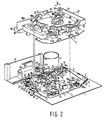
- FIG. 1 and 2 show a chassis plate 1, acting as a frame, of a magnetic tape cassette device with a head plate 3, which can be pivoted about an eccentric pivot point 5.
- the head plate 3 is U-shaped and has first and second legs 9 and 11 projecting from the ends of its base 7 in the same direction. The legs 9 and 11 engage in corner areas 12 and 13. While the first leg 9 interacts with a servo rod 14 (not shown in FIG. 1), the second leg 11 forms a functional part which cooperates with an electrical holding magnet device 15.
- the base 7 of the head plate 3 carries a magnetic head 16 and pressure rollers 17a, 17b which can be pivoted relative to the base 7.
- the pressure rollers 17a and 17b can be brought together with sound waves 18a and 18b in order to guide the magnetic tape past the magnetic head 16 in one direction or the other.
- the pivoting of the head plate 3 takes place in each case via the servo rod 14.
- This servo rod 14 acts on a spring-loaded transport lug 19 which is pivotably arranged on the leg 9.
- the head plate 3 can pivot about the eccentric pivot point 5 via the servo rod 14, and in the process rotate clockwise each time it is pushed by means of the servo rod 14.
- the electro-holding magnet device 15 consists of a magnet coil 20, into the coil cavity 21 (FIG. 3) of which legs of U-shaped, magnetically separated armature irons 22, 23 are inserted.
- the two anchor irons 22, 23 lie one above the other, the respective anchor iron legs 22a, 23a overlapping in pairs.
- the Iron yokes 22b, 23b lie on opposite coil ends 20a, 20b.
- the electric holding magnet device 15 is fixedly mounted on the chassis plate 1.
- Pole shoes 23c and 22c are formed on the free leg ends and cooperate with a first anchor plate 24 and a second anchor plate 25.
- the first anchor plate 24 is rotatably arranged on a carriage 26 by means of a pin 24a.
- This slide 26 engages with the pin 24a in a guide groove 27 of the leg 11.
- a guide pin 26b of the slide 26 can be guided along in a curved groove 28 of the functional part 11.
- the arcuate groove 28 runs at an oblique angle in the shape of an arc in the direction of the electro-holding magnet device 15.
- a spring 29 ensures that the guide pin 26b normally moves into the end region 28a of the arcuate groove 28. In this position, the slide 26 runs above the leg 11 parallel to the latter.
- the second anchor plate 25 is rotatably arranged on an arm 30 by means of a pin 25a.
- the arm 30 itself is L-shaped and has a shorter arm part 30a, which also carries the second anchor plate 25 and which is rotatable at its end 30b about an axis of rotation 31 in the direction of a double arrow 32.
- a longer arm part 30c extends parallel to that Magnetic coil 20 up to a side surface 33 of the carriage 26, where it ends in the vicinity of a nose 34 of the carriage with an oblique run-up surface 35.
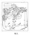
- Fig. 5 shows the so-called stand-by or rest position.
- the magnet coil 20 is de-energized and the armature plate 24 has moved away from the pole shoes 23c of the armature iron 23.
- the anchor plate 25 bears against the pole shoes 22c, since a spring 36 ensures constant contact.
- the spring 37 holds the head plate 3 pivoted counterclockwise in the rest or stand-by position. Both the magnetic head 16 and the pressure rollers 17a and 17b completely release a magnetic tape, not shown, which runs between the pressure rollers / pairs of sound waves 17a, 18a / 17b, 18b in front of the magnetic head 16. If the head plate is now to be pivoted into the playing position, ie a first working position (FIG.
- the servo rod 14 abuts the transport lug 19 in the dotted position, as a result of which the head plate 3 is pivoted clockwise.
- the magnetic coil 20 initially remains unexcited. With the Swiveling the head plate 3 clockwise also moves the leg 11 in the direction of the electro-holding magnet device 15.
- the nose 34 of the carriage 26 abuts against the inclined surface 35 of the longer arm part 30c.
- the spring 36 is dimensioned so weak that the nose 34 pushes the surface 35 and thus the longer arm part 30c counterclockwise outwards.
- the guide pin 26b remains in the end region 28a.
- the functional part 11 guides the first anchor plate 24 against the pole shoes 23c.
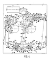
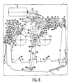
- the solenoid 20 is now energized and the armature plate 24 is held on the pole pieces 23c (FIG. 4). Thus, the head plate 3 is also held in the game position, the first working position. If the game operation is over or should be switched to fast forward or reverse, then the solenoid 20 is de-energized, and the spring 37 pivots the head plate counterclockwise back to the rest or standby position. How to approach the game position has already been described. Reaching and holding the head plate in the fast winding position (FIG. 6), ie the second working position, will now be explained. In order to get into the fast winding position (FIG. 6), the magnet coil 20 is first excited.
- the second armature plate 25 is already in contact with the pole shoes 22c, and the magnetic holding force is now added to the force of the spring 36. It has become more difficult to pivot the longer arm part 30c counterclockwise.
- the servo rod 14 runs once and swivels the head plate 3 clockwise.
- the nose 34 of the carriage 26 is now unable to pivot the longer arm part 30c away. This means that the nose 34 must avoid the surface 35 of the longer arm part 30c.
- the guide pin 26b is pushed to the other end 28b of the arcuate groove 28.
- the carriage 26 simultaneously slides in the direction of an arrow 26c with the guide pin 24a in the groove 27 in the direction of the electro-holding magnet device 15.
- the solenoid 20 is de-energized. This leads to the armature plate 24 becoming detached from the pole shoes 23c, and the spring 37 can turn the head plate 3 counterclockwise back into the rest or standby position (FIG. 5). Because of the construction just described, it must always be returned to the rest or standby position before it can be moved back to the play or fast rewind position.
- the motor 40 serves to control the movements of the head plate 3 and to drive the winding plates 42, 43.
- the sound wave motor 41 drives the sound waves 18a, 18b via a peese 44. This drive takes place via flywheels 45a, 45b.
- the peese 44 is placed in an S-shape around the oscillating disks 45a, 45b in order to bring about opposite directions of rotation of the sound waves 18a, 18b.
- the motors are controlled by a microprocessor 46 which is arranged on a circuit board 47.
- the circuit board 47 is arranged on the chassis board 1.
- the servomotor 40 acts on a servo gear 48a, which includes a worm shaft 48 and a reduction gear 49, which consists of two sub-gears 49a and 49b, and a central gear 50.
- a pivot arm 51 is pivotable about the axis 50a of the central gear 50, on which a transmission gear 52 is rotatably mounted.
- the transmission gear 52 can be pivoted via a friction clutch (not shown) between the swivel arm 51 and the central gear 50 in such a way that the transmission gear 52 can either drive one winding plate 42 or the other winding plate 43.
- the servo rod 14 can be driven in a longitudinally displaceable manner by means of a switching wheel 53.
- the switching wheel 53 belongs to a switching element 54 and is rotatably mounted on an actuating element 55 of the switching element 54.
- the switching element 54 also has a release element 56 and a positioning element 57.
- the switching element 54 is rotatably mounted about an axis 58 and is loaded clockwise by means of a resilient arm 59.
- a control switch 60 is arranged on the chassis plate 1, the switching lug 61 of which can cooperate with the positioning member 57 of the switching element 54 and a switching extension 62 of the servo rod 14.
- the switching lug 61 takes no load a middle position from which it can be pivoted away on two sides. In the middle position, the switch 60 is open, with the switching lug 61 pivoted away to the side, the switch 60 is closed. With each new movement of the switching lug 61, the switch 60 emits a signal.
- the positioning member 57 has a guide pin 63, the position of which relative to the servo rod 14 is determined by the latter.
- a first determining position is shown in FIGS. 3, 4 and 6, while the second determining position is shown in FIG. 5.
- the servo rod has an edge 64 for positioning in the second position.
- the first position is determined by a groove 65 in the servo rod 14.
- the control rod thus determines the position of the switching element 54 between the start of the servo operation and the end of the servo operation, either directly via the groove 65 or indirectly via the control member 73, where the drive in Play mode or fast reel mode passes.
- the three-armed switching element 54 has a wide fork 66 on its release member 56, which cooperates with a limiting pin 67 on the swivel arm 51.
- Two grooves 68, 69 are provided on the chassis plate 1.
- the groove 68 is L-shaped, while the groove 69 is designed as an elongated hole in the direction of displacement of the servo rod 14.
- the direction of displacement of the servo rod is indicated by a double arrow 70.
- the groove 68 has a groove arm 68a in the direction of the double arrow 70 and an arm 68b running perpendicular thereto in a direction perpendicular to the double arrow 70. These are vertical Direction is indicated by an arrow 71.
- Guide pins 72a, 72b of a control member 73 engage in the grooves 68 and 69.
- This control member 73 is forced by means of a spring 74 in two directions, once in the direction of a control lug 75 which is firmly connected to the free end of the first leg 19.
- the control lug 75 is located in the vicinity of the transport lug 9 the second direction in which the spring 74 urges the control member 73 is the direction indicated by the arrow 71.
- a slope 76 is provided on the control member 73, which can cooperate with a slope 55a on the actuator 55.
- the control member 73 is L-shaped with a short arm extension 77 which carries a travel pin 78. This driving pin interacts with a set up 79 in the servo rod 14. This furnishing backdrop consists of two tracks 79a, 79b, which are connected via a Schadow latch 80.
- This Schadow pawl 80 is designed to be resilient in such a way that the traction pin can travel through it in the direction indicated by an arrow 81, but not in the opposite direction. After the travel pin 78 has entered the web 79b through the Schadow pawl 80, it can no longer return to the Schadow pawl, but must run in the web 79b, which runs in the direction of the double arrow 70.
- the servo rod 14 is provided with a coupling member 82, which establishes the connection to an elevator slide 83.
- This elevator slide 83 has an extension 84, which can press against the coupling member 82 on one side, in the direction of an arrow 85.
- the direction of the arrow 85 agrees with the direction of insertion of a cassette 86 into a loading mechanism 87 which the lift slide 83 belongs to.
- the loading mechanism 87 has a lift shaft 88 which receives the cassette 86.
- the lift slide 83 is guided in a sliding guide 89 so as to be longitudinally displaceable in the direction of the double arrow 70.
- the slide guide 89 is part of a plastic part 90, which is connected to the chassis plate 1 in a manner not shown.
- the lifter slide 83 is somewhat U-shaped with a long leg 91, a base 92 and a short leg 93.
- two oblique scenes 94 are provided, in which pins 95 of the elevator shaft 88 are led.
- the short leg 93 is also provided with an oblique backdrop 96 which interacts with a tab 97 of the elevator shaft.
- an over-center spring 98 is provided, which is supported on the one hand on the plastic part 90 and on the other hand on the long leg 91 of the elevator slide 83.
- the plastic part 90 has a horizontal edge 90a, which is delimited by a vertical edge surface 90b.
- a further vertical edge surface 90c extends parallel to the vertical edge surface 90b.
- the distance between the two vertical edges 90b and 90c corresponds to the distance between the pins 95, the pins 95 being able to move along the vertical edge surfaces 90b and 90c.
- Fig. 1 also shows that the swivel arm 51 is arranged between the winding plates, which is the transmission gear 52 stores.
- the swivel arm 51 has a joint 99 which is engaged by an adjusting lever 100 which can pivot about a tilting bearing 101.
- a fixed tooth segment 102 is arranged, on which the transmission gear 52 can roll.
- the transmission gearwheel has a partial gearwheel 52a on its underside.
- the actuating lever 100 remote from the joint 99 the actuating lever 100 carries a pin 103 which is displaceable to a limited extent in an elongated hole 104.
- the elongated hole 104 is located in a slide 105, which has pins 106 which are displaceable in elongated holes 107 of the chassis plate, specifically parallel to the double arrow 70.
- Eccentric discs 109 which are connected to toothed segments 110, can be pivoted on the chassis plate 1 about axes 108. These toothed segments 110 work together with toothed racks 111 of the slide 105.
- the pin 103 can move the slide 105 in one or the other direction of the double arrow 70 after reaching one or the other end edge of the elongated hole 104 .
- the eccentric discs 109 are rotated.
- the pressure rollers 17a, 17b are mounted in brackets 112a, 112b, which in turn can be pivoted about axes 113.
- the axes 113 are arranged on the head plate 3.
- the brackets 112a and 112b have pins 114 which can run over the surfaces of the eccentric discs 109.
- the brackets 112a and 112b are spring-loaded with the aid of springs 115a, 115b in the direction of the sound waves 18a, 18b.
- the springs 115a and 115b also always press the pins 114 against the eccentric discs 109.
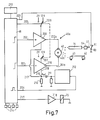
- Figure 7 shows a circuit device used to control all drive functions.
- a motor controller 46a is assigned to the microprocessor 46.
- the servo motor 40 of the drive is operated via a bridge power amplifier, consisting of two power amplifiers 208 and 209, which are controlled by the microprocessor 46 via lines 201 and 202 and which are switched through to the servo motor 40 via lines 201a and 202a.
- the motor controller 46a provides a switchover of the voltage supply of the power amplifiers 208 and 209 between 2 V and 12 V.
- the switchover is carried out with the aid of switches 206 and 207, the switchover of which takes place via a control line 203 of the microprocessor.
- the servo motor 40 is selectively switchable to the servo rod 14 or one of the winding plates 42, 43 via a clutch 40a, which is indicated by a dashed line and consists of the gear 53 and the switching element 54 Initiate switching lug 61 of switch 60. Each time the switch 60 is triggered, pulses are generated which are supplied to the microprocessor 46 via the control line 205.
- the current flowing through the servo motor 40 and the power amplifiers 208 and 209 is supplied to a grounded resistor 210 via lines 217 and 218. Since the current flowing from the servomotor 40 via the lines 201a and 218 is pulsating due to commutation interruptions, a pulsating voltage drop results at the switching point 219. These needle-like pulses become via a differentiating element 211 and a monoflop 212 Reckeck pulses processed and supplied to the microprocessor 46. This microprocessor 46 counts the pulses and adds them. The added impulses can be displayed on a display 213 in the form of a tape length display and direction of rotation display.
- Keys 214 are provided with which individual functions of the drive can be determined manually. These include, for example, reversing the tape direction, fast forwarding and rewinding, and cassette ejection.
- the keys 214 are all connected to the microprocessor 46, which then controls the function desired by pressing the key.
- the microprocessor controls a power amplifier 216, which controls the electro-holding magnet 15 in such a way that the head plate 3 can be held in the play position or in a fast winding position.
- the switch 60 is an on / off switch, the activation and deactivation of which are recognized by the microprocessor 46 as defined switching signals.
- the microprocessor recognizes that the switching lug 61 becomes free when switched on and moves automatically into its central position and that the switching lug 61 is pushed away from the central position when switched off.
- the position switched on and switched off provides information about the switching point at which control rod 14 and switching element 54 are currently located within the movement sequence of the servomechanism.
- the microprocessor counts the square-wave pulses emitted by the monoflop 212 during servo operation and uses them to form an actual-time inter between the individual switching points vall in which the servomechanism has moved from one switching point to the other switching point.
- the time intervals that the Servomechanis now needs to get from one switching point to the other are stored in the microprocessor.
- the microprocessor constantly checks whether these time intervals are also observed. If the target intervals are not maintained within a certain tolerance, the microprocessor automatically switches the servomotor 40 to the direction of ejection rotation.
- the microprocessor is also designed in such a way that it recognizes at which function point the servomechanism was located in the last switching signal received previously.
- a switching pulse formed when opening is evaluated by the microprocessor 46. This recognizes that the switch 60 is open; it sets the motor control inputs 201, 202 and 203 so that the servo motor 40 can start up with a voltage of 12 V in the desired servo feed rotation direction.
- the power amplifiers 208 and 209 apply the full 12 V supply voltage to the servo motor 40.
- the mechanically coupled servo motor 40 now moves the servo rod 14 further in the pull-in direction 85.
- the attachment 84 now no longer needs to take the coupling member 82 along and the lift slide travels alone by means of the force of the dead center spring in the insertion direction 45, and so far until the pins 95 can slide down along the vertical edge surfaces 90b and 90c, the pins 95 also sliding downwards in the oblique scenes 94.
- the flap 97 slides down on the backdrop 96. This downward sliding is ended when the lift slide 83 has reached its rear end position according to FIG. 2. In this position, the elevator shaft 88 has reached its rear and lower positions, and the cassette 86 is placed on winding mandrels 116, 117.
- the servo motor gear 48a has switched off the winding plate drive simultaneously with the engagement of the servo (control rod) drive.
- the servo motor gearbox is therefore a two-function gearbox which works on the control rod 14 in the servo mode and on one of the winding plates 42, 43 in the fast winding or play mode.
- the drive of the servo rod 14 via the switching wheel 53 is self-retracting in the direction of extension counter to the arrow 85.
- the drive with the switching wheel 53 is self-releasing. This means that the ratchet wheel by itself when the servo rod 14 moves in, when the control member 73 does not specify a travel limit can come out of engagement with the central gear.
- the self-retracting direction of the switching wheel 53 ensures that the guide pin 63 remains on the corner 125 without being guided in a particular manner.
- the control rod 14 moves to the right in the play position according to FIG. 4, as far to the right as is indicated in FIG. 4 by dashed lines.
- the servo rod 14 has pivoted the head plate 3 into its play position in the manner already described, as can be seen from FIGS. 1 and 4.
- the switching shoulder 62 of the servo rod 14 abuts the switch nose 61 and closes the switch 60.
- the closing triggers a switching pulse which is supplied to the microprocessor 46 via the line 205 becomes.
- the microprocessor recognizes the first reversing switching point and controls the inputs 201 and 202 so that the power amplifiers 208 and 209 stop the motor 40 after a safety overflow time of approximately 150 msec and start in the opposite direction of rotation.
- an overload clutch not shown, is inserted between the gear wheels 49a and 49b.
- the microprocessor simultaneously switches on the holding magnet device 15. The head plate is thus held in the game position.
- the microprocessor has monitored the actual time interval between the start switching point and the first reversing switching point with the target time interval known to it. If the actual-time interval had exceeded the target-time interval, the microprocessor would have automatically reset the servo motor 40, ie reversed in the discharge direction.
- the microprocessor 46 starts the servomotor 40 in the opposite direction.
- the servo rod 14 starts again in the opposite direction.
- the switch 60 opens; it emits a switching pulse that the microprocessor recognizes as a second reversing switching point.
- the microprocessor notes that the servo drive from the second reversing switching point is on the way to the servo end switching point, in which it is switched to fast winding or play mode. Shortly before reaching the servo limit switch point, the control member 73 and the switching element 54 have separated from one another. Due to the force of the spring 59, the switching element 54 pivots clockwise, the limiting pin 67 being released by the wide fork 66.
- the swivel lever 51 can place the transmission gear 52 against one of the winding plates 42, 43.
- the servomotor gear 48a is thus switched over to the winding plate drive when the switching element 54 is pivoted from the servo operation (the switching element 54 has guided the switching wheel 52 away from the central wheel 50; this position is indicated in FIG. 7 with the mechanical coupling 40a shown in broken lines).
- the pressure roller 17a / 17b was applied in the pulling direction to the associated shaft 18a / 18b via the pivot lever 51 and the adjusting lever 100.
- the positioning member 57 abuts the switch nose 61 and the switch 60 is closed.
- the switch outputs a switching pulse to the microprocessor 46 via the line 205.
- the microprocessor 46 has again compared the actual time interval with the desired time interval and has determined a correct desired time interval. The servo process can therefore continue.
- the microprocessor 46 switches to tighten the belt, the servo motor for e.g. B. 25 msec to 12 V without current limitation. Then switch to 12V with current limitation for 250 msec. In this time interval, the microprocessor switches on the sound wave motor 41.
- the game process starts with high torque. After the 250 msec has elapsed, the microprocessor switches the servo motor 40 from 12 V to 2 V via line 203 and switches 206 and 207.
- the servo motor 40 continues to rotate at a lower torque.
- the servomechanism is now switched off and the drive plays a cassette.
- the adjusting lever 100 For pressure roller adjustment, the adjusting lever 100 has moved the slide 105 in the direction of an arrow 120 to the left.
- the toothed racks 111 have rotated the eccentric discs 109 clockwise via the toothed segments 110.
- the pin 114 of the bracket 112a on the right has left the surface 121 of the eccentric 109 and has run against an edge 122, the spring 115a constantly pressing the pin 114 against the edge 122.
- the pressure roller 17a has thus been placed against the shaft 18a.
- the running of the pin 114 from the surface 121 over a corner 123 to the edge 122 has at the same time the result that the displacement of the slide 105 previously initiated by the actuating lever 100 in the direction of the arrow 120 has now been taken over by the pin 114.
- the electrical control of the drive always takes place via a switch 60 and the microprocessor 46. Control commands from the outside go to the microprocessor 46 via keys 214 or the like.
- the end of the tape ie the stopping of the motor 40, is also detected by the microprocessor 46.
- the current flowing through the servo motor 40 also flows through a resistor 210 (FIG. 7).
- the current pulsating through resistor 210 causes a pulsating voltage drop across resistor 210.
- the voltage pulses are differentiated at a differentiator 211.
- a monoflop 212 is triggered with the differentiated voltage.
- the trigger pulses are fed via line 204 to the microprocessor 46, which counts the pulses.
- the microprocessor 46 detects the tape standstill and reverses the direction of motor rotation by reversing the power amplifiers 208, 209 via the lines 201 and 202.
- This reversal of the direction of rotation causes the adjusting lever 100 to initially adjust the slide 105 in the direction of an arrow 124 until the pin 114 on the left eccentric disk 109 over the corner 123 has run and the pin 114 has then taken over the further displacement of the slide 105 in the direction of the arrow 124 via the edge 122.
- the pressure roller 17a has become detached from the tone shaft 18a, while the pressure roller 17b has placed itself against the tone shaft 18b.
- the transmission gear 52 is swung over from the winding plate 42 to the winding plate 43.
- the switches 206 and 207 are briefly switched to 12 V by the microprocessor in order to accelerate the switching process.
- the drive can be switched off at any time during servo operation; it then remains in the off position when the top plate has fallen off.
- the servomotor 40 is first switched on in the ejection direction for a reset.
- the control rod 14 moves to the left to the next switching point and recognizes it. From this point of view, the servo processes run in the manner already described.
- the pulses emitted by the monoflop 212 via the line 204 to the microprocessor 46 are counted, added up and shown on the display.
- the pulse count includes tape length and direction of rotation display.
- the servo motor 40 drives a servo motor gear 48a, which is designed as a two-function gear with adapted reduction gear trains for the control rod drive and the winding plate drive.
- the efficiency of the reduction gear for the winding plate drive is optimized so that the speed-torque curve of the servo motor 40, which is effective on the winding plate, adapts so far to the winding torque-winding diameter curve on the winding plate that the veröaif that the winding plate can be driven without interposing a slip clutch.
- the gear between the servo motor 40 and the winding plate 42 or 43 consists of the worm shaft 48, the reduction gear 49, which consists of the two partial gears 49a and 49b connected via an overload clutch, the central gear 50 and the transmission gear 52. These are therefore all gears between the shaft of the servo motor 40 and the winding plates 42 or 43.
- the winding torque on the winding reel changes when the winding diameter changes or the winding speed changes.
- the winding torque is high and the speed of the winding winding plate is high.
- the torque of a DC servo motor is high at low speed and low at high speed.
- the solid characteristic curve n / M mo shows that the engine speed n m decreases approximately linearly with increasing engine torque.
- the winding torque M wi required on the winding plate is also increasing, the characteristic curve n wi / M wi being curved.
- the position of the characteristic curves can be approximated to one another in a central area by adjusting the gearbox efficiency, so that, in the end, an approximately constant tensile force F B , measured in cN, measured across the diameter of the tension winder on the winding winder. is obtained. This means that a slip clutch that compensates for the torque differences can be dispensed with.
Landscapes
- Engineering & Computer Science (AREA)
- Computer Hardware Design (AREA)
- Toys (AREA)
- Control Of Position Or Direction (AREA)
- Adjustment Of The Magnetic Head Position Track Following On Tapes (AREA)
- Automatic Tape Cassette Changers (AREA)
Applications Claiming Priority (4)
| Application Number | Priority Date | Filing Date | Title |
|---|---|---|---|
| DE3820501 | 1988-06-16 | ||
| DE3820501 | 1988-06-16 | ||
| DE3915201A DE3915201A1 (de) | 1988-06-16 | 1989-05-10 | Laufwerk fuer ein magnetbandkassettengeraet mit tonwellen-antriebsmotor und mit einer von einem motor angetriebenen, hin und zurueck laengsverschieblichen servostange |
| DE3915201 | 1989-05-10 |
Publications (3)
| Publication Number | Publication Date |
|---|---|
| EP0346984A2 true EP0346984A2 (fr) | 1989-12-20 |
| EP0346984A3 EP0346984A3 (en) | 1990-09-26 |
| EP0346984B1 EP0346984B1 (fr) | 1994-10-05 |
Family
ID=25869183
Family Applications (1)
| Application Number | Title | Priority Date | Filing Date |
|---|---|---|---|
| EP89201503A Expired - Lifetime EP0346984B1 (fr) | 1988-06-16 | 1989-06-12 | Mécanisme d'entraînement pour un appareil à cassette à bande magnétique avec un moteur d'entraînement de cabestan et avec une tige asservie, entraînée par un moteur en va et vient |
Country Status (5)
| Country | Link |
|---|---|
| EP (1) | EP0346984B1 (fr) |
| JP (1) | JP2996303B2 (fr) |
| KR (1) | KR0137873B1 (fr) |
| DE (2) | DE3915201A1 (fr) |
| HK (1) | HK45996A (fr) |
Family Cites Families (5)
| Publication number | Priority date | Publication date | Assignee | Title |
|---|---|---|---|---|
| DE3315822A1 (de) * | 1982-06-02 | 1983-12-08 | Philips Patentverwaltung Gmbh, 2000 Hamburg | Steuervorrichtung fuer das laufwerk eines magnetbandkassettengeraetes |
| JPS593512A (ja) * | 1982-06-30 | 1984-01-10 | Sony Corp | 位置制御システム |
| FR2552914B1 (fr) * | 1983-09-29 | 1985-11-29 | Victor Company Of Japan | Dispositif pour la detection d'anomalies dans le defilement de la bande dans un appareil d'enregistrement et/ou de reproduction magnetique |
| US4665353A (en) * | 1984-10-04 | 1987-05-12 | Pitney Bowes Inc. | Microprocessor controlled D.C. motor for controlling tape feeding means |
| DE3719890C1 (de) * | 1987-06-13 | 1988-11-17 | Philips Patentverwaltung | Magnetbandkassettengeraet mit einer von einem Motor angetriebenen,hin und zurueck laengsverschieblichen Servostange |
-
1989
- 1989-05-10 DE DE3915201A patent/DE3915201A1/de not_active Withdrawn
- 1989-06-12 EP EP89201503A patent/EP0346984B1/fr not_active Expired - Lifetime
- 1989-06-12 DE DE58908470T patent/DE58908470D1/de not_active Expired - Fee Related
- 1989-06-16 JP JP1152475A patent/JP2996303B2/ja not_active Expired - Lifetime
- 1989-06-16 KR KR1019890008286A patent/KR0137873B1/ko not_active Expired - Fee Related
-
1996
- 1996-03-14 HK HK45996A patent/HK45996A/xx not_active IP Right Cessation
Also Published As
| Publication number | Publication date |
|---|---|
| HK45996A (en) | 1996-03-22 |
| DE3915201A1 (de) | 1989-12-21 |
| KR0137873B1 (ko) | 1998-05-15 |
| JP2996303B2 (ja) | 1999-12-27 |
| JPH0244555A (ja) | 1990-02-14 |
| EP0346984A3 (en) | 1990-09-26 |
| DE58908470D1 (de) | 1994-11-10 |
| KR910001695A (ko) | 1991-01-31 |
| EP0346984B1 (fr) | 1994-10-05 |
Similar Documents
| Publication | Publication Date | Title |
|---|---|---|
| DE3104147C2 (fr) | ||
| DE2707964B2 (de) | Vorrichtung zum Aufzeichnen und/oder Wiedergeben von Fernsehsignalen | |
| EP0295726B1 (fr) | Appareil à cassette à bande magnétique avec barre d'asservissement pouvant être animée d'un mouvement de va-et-vient axial par un moteur | |
| DE2438697A1 (de) | Magnetband-aufnahme- und -wiedergabevorrichtung mit automatischer abstelleinrichtung | |
| DE3315822C2 (fr) | ||
| DE2413735A1 (de) | Kassettentonbandgeraet mit automatischer umsteuerung der laufrichtung | |
| DE2740689C3 (de) | Magnetbandantriebsvorrichtung | |
| DE3228541C2 (de) | Schnellantriebsmechanismus für ein Magnetbandgerät | |
| DE2628287B2 (de) | Magnetisches Aufzeichnungs- und Wiedergabegerät | |
| EP0366191B1 (fr) | Appareil à cassette à bande magnétique à dispositif de commande | |
| EP0346984B1 (fr) | Mécanisme d'entraînement pour un appareil à cassette à bande magnétique avec un moteur d'entraînement de cabestan et avec une tige asservie, entraînée par un moteur en va et vient | |
| DE1499785B2 (de) | Einrichtung zum Ausschalten mindestens eines der Betriebszustände eines Aufzeichnungs- und/oder Wiedergabegerätes | |
| DE2524219C3 (de) | Mechanische Vorrichtung zur automatischen Abschaltung eines Bandgerätes | |
| DE2737017C3 (de) | Magnetbandaufnahme- und/oder -wiedergabegerät | |
| DE1524936C3 (de) | Vorrichtung zum einstellbaren Antreiben von zwei parallelen Spulenachsen | |
| EP0786770A2 (fr) | Dispositif d'entraînement de bande réversible avec un dispositif de commutation | |
| DE3332594C2 (fr) | ||
| EP0290078B1 (fr) | Dispositif de déplacement d'un élément de fonction dans un appareil électrique | |
| DE2263424C2 (de) | Magnettongerät, insbesondere Kassettenbandgerät | |
| DE1799002C2 (fr) | ||
| DE1499785C (de) | Einrichtung zum Ausschalten mindestens eines der Betriebszustande eines Aufzeich nungs und/oder Wiedergabegerates | |
| DE4021601A1 (de) | Spulenantriebsvorrichtung fuer ein magnetbandgeraet | |
| EP0167203A1 (fr) | Dispositif de commande d'un appareil à cassettes à bande magnétique avec levier pour insérer et éjecter, pivotant autour d'un point d'appui sous l'action d'une servo-tige | |
| DE2353735A1 (de) | Antriebsvorrichtung fuer tonbandgeraete zum abspielen kassettierter tontraeger | |
| DE1093119B (de) | Magnetbandgeraet zur Speicherung von Informationen |
Legal Events
| Date | Code | Title | Description |
|---|---|---|---|
| PUAI | Public reference made under article 153(3) epc to a published international application that has entered the european phase |
Free format text: ORIGINAL CODE: 0009012 |
|
| AK | Designated contracting states |
Kind code of ref document: A2 Designated state(s): DE FR GB IT |
|
| PUAL | Search report despatched |
Free format text: ORIGINAL CODE: 0009013 |
|
| AK | Designated contracting states |
Kind code of ref document: A3 Designated state(s): DE FR GB IT |
|
| 17P | Request for examination filed |
Effective date: 19910321 |
|
| 17Q | First examination report despatched |
Effective date: 19931217 |
|
| GRAA | (expected) grant |
Free format text: ORIGINAL CODE: 0009210 |
|
| AK | Designated contracting states |
Kind code of ref document: B1 Designated state(s): DE FR GB IT |
|
| REF | Corresponds to: |
Ref document number: 58908470 Country of ref document: DE Date of ref document: 19941110 |
|
| ITF | It: translation for a ep patent filed | ||
| ET | Fr: translation filed | ||
| GBT | Gb: translation of ep patent filed (gb section 77(6)(a)/1977) |
Effective date: 19950112 |
|
| ITPR | It: changes in ownership of a european patent |
Owner name: CAMBIO RAGIONE SOCIALE;PHILIPS ELECTRONICS N.V. |
|
| REG | Reference to a national code |
Ref country code: FR Ref legal event code: CD |
|
| PLBE | No opposition filed within time limit |
Free format text: ORIGINAL CODE: 0009261 |
|
| STAA | Information on the status of an ep patent application or granted ep patent |
Free format text: STATUS: NO OPPOSITION FILED WITHIN TIME LIMIT |
|
| 26N | No opposition filed | ||
| REG | Reference to a national code |
Ref country code: FR Ref legal event code: CD |
|
| PGFP | Annual fee paid to national office [announced via postgrant information from national office to epo] |
Ref country code: FR Payment date: 20000627 Year of fee payment: 12 |
|
| PGFP | Annual fee paid to national office [announced via postgrant information from national office to epo] |
Ref country code: GB Payment date: 20000630 Year of fee payment: 12 |
|
| PGFP | Annual fee paid to national office [announced via postgrant information from national office to epo] |
Ref country code: DE Payment date: 20000823 Year of fee payment: 12 |
|
| PG25 | Lapsed in a contracting state [announced via postgrant information from national office to epo] |
Ref country code: GB Free format text: LAPSE BECAUSE OF NON-PAYMENT OF DUE FEES Effective date: 20010612 |
|
| GBPC | Gb: european patent ceased through non-payment of renewal fee |
Effective date: 20010612 |
|
| PG25 | Lapsed in a contracting state [announced via postgrant information from national office to epo] |
Ref country code: FR Free format text: LAPSE BECAUSE OF NON-PAYMENT OF DUE FEES Effective date: 20020228 |
|
| PG25 | Lapsed in a contracting state [announced via postgrant information from national office to epo] |
Ref country code: DE Free format text: LAPSE BECAUSE OF NON-PAYMENT OF DUE FEES Effective date: 20020403 |
|
| PG25 | Lapsed in a contracting state [announced via postgrant information from national office to epo] |
Ref country code: IT Free format text: LAPSE BECAUSE OF NON-PAYMENT OF DUE FEES;WARNING: LAPSES OF ITALIAN PATENTS WITH EFFECTIVE DATE BEFORE 2007 MAY HAVE OCCURRED AT ANY TIME BEFORE 2007. THE CORRECT EFFECTIVE DATE MAY BE DIFFERENT FROM THE ONE RECORDED. Effective date: 20050612 |