EP0346984A2 - Drive mechanism for a magnetic-tape cassette apparatus with a capstan drive motor and a motor-driven reciprocating servo rod - Google Patents
Drive mechanism for a magnetic-tape cassette apparatus with a capstan drive motor and a motor-driven reciprocating servo rod Download PDFInfo
- Publication number
- EP0346984A2 EP0346984A2 EP89201503A EP89201503A EP0346984A2 EP 0346984 A2 EP0346984 A2 EP 0346984A2 EP 89201503 A EP89201503 A EP 89201503A EP 89201503 A EP89201503 A EP 89201503A EP 0346984 A2 EP0346984 A2 EP 0346984A2
- Authority
- EP
- European Patent Office
- Prior art keywords
- switching
- servo
- drive
- microprocessor
- motor
- Prior art date
- Legal status (The legal status is an assumption and is not a legal conclusion. Google has not performed a legal analysis and makes no representation as to the accuracy of the status listed.)
- Granted
Links
Images


Classifications
-
- G—PHYSICS
- G11—INFORMATION STORAGE
- G11B—INFORMATION STORAGE BASED ON RELATIVE MOVEMENT BETWEEN RECORD CARRIER AND TRANSDUCER
- G11B15/00—Driving, starting or stopping record carriers of filamentary or web form; Driving both such record carriers and heads; Guiding such record carriers or containers therefor; Control thereof; Control of operating function
- G11B15/02—Control of operating function, e.g. switching from recording to reproducing
- G11B15/026—Control of operating function, e.g. switching from recording to reproducing by using processor, e.g. microcomputer
-
- G—PHYSICS
- G11—INFORMATION STORAGE
- G11B—INFORMATION STORAGE BASED ON RELATIVE MOVEMENT BETWEEN RECORD CARRIER AND TRANSDUCER
- G11B15/00—Driving, starting or stopping record carriers of filamentary or web form; Driving both such record carriers and heads; Guiding such record carriers or containers therefor; Control thereof; Control of operating function
- G11B15/02—Control of operating function, e.g. switching from recording to reproducing
- G11B15/10—Manually-operated control; Solenoid-operated control
- G11B15/103—Manually-operated control; Solenoid-operated control electrically operated
Definitions
- the invention relates to a drive for a magnetic tape cassette device with a Tonwellenantriebsmotor and with a servomotor driven by a servo gear, back and forth longitudinally displaceable servo rod, which controls functional parts of the device, such as a head plate, a loading mechanism and a switching mechanism with the aid of its displacement path of a switching signal receiving microprocessor and a control device for the servo motor.
- DE 33 15 822.3 C2 also discloses a magnetic tape device in which a servo rod can be driven back and forth in the longitudinal direction of the rod by means of a motor in order to carry out loading or switching functions between the running directions. To perform these functions, the servo rod must always be moved to a reference end position, from which the various functions can then be derived. This is both mechanically and electrically complex and requires a great deal of time between the decommissioning of a game function and the restarting in another function.
- the object of the invention is to provide a servo and control mechanism for a magnetic tape cassette device which simplifies the construction of the device and in which the control and regulation functions are taken over by as few as possible partly electrical and partly mechanical components.
- control rod mechanically or electrically via the switching means that works on the microprocessor.
- the control rod and the switching element mechanically take over the adjustment of the head plate and the changeover of the winding plate and servo drive. It is also important that the control rod in turn also determines when the switching element can perform independent movements.
- the microprocessor is programmed so that it not only Switching signals of the switching means are electrically converted into control commands; it is also set up in such a way that it knows at any time or takes a self-orientation by moving to the next switching point provided for switching functions, in order to ensure that the servo function stage the drive is currently in. For this purpose, he uses the statement of the last, previously received switching signal stored in him and the new switching signal, which makes a statement about the current position of the switching means. In this way, if, for example, the power has been switched off, the microprocessor can find an adjacent switching point via the control rod in any phase of the servo operation and can then issue the necessary control commands for the servo motor, the sound wave drive motor and the holding magnet device.
- the switching means is a switch which emits a switching signal when opening and closing by means of a switching lug.
- a switch is simple and reliable; the opening and closing can be recognized by the microprocessor.
- the microprocessor specifies the direction of rotation of the servo motor via the control device and the Power supply of the servo motor switches between a high supply voltage for the operation of the charging and servomechanism as well as fast winding and a low supply voltage for the winding plate drive during play.
- the high supply voltage of the servo motor ensures that the servo movements can be carried out quickly and the rewinding of a cassette can be completed in a relatively short time.
- the low supply voltage enables the drive of one or the other winding plate with the same servo motor.
- control device is provided with bridge power amplifiers provided in the motor feed lines.
- bridge power amplifiers offer a convenient servo motor.
- the control device is provided with a pulse detector which detects operational functions of the servo motor via the voltage supply of the bridge power amplifiers. The detection takes place in such a way that the voltage supply lines of the bridge power amplifiers are connected to a differentiator which forms countable pulses from the pulsating DC voltage of the motor.
- a servo commutator motor operated with direct current interrupts the current flowing through it at the time of commutation. These commutation interruptions are used to form countable pulses.
- the pulses of the differential element are fed via a monoflop to the microprocessor, which counts the pulses and forms time values from them.
- Such time values can be used for speed monitoring of the motor, the belt length counting or the belt stop detection.
- the microprocessor determines the actual times between successively received switching signals and compares them with a stored target times and that the microprocessor switches the servo motor to the direction of ejection in the event of impermissible time differences.
- the microprocessor can thus take over monitoring functions, for example by determining whether the control rod exceeds a certain desired time from the start of its movement from a switching point of the switching means to the reaching of the next switching point. Target time overruns can indicate errors. If the target time is exceeded, the microprocessor switches the servo motor in the eject direction.
- the mechanical switching element is released at the end of the servo mode for initiating the play mode from the control rod to carry out its own movements, with the switching element being electrically switched on by the switching means as a result of the switching element's own movement Tonwelle-drive motor and the lowering of the supply voltage of the servo motor and mechanically switching the servo motor gear from the servo drive (control rod) on the belt drive (winding plate) is effected.
- Tonwelle-drive motor Tonwelle-drive motor
- the Servomechanism At the end of a servo movement of the Servomechanism have several mechanical and electrical switching functions to start the game operation.
- the servo motor must be prepared for play, the sound wave drive motor must be started and the amplifier must be muted if it does not have to be switched on.
- the servomotor gear must be changed from the servo drive to the winding drive. This can be done in the device structure alone via the switching element.
- the servo motor transmission is designed as a two-function transmission with adapted reduction gear trains for the control rod drive and the winding plate drive and that the efficiency of the reduction gear train for the winding plate drive is designed such that the speed-torque curve of the servo motor acting on the winding plate is such adapts widely to the winding speed-winding torque curve so that the tape tensile force on the winding reel over the winding speed or the changing winding diameter is largely the same, the parameters n / M mo of the servo motor, the transmission ratio and the efficiency with the gear material pairing being used as parameters for the adaptation will.
- Such an optimization makes it possible to save a slip clutch between the drive and the winding plate.
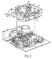
- FIG. 1 and 2 show a chassis plate 1, acting as a frame, of a magnetic tape cassette device with a head plate 3, which can be pivoted about an eccentric pivot point 5.
- the head plate 3 is U-shaped and has first and second legs 9 and 11 projecting from the ends of its base 7 in the same direction. The legs 9 and 11 engage in corner areas 12 and 13. While the first leg 9 interacts with a servo rod 14 (not shown in FIG. 1), the second leg 11 forms a functional part which cooperates with an electrical holding magnet device 15.
- the base 7 of the head plate 3 carries a magnetic head 16 and pressure rollers 17a, 17b which can be pivoted relative to the base 7.
- the pressure rollers 17a and 17b can be brought together with sound waves 18a and 18b in order to guide the magnetic tape past the magnetic head 16 in one direction or the other.
- the pivoting of the head plate 3 takes place in each case via the servo rod 14.
- This servo rod 14 acts on a spring-loaded transport lug 19 which is pivotably arranged on the leg 9.
- the head plate 3 can pivot about the eccentric pivot point 5 via the servo rod 14, and in the process rotate clockwise each time it is pushed by means of the servo rod 14.
- the electro-holding magnet device 15 consists of a magnet coil 20, into the coil cavity 21 (FIG. 3) of which legs of U-shaped, magnetically separated armature irons 22, 23 are inserted.
- the two anchor irons 22, 23 lie one above the other, the respective anchor iron legs 22a, 23a overlapping in pairs.
- the Iron yokes 22b, 23b lie on opposite coil ends 20a, 20b.
- the electric holding magnet device 15 is fixedly mounted on the chassis plate 1.
- Pole shoes 23c and 22c are formed on the free leg ends and cooperate with a first anchor plate 24 and a second anchor plate 25.
- the first anchor plate 24 is rotatably arranged on a carriage 26 by means of a pin 24a.
- This slide 26 engages with the pin 24a in a guide groove 27 of the leg 11.
- a guide pin 26b of the slide 26 can be guided along in a curved groove 28 of the functional part 11.
- the arcuate groove 28 runs at an oblique angle in the shape of an arc in the direction of the electro-holding magnet device 15.
- a spring 29 ensures that the guide pin 26b normally moves into the end region 28a of the arcuate groove 28. In this position, the slide 26 runs above the leg 11 parallel to the latter.
- the second anchor plate 25 is rotatably arranged on an arm 30 by means of a pin 25a.
- the arm 30 itself is L-shaped and has a shorter arm part 30a, which also carries the second anchor plate 25 and which is rotatable at its end 30b about an axis of rotation 31 in the direction of a double arrow 32.
- a longer arm part 30c extends parallel to that Magnetic coil 20 up to a side surface 33 of the carriage 26, where it ends in the vicinity of a nose 34 of the carriage with an oblique run-up surface 35.
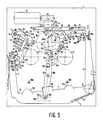
- Fig. 5 shows the so-called stand-by or rest position.
- the magnet coil 20 is de-energized and the armature plate 24 has moved away from the pole shoes 23c of the armature iron 23.
- the anchor plate 25 bears against the pole shoes 22c, since a spring 36 ensures constant contact.
- the spring 37 holds the head plate 3 pivoted counterclockwise in the rest or stand-by position. Both the magnetic head 16 and the pressure rollers 17a and 17b completely release a magnetic tape, not shown, which runs between the pressure rollers / pairs of sound waves 17a, 18a / 17b, 18b in front of the magnetic head 16. If the head plate is now to be pivoted into the playing position, ie a first working position (FIG.
- the servo rod 14 abuts the transport lug 19 in the dotted position, as a result of which the head plate 3 is pivoted clockwise.
- the magnetic coil 20 initially remains unexcited. With the Swiveling the head plate 3 clockwise also moves the leg 11 in the direction of the electro-holding magnet device 15.
- the nose 34 of the carriage 26 abuts against the inclined surface 35 of the longer arm part 30c.
- the spring 36 is dimensioned so weak that the nose 34 pushes the surface 35 and thus the longer arm part 30c counterclockwise outwards.
- the guide pin 26b remains in the end region 28a.
- the functional part 11 guides the first anchor plate 24 against the pole shoes 23c.
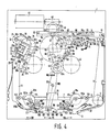
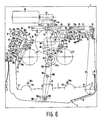
- the solenoid 20 is now energized and the armature plate 24 is held on the pole pieces 23c (FIG. 4). Thus, the head plate 3 is also held in the game position, the first working position. If the game operation is over or should be switched to fast forward or reverse, then the solenoid 20 is de-energized, and the spring 37 pivots the head plate counterclockwise back to the rest or standby position. How to approach the game position has already been described. Reaching and holding the head plate in the fast winding position (FIG. 6), ie the second working position, will now be explained. In order to get into the fast winding position (FIG. 6), the magnet coil 20 is first excited.
- the second armature plate 25 is already in contact with the pole shoes 22c, and the magnetic holding force is now added to the force of the spring 36. It has become more difficult to pivot the longer arm part 30c counterclockwise.
- the servo rod 14 runs once and swivels the head plate 3 clockwise.
- the nose 34 of the carriage 26 is now unable to pivot the longer arm part 30c away. This means that the nose 34 must avoid the surface 35 of the longer arm part 30c.
- the guide pin 26b is pushed to the other end 28b of the arcuate groove 28.
- the carriage 26 simultaneously slides in the direction of an arrow 26c with the guide pin 24a in the groove 27 in the direction of the electro-holding magnet device 15.
- the solenoid 20 is de-energized. This leads to the armature plate 24 becoming detached from the pole shoes 23c, and the spring 37 can turn the head plate 3 counterclockwise back into the rest or standby position (FIG. 5). Because of the construction just described, it must always be returned to the rest or standby position before it can be moved back to the play or fast rewind position.
- the motor 40 serves to control the movements of the head plate 3 and to drive the winding plates 42, 43.
- the sound wave motor 41 drives the sound waves 18a, 18b via a peese 44. This drive takes place via flywheels 45a, 45b.
- the peese 44 is placed in an S-shape around the oscillating disks 45a, 45b in order to bring about opposite directions of rotation of the sound waves 18a, 18b.
- the motors are controlled by a microprocessor 46 which is arranged on a circuit board 47.
- the circuit board 47 is arranged on the chassis board 1.
- the servomotor 40 acts on a servo gear 48a, which includes a worm shaft 48 and a reduction gear 49, which consists of two sub-gears 49a and 49b, and a central gear 50.
- a pivot arm 51 is pivotable about the axis 50a of the central gear 50, on which a transmission gear 52 is rotatably mounted.
- the transmission gear 52 can be pivoted via a friction clutch (not shown) between the swivel arm 51 and the central gear 50 in such a way that the transmission gear 52 can either drive one winding plate 42 or the other winding plate 43.
- the servo rod 14 can be driven in a longitudinally displaceable manner by means of a switching wheel 53.
- the switching wheel 53 belongs to a switching element 54 and is rotatably mounted on an actuating element 55 of the switching element 54.
- the switching element 54 also has a release element 56 and a positioning element 57.
- the switching element 54 is rotatably mounted about an axis 58 and is loaded clockwise by means of a resilient arm 59.
- a control switch 60 is arranged on the chassis plate 1, the switching lug 61 of which can cooperate with the positioning member 57 of the switching element 54 and a switching extension 62 of the servo rod 14.
- the switching lug 61 takes no load a middle position from which it can be pivoted away on two sides. In the middle position, the switch 60 is open, with the switching lug 61 pivoted away to the side, the switch 60 is closed. With each new movement of the switching lug 61, the switch 60 emits a signal.
- the positioning member 57 has a guide pin 63, the position of which relative to the servo rod 14 is determined by the latter.
- a first determining position is shown in FIGS. 3, 4 and 6, while the second determining position is shown in FIG. 5.
- the servo rod has an edge 64 for positioning in the second position.
- the first position is determined by a groove 65 in the servo rod 14.
- the control rod thus determines the position of the switching element 54 between the start of the servo operation and the end of the servo operation, either directly via the groove 65 or indirectly via the control member 73, where the drive in Play mode or fast reel mode passes.
- the three-armed switching element 54 has a wide fork 66 on its release member 56, which cooperates with a limiting pin 67 on the swivel arm 51.
- Two grooves 68, 69 are provided on the chassis plate 1.
- the groove 68 is L-shaped, while the groove 69 is designed as an elongated hole in the direction of displacement of the servo rod 14.
- the direction of displacement of the servo rod is indicated by a double arrow 70.
- the groove 68 has a groove arm 68a in the direction of the double arrow 70 and an arm 68b running perpendicular thereto in a direction perpendicular to the double arrow 70. These are vertical Direction is indicated by an arrow 71.
- Guide pins 72a, 72b of a control member 73 engage in the grooves 68 and 69.
- This control member 73 is forced by means of a spring 74 in two directions, once in the direction of a control lug 75 which is firmly connected to the free end of the first leg 19.
- the control lug 75 is located in the vicinity of the transport lug 9 the second direction in which the spring 74 urges the control member 73 is the direction indicated by the arrow 71.
- a slope 76 is provided on the control member 73, which can cooperate with a slope 55a on the actuator 55.
- the control member 73 is L-shaped with a short arm extension 77 which carries a travel pin 78. This driving pin interacts with a set up 79 in the servo rod 14. This furnishing backdrop consists of two tracks 79a, 79b, which are connected via a Schadow latch 80.
- This Schadow pawl 80 is designed to be resilient in such a way that the traction pin can travel through it in the direction indicated by an arrow 81, but not in the opposite direction. After the travel pin 78 has entered the web 79b through the Schadow pawl 80, it can no longer return to the Schadow pawl, but must run in the web 79b, which runs in the direction of the double arrow 70.
- the servo rod 14 is provided with a coupling member 82, which establishes the connection to an elevator slide 83.
- This elevator slide 83 has an extension 84, which can press against the coupling member 82 on one side, in the direction of an arrow 85.
- the direction of the arrow 85 agrees with the direction of insertion of a cassette 86 into a loading mechanism 87 which the lift slide 83 belongs to.
- the loading mechanism 87 has a lift shaft 88 which receives the cassette 86.
- the lift slide 83 is guided in a sliding guide 89 so as to be longitudinally displaceable in the direction of the double arrow 70.
- the slide guide 89 is part of a plastic part 90, which is connected to the chassis plate 1 in a manner not shown.
- the lifter slide 83 is somewhat U-shaped with a long leg 91, a base 92 and a short leg 93.
- two oblique scenes 94 are provided, in which pins 95 of the elevator shaft 88 are led.
- the short leg 93 is also provided with an oblique backdrop 96 which interacts with a tab 97 of the elevator shaft.
- an over-center spring 98 is provided, which is supported on the one hand on the plastic part 90 and on the other hand on the long leg 91 of the elevator slide 83.
- the plastic part 90 has a horizontal edge 90a, which is delimited by a vertical edge surface 90b.
- a further vertical edge surface 90c extends parallel to the vertical edge surface 90b.
- the distance between the two vertical edges 90b and 90c corresponds to the distance between the pins 95, the pins 95 being able to move along the vertical edge surfaces 90b and 90c.
- Fig. 1 also shows that the swivel arm 51 is arranged between the winding plates, which is the transmission gear 52 stores.
- the swivel arm 51 has a joint 99 which is engaged by an adjusting lever 100 which can pivot about a tilting bearing 101.
- a fixed tooth segment 102 is arranged, on which the transmission gear 52 can roll.
- the transmission gearwheel has a partial gearwheel 52a on its underside.
- the actuating lever 100 remote from the joint 99 the actuating lever 100 carries a pin 103 which is displaceable to a limited extent in an elongated hole 104.
- the elongated hole 104 is located in a slide 105, which has pins 106 which are displaceable in elongated holes 107 of the chassis plate, specifically parallel to the double arrow 70.
- Eccentric discs 109 which are connected to toothed segments 110, can be pivoted on the chassis plate 1 about axes 108. These toothed segments 110 work together with toothed racks 111 of the slide 105.
- the pin 103 can move the slide 105 in one or the other direction of the double arrow 70 after reaching one or the other end edge of the elongated hole 104 .
- the eccentric discs 109 are rotated.
- the pressure rollers 17a, 17b are mounted in brackets 112a, 112b, which in turn can be pivoted about axes 113.
- the axes 113 are arranged on the head plate 3.
- the brackets 112a and 112b have pins 114 which can run over the surfaces of the eccentric discs 109.
- the brackets 112a and 112b are spring-loaded with the aid of springs 115a, 115b in the direction of the sound waves 18a, 18b.
- the springs 115a and 115b also always press the pins 114 against the eccentric discs 109.
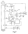
- Figure 7 shows a circuit device used to control all drive functions.
- a motor controller 46a is assigned to the microprocessor 46.
- the servo motor 40 of the drive is operated via a bridge power amplifier, consisting of two power amplifiers 208 and 209, which are controlled by the microprocessor 46 via lines 201 and 202 and which are switched through to the servo motor 40 via lines 201a and 202a.
- the motor controller 46a provides a switchover of the voltage supply of the power amplifiers 208 and 209 between 2 V and 12 V.
- the switchover is carried out with the aid of switches 206 and 207, the switchover of which takes place via a control line 203 of the microprocessor.
- the servo motor 40 is selectively switchable to the servo rod 14 or one of the winding plates 42, 43 via a clutch 40a, which is indicated by a dashed line and consists of the gear 53 and the switching element 54 Initiate switching lug 61 of switch 60. Each time the switch 60 is triggered, pulses are generated which are supplied to the microprocessor 46 via the control line 205.
- the current flowing through the servo motor 40 and the power amplifiers 208 and 209 is supplied to a grounded resistor 210 via lines 217 and 218. Since the current flowing from the servomotor 40 via the lines 201a and 218 is pulsating due to commutation interruptions, a pulsating voltage drop results at the switching point 219. These needle-like pulses become via a differentiating element 211 and a monoflop 212 Reckeck pulses processed and supplied to the microprocessor 46. This microprocessor 46 counts the pulses and adds them. The added impulses can be displayed on a display 213 in the form of a tape length display and direction of rotation display.
- Keys 214 are provided with which individual functions of the drive can be determined manually. These include, for example, reversing the tape direction, fast forwarding and rewinding, and cassette ejection.
- the keys 214 are all connected to the microprocessor 46, which then controls the function desired by pressing the key.
- the microprocessor controls a power amplifier 216, which controls the electro-holding magnet 15 in such a way that the head plate 3 can be held in the play position or in a fast winding position.
- the switch 60 is an on / off switch, the activation and deactivation of which are recognized by the microprocessor 46 as defined switching signals.
- the microprocessor recognizes that the switching lug 61 becomes free when switched on and moves automatically into its central position and that the switching lug 61 is pushed away from the central position when switched off.
- the position switched on and switched off provides information about the switching point at which control rod 14 and switching element 54 are currently located within the movement sequence of the servomechanism.
- the microprocessor counts the square-wave pulses emitted by the monoflop 212 during servo operation and uses them to form an actual-time inter between the individual switching points vall in which the servomechanism has moved from one switching point to the other switching point.
- the time intervals that the Servomechanis now needs to get from one switching point to the other are stored in the microprocessor.
- the microprocessor constantly checks whether these time intervals are also observed. If the target intervals are not maintained within a certain tolerance, the microprocessor automatically switches the servomotor 40 to the direction of ejection rotation.
- the microprocessor is also designed in such a way that it recognizes at which function point the servomechanism was located in the last switching signal received previously.
- a switching pulse formed when opening is evaluated by the microprocessor 46. This recognizes that the switch 60 is open; it sets the motor control inputs 201, 202 and 203 so that the servo motor 40 can start up with a voltage of 12 V in the desired servo feed rotation direction.
- the power amplifiers 208 and 209 apply the full 12 V supply voltage to the servo motor 40.
- the mechanically coupled servo motor 40 now moves the servo rod 14 further in the pull-in direction 85.
- the attachment 84 now no longer needs to take the coupling member 82 along and the lift slide travels alone by means of the force of the dead center spring in the insertion direction 45, and so far until the pins 95 can slide down along the vertical edge surfaces 90b and 90c, the pins 95 also sliding downwards in the oblique scenes 94.
- the flap 97 slides down on the backdrop 96. This downward sliding is ended when the lift slide 83 has reached its rear end position according to FIG. 2. In this position, the elevator shaft 88 has reached its rear and lower positions, and the cassette 86 is placed on winding mandrels 116, 117.
- the servo motor gear 48a has switched off the winding plate drive simultaneously with the engagement of the servo (control rod) drive.
- the servo motor gearbox is therefore a two-function gearbox which works on the control rod 14 in the servo mode and on one of the winding plates 42, 43 in the fast winding or play mode.
- the drive of the servo rod 14 via the switching wheel 53 is self-retracting in the direction of extension counter to the arrow 85.
- the drive with the switching wheel 53 is self-releasing. This means that the ratchet wheel by itself when the servo rod 14 moves in, when the control member 73 does not specify a travel limit can come out of engagement with the central gear.
- the self-retracting direction of the switching wheel 53 ensures that the guide pin 63 remains on the corner 125 without being guided in a particular manner.
- the control rod 14 moves to the right in the play position according to FIG. 4, as far to the right as is indicated in FIG. 4 by dashed lines.
- the servo rod 14 has pivoted the head plate 3 into its play position in the manner already described, as can be seen from FIGS. 1 and 4.
- the switching shoulder 62 of the servo rod 14 abuts the switch nose 61 and closes the switch 60.
- the closing triggers a switching pulse which is supplied to the microprocessor 46 via the line 205 becomes.
- the microprocessor recognizes the first reversing switching point and controls the inputs 201 and 202 so that the power amplifiers 208 and 209 stop the motor 40 after a safety overflow time of approximately 150 msec and start in the opposite direction of rotation.
- an overload clutch not shown, is inserted between the gear wheels 49a and 49b.
- the microprocessor simultaneously switches on the holding magnet device 15. The head plate is thus held in the game position.
- the microprocessor has monitored the actual time interval between the start switching point and the first reversing switching point with the target time interval known to it. If the actual-time interval had exceeded the target-time interval, the microprocessor would have automatically reset the servo motor 40, ie reversed in the discharge direction.
- the microprocessor 46 starts the servomotor 40 in the opposite direction.
- the servo rod 14 starts again in the opposite direction.
- the switch 60 opens; it emits a switching pulse that the microprocessor recognizes as a second reversing switching point.
- the microprocessor notes that the servo drive from the second reversing switching point is on the way to the servo end switching point, in which it is switched to fast winding or play mode. Shortly before reaching the servo limit switch point, the control member 73 and the switching element 54 have separated from one another. Due to the force of the spring 59, the switching element 54 pivots clockwise, the limiting pin 67 being released by the wide fork 66.
- the swivel lever 51 can place the transmission gear 52 against one of the winding plates 42, 43.
- the servomotor gear 48a is thus switched over to the winding plate drive when the switching element 54 is pivoted from the servo operation (the switching element 54 has guided the switching wheel 52 away from the central wheel 50; this position is indicated in FIG. 7 with the mechanical coupling 40a shown in broken lines).
- the pressure roller 17a / 17b was applied in the pulling direction to the associated shaft 18a / 18b via the pivot lever 51 and the adjusting lever 100.
- the positioning member 57 abuts the switch nose 61 and the switch 60 is closed.
- the switch outputs a switching pulse to the microprocessor 46 via the line 205.
- the microprocessor 46 has again compared the actual time interval with the desired time interval and has determined a correct desired time interval. The servo process can therefore continue.
- the microprocessor 46 switches to tighten the belt, the servo motor for e.g. B. 25 msec to 12 V without current limitation. Then switch to 12V with current limitation for 250 msec. In this time interval, the microprocessor switches on the sound wave motor 41.
- the game process starts with high torque. After the 250 msec has elapsed, the microprocessor switches the servo motor 40 from 12 V to 2 V via line 203 and switches 206 and 207.
- the servo motor 40 continues to rotate at a lower torque.
- the servomechanism is now switched off and the drive plays a cassette.
- the adjusting lever 100 For pressure roller adjustment, the adjusting lever 100 has moved the slide 105 in the direction of an arrow 120 to the left.
- the toothed racks 111 have rotated the eccentric discs 109 clockwise via the toothed segments 110.
- the pin 114 of the bracket 112a on the right has left the surface 121 of the eccentric 109 and has run against an edge 122, the spring 115a constantly pressing the pin 114 against the edge 122.
- the pressure roller 17a has thus been placed against the shaft 18a.
- the running of the pin 114 from the surface 121 over a corner 123 to the edge 122 has at the same time the result that the displacement of the slide 105 previously initiated by the actuating lever 100 in the direction of the arrow 120 has now been taken over by the pin 114.
- the electrical control of the drive always takes place via a switch 60 and the microprocessor 46. Control commands from the outside go to the microprocessor 46 via keys 214 or the like.
- the end of the tape ie the stopping of the motor 40, is also detected by the microprocessor 46.
- the current flowing through the servo motor 40 also flows through a resistor 210 (FIG. 7).
- the current pulsating through resistor 210 causes a pulsating voltage drop across resistor 210.
- the voltage pulses are differentiated at a differentiator 211.
- a monoflop 212 is triggered with the differentiated voltage.
- the trigger pulses are fed via line 204 to the microprocessor 46, which counts the pulses.
- the microprocessor 46 detects the tape standstill and reverses the direction of motor rotation by reversing the power amplifiers 208, 209 via the lines 201 and 202.
- This reversal of the direction of rotation causes the adjusting lever 100 to initially adjust the slide 105 in the direction of an arrow 124 until the pin 114 on the left eccentric disk 109 over the corner 123 has run and the pin 114 has then taken over the further displacement of the slide 105 in the direction of the arrow 124 via the edge 122.
- the pressure roller 17a has become detached from the tone shaft 18a, while the pressure roller 17b has placed itself against the tone shaft 18b.
- the transmission gear 52 is swung over from the winding plate 42 to the winding plate 43.
- the switches 206 and 207 are briefly switched to 12 V by the microprocessor in order to accelerate the switching process.
- the drive can be switched off at any time during servo operation; it then remains in the off position when the top plate has fallen off.
- the servomotor 40 is first switched on in the ejection direction for a reset.
- the control rod 14 moves to the left to the next switching point and recognizes it. From this point of view, the servo processes run in the manner already described.
- the pulses emitted by the monoflop 212 via the line 204 to the microprocessor 46 are counted, added up and shown on the display.
- the pulse count includes tape length and direction of rotation display.
- the servo motor 40 drives a servo motor gear 48a, which is designed as a two-function gear with adapted reduction gear trains for the control rod drive and the winding plate drive.
- the efficiency of the reduction gear for the winding plate drive is optimized so that the speed-torque curve of the servo motor 40, which is effective on the winding plate, adapts so far to the winding torque-winding diameter curve on the winding plate that the veröaif that the winding plate can be driven without interposing a slip clutch.
- the gear between the servo motor 40 and the winding plate 42 or 43 consists of the worm shaft 48, the reduction gear 49, which consists of the two partial gears 49a and 49b connected via an overload clutch, the central gear 50 and the transmission gear 52. These are therefore all gears between the shaft of the servo motor 40 and the winding plates 42 or 43.
- the winding torque on the winding reel changes when the winding diameter changes or the winding speed changes.
- the winding torque is high and the speed of the winding winding plate is high.
- the torque of a DC servo motor is high at low speed and low at high speed.
- the solid characteristic curve n / M mo shows that the engine speed n m decreases approximately linearly with increasing engine torque.
- the winding torque M wi required on the winding plate is also increasing, the characteristic curve n wi / M wi being curved.
- the position of the characteristic curves can be approximated to one another in a central area by adjusting the gearbox efficiency, so that, in the end, an approximately constant tensile force F B , measured in cN, measured across the diameter of the tension winder on the winding winder. is obtained. This means that a slip clutch that compensates for the torque differences can be dispensed with.
Landscapes
- Engineering & Computer Science (AREA)
- Computer Hardware Design (AREA)
- Toys (AREA)
- Control Of Position Or Direction (AREA)
- Adjustment Of The Magnetic Head Position Track Following On Tapes (AREA)
- Automatic Tape Cassette Changers (AREA)
Abstract
Die Erfindung bezieht sich auf ein Laufwerk für ein Magnetbandkassettengerät mit einem Tonwellen-Antriebsmotor und mit einer von einem Servomotor (40) über ein Servogetriebe (48a) angetriebenen, hin und zurück längsverschieblichen Servostange (14), die auf ihrem Verschiebeweg Funktionsteile des Gerätes, wie eine Kopfplatte (3), einen Lademechanismus (87) und einen Umschaltmechanismus steuert unter Zuhilfenahme eines Schaltsignale empfangenden Mikroprozessors (46) und einer Steuervorrichtung (46a) für den Servomotor (40) ,wobei
- a) ein Schaltmittel (60), das dem Mikroprozessor (46) die Schaltsignale zuleitet, schaltbar ist von der Steuerstange (14) und von einem mechanischen Schaltorgan (54), das zwar von der Steuerstange (14) unabhängige Bewegungen ausführen kann, dessen Stellung gegenüber der Steuerstange (14) jedoch während des Servobetriebes von der Steuerstange (14) zeitweise bestimmt wird,
- b) der Mikroprozessor (46) aus dem bei jedem mechanischen Anstoßen durch Steuerstange (14) oder Schaltorgan (54) empfangenen Schaltsignal die momentanen räumlichen Stellungen des Schaltmittels (60), der Steuerstange (14) und/oder des Schaltorgans (54) ermittelt aus der Stellung des Schaltmittels (60) und dem gespeicherten letzten, zuvor erhaltenen Schaltsignal,
- c) der Mikroprozessor (46) die Schaltsignale des Schaltmittels (60) umsetzt in Steuerbefehle für den Servomotor (40) für Servo- und Wickeltellerantrieb, den Tonwellen-Antriebsmotor (41) und eine Haltemagnetvorrichtung (15) für die Kopfplatte (3), die in der Spiel- bzw. Schnellspulstellung mittels dieser Haltemagnetvorrichtung (15) gehalten wird.

- a) a switching means (60), which supplies the switching signals to the microprocessor (46), can be switched by the control rod (14) and by a mechanical switching element (54), which can perform independent movements of the control rod (14), its position compared to the control rod (14), however, is temporarily determined by the control rod (14) during servo operation,
- b) the microprocessor (46) determines the instantaneous spatial positions of the switching means (60), the control rod (14) and / or the switching element (54) from the switching signal received with each mechanical trigger by the control rod (14) or switching element (54) the position of the switching means (60) and the stored last switching signal previously received,
- c) the microprocessor (46) converts the switching signals of the switching means (60) into control commands for the servo motor (40) for servo and winding plate drive, the sound wave drive motor (41) and a holding magnet device (15) for the head plate (3) is held in the play or fast winding position by means of this holding magnet device (15).
Description
Die Erfindung bezieht sich auf ein Laufwerk für ein Magnetbandkassettengerät mit einem Tonwellenantriebsmotor und mit einer von einem Servomotor über ein Servogetriebe angetriebenen, hin und zurück längsverschieblichen Servostange, die auf ihrem Verschiebeweg Funktionsteile des Gerätes, wie eine Kopfplatte, einen Lademechanismus und einen Umschaltmechanismus steuert unter Zuhilfenahme eines Schaltsignale empfangenden Mikroprozessors und einer Steuervorrichtung für den Servomotor.The invention relates to a drive for a magnetic tape cassette device with a Tonwellenantriebsmotor and with a servomotor driven by a servo gear, back and forth longitudinally displaceable servo rod, which controls functional parts of the device, such as a head plate, a loading mechanism and a switching mechanism with the aid of its displacement path of a switching signal receiving microprocessor and a control device for the servo motor.
Bei Magnetbandgeräten, die zum Abspielen von Bandkassetten, insbesondere sogenannten Compact-Kassetten, eingerichtet sind, ist es bekannt, den Magnetkopf das Laufwerkes gegenüber dem in der Kassette angeordneten Magnetband zu verstellen. Dieses Verstellen findet statt durch die Verstellung einer den Magnetkopf tragenden Kopfplatte. Üblicherweise ist auch ein Lademechanismus vorgesehen, in den eine Compact-Kassette einschiebbar ist und der die eingeschobene Compact-Kassette dann in eine Spielstellung überführt. Dazu wird eine Lift-Vorrichtung eingesetzt. Die Bandlaufrichtung wird bei sogenannten Autoreverse-Geräten mit zwei Spielrichtungen von der Motor drehrichtung bestimmt, wobei Druckrollen gegen eine erste oder eine zweite Tonwelle angedrückt und die Wickelteller für das Magnetband abwechselnd in der einen oder anderen Richtung angetrieben werden.In the case of magnetic tape devices which are set up to play tape cassettes, in particular so-called compact cassettes, it is known to adjust the magnetic head of the drive in relation to the magnetic tape arranged in the cassette. This adjustment takes place through the adjustment of a head plate carrying the magnetic head. A loading mechanism is usually also provided, into which a compact cassette can be inserted and which then transfers the inserted compact cassette into a playing position. A lift device is used for this. The tape running direction is so-called autoreverse devices with two directions of the motor determined direction of rotation, with pressure rollers pressed against a first or a second shaft and the winding plate for the magnetic tape are driven alternately in one or the other direction.
Aus der DE 33 15 822.3 C2 (PHD 83-040) ist darüber hinaus ein Magnetbandgerät bekannt, bei dem mittels eines Motors eine Servostange hin und zurück antreibbar ist in Längsrichtung der Stange, um Lade- bzw. Umschaltfunktionen zwischen den Laufrichtungen auszuführen. Zur Ausübung dieser Funktionen muß die Servostange immer in eine Referenz-Endstellung gefahren werden, aus der heraus dann die verschiedenen Funktionen abgeleitet werden. Dies ist sowohl mechanisch als auch elektrisch aufwendig und erfordert viel Zeit zwischen dem Außerbetriebsetzen einer Spielfunktion und dem erneuten wieder in Betrieb nehmen in einer anderen Funktion.DE 33 15 822.3 C2 (PHD 83-040) also discloses a magnetic tape device in which a servo rod can be driven back and forth in the longitudinal direction of the rod by means of a motor in order to carry out loading or switching functions between the running directions. To perform these functions, the servo rod must always be moved to a reference end position, from which the various functions can then be derived. This is both mechanically and electrically complex and requires a great deal of time between the decommissioning of a game function and the restarting in another function.
Bekannt ist es auch, mittels eines Motors die Wickelteller des Laufwerkes zum Zwecke des Aufwickelns unmittelbar anzutreiben. Ein derartiger Antrieb erspart zwar Rutschkupplungen, ist aber als getrennte Antriebseinheit aufwendig.It is also known to directly drive the winding plate of the drive by means of a motor for the purpose of winding. Such a drive saves slip clutches, but is complex as a separate drive unit.
Aufgabe der Erfindung ist es, einen den Geräteaufbau vereinfachenden Servo- und Steuermechanismus für ein Magnetbandkassettengerät zu schaffen, bei dem die Steuerungs- und Regelungsfunktionen von möglichst wenigen teils elektrischen, teils mechanischen Bauteilen übernommen werden.The object of the invention is to provide a servo and control mechanism for a magnetic tape cassette device which simplifies the construction of the device and in which the control and regulation functions are taken over by as few as possible partly electrical and partly mechanical components.
Die gestellte Aufgabe ist erfindungsgemäß dadurch gelöst, daß
- a) ein Schaltmittel, das dem Mikorprozessor die Schaltsignale zuleitet, schaltbar ist von der Steuerstange und von einem mechanischen Schaltorgan, das zwar von der Steuerstange unabhängige Bewegungen ausführen kann, dessen Stellung gegenüber der Steuerstange jedoch während des Servobetriebes von der Steuerstange zeitweise bestimmt wird,
- b) der Mikroprozessor aus dem bei jedem mechanischen Anstoßen durch Steuerstange oder Schaltorgan empfangenen Schaltsignal die momentanen räumlichen Stellungen des Schaltmittels der Steuerstange und/oder des Schaltorgans ermittelt aus der Stellung des Schaltmittels und dem gespeicherten letzten, zuvor erhaltenen Schaltsignal,
- c) der Mikroprozessor die Schaltsignale des Schaltmittels umsetzt in Steuerbefehle für den Servomotor für Servo-und Wickeltellerantrieb, den Tonwellen-Antriebsmotor und eine Haltmagnetvorrichtung für die Kopfplatte, die in der Spiel- bzw. Schnellspulstellung mittels dieser Haltemagnetvorrichtung gehalten wird.
- a) a switching means which feeds the switching signals to the microprocessor, can be switched by the control rod and by a mechanical switching element which can perform movements independent of the control rod, but whose position relative to the control rod is temporarily determined by the control rod during servo operation,
- b) the microprocessor determines the instantaneous spatial positions of the switching means of the control rod and / or the switching element from the switching signal received by the control rod or switching element each time it is mechanically triggered, from the position of the switching means and the stored last, previously received switching signal,
- c) the microprocessor converts the switching signals of the switching means into control commands for the servo motor for servo and winding plate drive, the sound wave drive motor and a holding magnet device for the head plate, which is held in the play or fast winding position by means of this holding magnet device.
Alle nach dem Starten bis zum Spielbeginn anfallenden Laufwerksfunktionen, sowohl mechanischer als auch elektrischer Art gehen von der Steuerstange unmittelbar mechanisch oder elektrisch über das Schaltmittel aus, das auf den Mikroprozessor arbeitet. Mechanisch übernehmen die Steuerstange und das Schaltorgan die Verstellung der Kopfplatte und die Umstellung des Wickelteller- und Servoantriebes. Dabei ist auch wichtig, daß die Steuerstange wiederum auch bestimmt, wann das Schaltorgan von ihr unabhängige Bewegungen ausführen kann.All drive functions that occur after starting up to the start of the game, both mechanical and electrical, start directly from the control rod mechanically or electrically via the switching means that works on the microprocessor. The control rod and the switching element mechanically take over the adjustment of the head plate and the changeover of the winding plate and servo drive. It is also important that the control rod in turn also determines when the switching element can perform independent movements.
Die Mikroprozessor ist so programmiert, daß er nicht nur Schaltsignale des Schaltmittels elektrisch in Steuerbefehle umwandelt; er ist auch so eingerichtet, daß er jederzeit weiß oder durch Anfahren des nächsten, zur Schaltung von Funktionen vorgesehenen Schaltpunktes eine Selbstorientierung vornimmt, um sich zu vergewissern, in welchem Servofunktionsstadium sich das Laufwerk gerade befindet. Hierzu bedient er sich der Aussage des in ihm gespeicherten letzten, zuvor erhaltenen Schaltsignals und des neuen Schaltsignals, das eine Aussage über die derzeitige Stellung des Schaltmittels macht. Auf diese Weise kann, wenn beispielsweise der Strom ausgeschaltet wurde, der Mikroprozessor nach dem erneuten Stromanschalten in irgendeiner Phase des Servobetriebes über die Steuerstange einen benachbarten Schaltpunkt finden und daraus dann die erforderlichen Steuerbefehle für den Servomotor, den Tonwellen-Antriebsmotor und die Haltemagnetvorrichtung abgeben.The microprocessor is programmed so that it not only Switching signals of the switching means are electrically converted into control commands; it is also set up in such a way that it knows at any time or takes a self-orientation by moving to the next switching point provided for switching functions, in order to ensure that the servo function stage the drive is currently in. For this purpose, he uses the statement of the last, previously received switching signal stored in him and the new switching signal, which makes a statement about the current position of the switching means. In this way, if, for example, the power has been switched off, the microprocessor can find an adjacent switching point via the control rod in any phase of the servo operation and can then issue the necessary control commands for the servo motor, the sound wave drive motor and the holding magnet device.
Diese Aufteilung in mechanische und elektrisch-elektronische Funktionsüberwachung erlaubt für die einzelnen Laufwerksfunktionen kurze Zugriffszeiten, die für den Komfort eines Gerätes von großer Bedeutung sind. Die Zahl der Bauteile ist stark reduziert.This division into mechanical and electrical-electronic function monitoring allows short access times for the individual drive functions, which are of great importance for the convenience of a device. The number of components is greatly reduced.
Nach einer weiteren Ausgestaltung der Erfindung ist vorgesehen, daß das Schaltmittel ein Schalter ist, der beim Öffnen und beim Schließen mittels einer Schaltnase ein Schaltsignal abgibt. Ein solcher Schalter ist einfach und funktionssicher; das Öffnen und Schließen kann vom Mikroprozessor erkannt werden.According to a further embodiment of the invention it is provided that the switching means is a switch which emits a switching signal when opening and closing by means of a switching lug. Such a switch is simple and reliable; the opening and closing can be recognized by the microprocessor.
Nach einer weiteren Ausgestaltung der Erfindung ist vorgesehen, daß der Mikroprozessor über die Steuervorrichtung die Drehrichtung des Servomotors vorgibt und die Spannungsversorgung des Servomotors umschaltet zwischen einer hohen Versorgungsspannung für den Betrieb des Lade- und Servomechanismus sowie das Schnellspulen und einer niedrigen Versorgungsspannung für den Wickeltellerantrieb während des Spielbetriebes. Die hohe Versorgungsspannung des Servomotors sorgt dafür, daß die Servobewegungen rasch durchführbar sind und das Umspulen einer Kassette in relativ kurzer Zeit abgeschlossen werden kann. Die niedrige Versorgungsspannung ermöglicht mit demselben Servomotor den Antrieb des einen oder anderen Wickeltellers.According to a further embodiment of the invention it is provided that the microprocessor specifies the direction of rotation of the servo motor via the control device and the Power supply of the servo motor switches between a high supply voltage for the operation of the charging and servomechanism as well as fast winding and a low supply voltage for the winding plate drive during play. The high supply voltage of the servo motor ensures that the servo movements can be carried out quickly and the rewinding of a cassette can be completed in a relatively short time. The low supply voltage enables the drive of one or the other winding plate with the same servo motor.
Nach einer weiteren Ausgestaltung der Erfindung ist vorgesehen, daß die Steuervorrichtung mit in den Motorzuleitungen vorgesehenen Brückenleistungsverstärkern versehen ist. Derartige Brückenleistungsverstärker bieten eine bequemen Servomotor.According to a further embodiment of the invention it is provided that the control device is provided with bridge power amplifiers provided in the motor feed lines. Such bridge power amplifiers offer a convenient servo motor.
Nach einer weiteren Ausgestaltung der Erfindung ist vorgesehen, daß die Steuervorrichtung mit einem Impulsdetektor versehen ist, der Betriebsfunktionen des Servomotors über die Spannungsversorgung der Brückenleistungsverstärker detektiert. Die Detektierung erfolgt dabei in der Weise, daß die Spannungsversorgungsleitungen der Brückenleistungsverstärker auf ein Differenzierglied geschaltet sind, das aus der pulsierenden Gleichspannung des Motors zählbare Impulse bildet. Ein mit Gleichstrom betriebener Servo-Kommutatormotor unterbricht den durch ihn fließenden Strom im Zeitpunkt der Kommutierung. Diese Kommutierungsunterbrechungen werden zur Bildung von zählbaren Impulsen genutzt.According to a further embodiment of the invention, it is provided that the control device is provided with a pulse detector which detects operational functions of the servo motor via the voltage supply of the bridge power amplifiers. The detection takes place in such a way that the voltage supply lines of the bridge power amplifiers are connected to a differentiator which forms countable pulses from the pulsating DC voltage of the motor. A servo commutator motor operated with direct current interrupts the current flowing through it at the time of commutation. These commutation interruptions are used to form countable pulses.
Nach einer weiteren Ausgestaltung der Erfindung ist vorge sehen, daß die Impulse des Differenzgliedes über ein Monoflop dem Mikroprozessor zugeführt werden, der die Impulse zählt und daraus Zeitwerte bildet. Solche Zeitwerte können der Geschwindigkeitsüberwachung des Motors, der Bandlängenzählung oder der Bandstop-Detektion dienen.According to a further embodiment of the invention is pre see that the pulses of the differential element are fed via a monoflop to the microprocessor, which counts the pulses and forms time values from them. Such time values can be used for speed monitoring of the motor, the belt length counting or the belt stop detection.
Nach einer weiteren Ausgestaltung der Erfindung ist vorgesehen, daß der Mikroprozessor die Ist-Zeiten zwischen aufeinanderfolgend empfangenen Schaltsignalen ermittelt und mit einer gespeicherten Soll-Zeiten vergleicht und daß der Mikroprozessor den Servomotor bei unzulässigen Zeitdifferenzen auf die Auswerfdrehrichtung umschaltet. Damit kann der Mikroprozessor Überwachungsfunktionen übernehmen, indem er beispielsweise feststellt, ob die Steuerstange vom Beginn ihrer Bewegung von einem Schaltpunkt des Schaltmittels bis zum Erreichen des nächstfolgenden Schaltpunktes eine gewisse Soll-Zeit überschreitet. Soll-Zeit-Überschreitungen können auf Fehler hindeuten. Im Falle von Soll-Zeit-Überschreitungen schaltet der Mikroprozessor den Servomotor in Auswerf-(Eject)-Richtung um.According to a further embodiment of the invention, it is provided that the microprocessor determines the actual times between successively received switching signals and compares them with a stored target times and that the microprocessor switches the servo motor to the direction of ejection in the event of impermissible time differences. The microprocessor can thus take over monitoring functions, for example by determining whether the control rod exceeds a certain desired time from the start of its movement from a switching point of the switching means to the reaching of the next switching point. Target time overruns can indicate errors. If the target time is exceeded, the microprocessor switches the servo motor in the eject direction.
Nach einer weiteren Ausgestaltung der Erfindung ist vorgesehen, daß das mechanische Schaltorgan jeweils am Ende des Servobetriebes zum Einleiten des Spielbetriebes von der Steuerstange zur Ausführung eigener Bewegungen freigegeben wird, wobei infolge der eigenen Bewegung des Schaltorgans von diesem elektrisch durch das Anstoßen des Schaltmittels die Einschaltung des Tonwellen-Antriebsmotors sowie die Absenkung der Versorgungsspannung des Servomotors und mechanisch die Umschaltung des Servomotorgetriebes von dem Servoantrieb (Steuerstange) auf dem Bandantrieb (Wickelteller) bewirkt wird. Am Ende einer Servobewegung des Servomechanismus fallen zur Aufnahme des Spielbetriebes mehrere mechanische und elektrische Schaltfunktionen an. Elektrisch ist der Servomotor für den Spielbetrieb vorzubereiten, muß der Tonwellen-Antriebsmotor in Betrieb gesetzt werden und muß eine Stummschaltung des Verstärkers, falls dieser nicht angeschaltet werden muß, aufgehoben werden. Mechanisch muß ein Wechsel des Servomotorgetriebes vom Servoantrieb auf den Wickelantrieb vorgenommen werden. Dies kann bei dem Geräteaufbau allein über das Schaltorgan bewerkstelligt werden.According to a further embodiment of the invention, it is provided that the mechanical switching element is released at the end of the servo mode for initiating the play mode from the control rod to carry out its own movements, with the switching element being electrically switched on by the switching means as a result of the switching element's own movement Tonwelle-drive motor and the lowering of the supply voltage of the servo motor and mechanically switching the servo motor gear from the servo drive (control rod) on the belt drive (winding plate) is effected. At the end of a servo movement of the Servomechanism have several mechanical and electrical switching functions to start the game operation. Electrically, the servo motor must be prepared for play, the sound wave drive motor must be started and the amplifier must be muted if it does not have to be switched on. Mechanically, the servomotor gear must be changed from the servo drive to the winding drive. This can be done in the device structure alone via the switching element.
Nach einer weiteren Ausgestaltung der Erfindung ist vorgesehen, daß das Servomotorgetriebe als Zweifunktionsgetriebe mit angepaßten Untersetzungsgetriebezügen für den Steuerstangenantrieb und den Wickeltellerantrieb ausgebildet ist und daß der Wirkungsgrad des Untersetzungsgetriebezuges für den Wickeltellerantrieb derart ausgelegt ist, daß sich der am Wickelteller wirksame Drehzahl-Drehmomentverlauf des Servomotors so weit an den Wickeldrehzahl-Wickelmomentverlauf anpaßt, daß die Bandzugkraft am aufwickelnden Wickelteller über der Wickeldrehzahl bzw. dem wechselnden Wickeldurchmesser weitgehend gleich ist, wobei als Parameter für die Anpassung die Kennlinie n/Mmo des Servomotors, das Übersetzungsverhältnis und der Wirkungsgrad mit der Zahnradmaterialpaarung herangezogen werden. Durch eine solche Optimierung wird die Einsparung einer Rutschkupplung zwischen Antrieb und Wickelteller möglich. Damit ist ein Störfaktor aus dem Bandbetrieb entfernt, weil Rutschkupplungen wegen der enormen Temperaturdifferenzen in einem Laufwerk für ein Autoradio nur schwer beherrschbar sind. In einem Autoradio muß mit Umfeldtemperaturen von beispielsweise -30oC bis +80oC gerechnet werden. Es gibt keine Rutschkupplung, die diesen extremen Anforderungen gerecht wird. Die Einsparung der Rutschkupplung führt zu einer wesentlichen Verbesserung der Bandlaufqualität.According to a further embodiment of the invention, it is provided that the servo motor transmission is designed as a two-function transmission with adapted reduction gear trains for the control rod drive and the winding plate drive and that the efficiency of the reduction gear train for the winding plate drive is designed such that the speed-torque curve of the servo motor acting on the winding plate is such adapts widely to the winding speed-winding torque curve so that the tape tensile force on the winding reel over the winding speed or the changing winding diameter is largely the same, the parameters n / M mo of the servo motor, the transmission ratio and the efficiency with the gear material pairing being used as parameters for the adaptation will. Such an optimization makes it possible to save a slip clutch between the drive and the winding plate. This removes a disruptive factor from tape operation because slip clutches are difficult to control for a car radio due to the enormous temperature differences in a drive. Ambient temperatures of, for example, -30 o C to +80 o C must be expected in a car radio. There is no slip clutch that this extreme Meets requirements. The saving on the slip clutch leads to a significant improvement in the belt running quality.
Die Erfindung wird anhand der Zeichnung näher erläutert. Es zeigen:
- Fig. 1 eine schaubildliche Ansicht des Laufwerkes eines Magnetbandgerätes,
- Fig. 2 schaubildlich anhand einer Explosionsansicht den Liftmechanismus und den Steuermechanismus einer Kopfplatte und des Liftmechanismus,
- Fig. 3 den Mechanismus des Gerätes in Eject-Position in schematischer Darstellung,
- Fig. 4 den Mechanismus nach Fig. 3 in seiner Spielposition,
- Fig. 5 den Mechanismus nach Fig. 3 in der Stand-by-Position und
- Fig. 6 den Mechanismus nach Fig. 3 in einer Schnellspul-Stellung,
- Fig. 7 eine Schaltvorrichtung des Laufwerkes,
- Fig. 8 einen Kennlinienvergleich zwischen Servomotormoment und benötigtem Wickelmoment,
- Fig. 9 eine Kennlinie mit ausgeglichener Zugkraft.
- 1 is a perspective view of the drive of a magnetic tape device,
- 2 is an exploded view of the lift mechanism and the control mechanism of a head plate and the lift mechanism,
- 3 shows the mechanism of the device in eject position in a schematic representation,
- 4 shows the mechanism according to FIG. 3 in its playing position,
- Fig. 5 shows the mechanism of FIG. 3 in the stand-by position and
- 6 shows the mechanism according to FIG. 3 in a fast winding position,
- 7 is a switching device of the drive,
- 8 shows a comparison of the characteristic curves between the servo motor torque and the required winding torque,
- Fig. 9 shows a characteristic curve with balanced tensile force.
Die Fig. 1 und 2 zeigen eine als Gestell wirkende Chassisplatte 1 eines Magnetband-Kassettengerätes mit einer Kopfplatte 3, die um einen exzentrischen Drehpunkt 5 verschwenkbar ist. Die Kopfplatte 3 ist U-förmig ausgestaltet und weist von den Enden ihrer Basis 7 in gleicher Richtung abstehende erste und zweite Schenkel 9 und 11 auf. Die Schenkel 9 und 11 greifen in Eckbereichen 12 und 13 an. Während der erste Schenkel 9 mit einer Servostange 14 (in Fig. 1 nicht zu sehen) zusammenwirkt, bildet der zweite Schenkel 11 ein Funktionsteil, welches mit einer Elektrohaltemagnetvorrichtung 15 zusammenarbeitet.1 and 2 show a
Die Basis 7 der Kopfplatte 3 trägt einen Magnetkopf 16 und Andruckrollen 17a, 17b, die gegenüber der Basis 7 verschwenkbar sind. Die Andruckrollen 17a und 17b können mit Tonwellen 18a und 18b zusammengeführt werden, um das Magnetband in der einen oder anderen Richtung an dem Magnetkopf 16 vorbei zu führen.The
Die Verschwenkung der Kopfplatte 3 erfolgt jeweils über die Servostange 14. Diese Servostange 14 wirkt auf eine federbelastete Transportnase 19 ein, die am Schenkel 9 schwenkbar angeordnet ist. Über die Servostange 14 kann die Kopfplatte 3 um den exzentrischen Drehpunkt 5 schwenken, und dabei bei jedem Anstoßen mittels der Servostange 14 im Uhrzeigersinn drehen.The pivoting of the
Die Elektrohaltemagnetvorrichtung 15 besteht aus einer Magnetspule 20, in deren Spulenhohlraum 21 (Fig. 3) Schenkel U-förmiger, magnetisch voneinander getrennter Ankereisen 22, 23 eingeschoben sind. Die beiden Ankereisen 22, 23 liegen übereinander, wobei sich die jeweiligen Ankereisenschenkel 22a, 23a paarweise überdecken. Die Eisenjoche 22b, 23b liegen an gegenüberliegenden Spulenenden 20a, 20b. Die Elektrohaltemagnetvorrichtung 15 ist auf der Chassisplatte 1 fest montiert.The electro-holding
An den freien Schenkelenden sind Polschuhe 23c und 22c ausgebildet, die mit einer ersten Ankerplatte 24 und eine zweite Ankerplatte 25 zusammenarbeiten. Die erste Ankerplatte 24 ist mittels eines Stiftes 24a drehbar auf einem Schlitten 26 angeordnet. Dieser Schlitten 26 greift mit dem Stift 24a in eine Leitnut 27 des Schenkels 11. Ein Führungsstift 26b des Schlittens 26 kann in einer gekrümmten Nut 28 des Funktiontsteiles 11 entlang geführt werden. Die bogenförmige Nut 28 verläuft unter einem schrägen Winkel bogenförmig in Richtung auf die Elektrohaltemagnetvorrichtung 15 zu. Eine Feder 29 sorgt dafür, daß der Führungsstift 26b im Normalfall in den Endbereich 28a der bogenförmigen Nut 28 einfährt. In dieser Stellung verläuft der Schlitten 26 oberhalb des Schenkels 11 parallel zu diesem.Pole shoes 23c and 22c are formed on the free leg ends and cooperate with a
Die zweite Ankerplatte 25 ist auf einem Arm 30 mittels eines Stiftes 25a drehbar angeordnet. Der Arm 30 selbst ist L-förmig ausgestaltet und hat einen kürzeren Armteil 30a, der auch die zweite Ankerplatte 25 trägt und der an seinem Ende 30b um eine Drehachse 31 drehbar ist in Richtung eines Doppelpfeiles 32. Ein längerer Armteil 30c erstreckt sich parallel zu der Magnetspule 20 bis zu einer Seitenfläche 33 des Schlittens 26, wo er in der Nähe einer Nase 34 des Schlittens mit einer schrägen Auflauffläche 35 endet.The
Die Ankerplatten 24 und 25 können, wenn sie an die Polschuhe 23c bzw. 22c angelegt sind, bei Erregen der Magnet spule 20 an den Polschuhen haften. Durch dieses Haften können sie zwei Arbeitsstellungen der Kopfplatte 3 so lange bestimmen, wie die Magnetspule 20 erregt ist. Erst wenn die Magnetspule 20 entregt wird, fallen beide oder auch nur eine Ankerplatte, je nachdem ob beide oder nur eine angelegt waren, ab, und eine Feder 37, die auf die Basis 7 der Kopfplatte 3 einwirkt, kann die Kopfplatte 3 entgegen dem Uhrzeigersinn in eine Ruhestellung verschwenken. Einzelheiten der Elektrohaltemagnetvorrichtung sind in der DE-Patentanmeldung P 37 14 704.8 beschrieben.The
Es wird nun das Zusammenwirken der Kopfplatte mit dem Elektrohaltemagneten anhand von deren Funktion näher beschrieben. Fig. 5 zeigt die sogenannte Stand-by- oder ruhestellung.The interaction of the head plate with the electro-holding magnet will now be described in more detail based on their function. Fig. 5 shows the so-called stand-by or rest position.
Die Magnetspule 20 ist entregt, und die Ankerplatte 24 ist von den Polschuhen 23c des Ankereisens 23 abgerückt. Die Ankerplatte 25 liegt an den Polschuhen 22c an, da eine Feder 36 für eine ständige Anlage sorgt. Die Feder 37 hält die Kopfplatte 3 im Gegenuhrzeigersinn verschwenkt in der Ruhe- oder Stand-by-Stellung. Sowohl der Magnetkopf 16 als auch die Andruckrollen 17a und 17b geben ein nicht dargestelltes Magnetband, welches zwischen den Andruckrollen/Tonwellenpaaren 17a, 18a/17b, 18b vor dem Magnetkopf 16 vorbeiläuft, völlig frei. Soll die Kopfplatte nun in die Spielstellung, d. h. eine erste Arbeitsstellung (Fig. 4) geschwenkt werden und in dieser ersten Arbeitsstellung verharren, dann stößt die Servostange 14 in der punktierten Lage gegen die Transportnase 19, wodurch die Kopfplatte 3 im Uhrzeigersinn verschwenkt wird. Die Magnetspule 20 bleibt zunächst unerregt. Mit dem Verschwenken der Kopfplatte 3 im Uhrzeigersinn fährt auch der Schenkel 11 in Richtung auf die Elektrohaltemagnetvorrichtung 15 vor. Die Nase 34 des Schlittens 26 stößt gegen die schräge Fläche 35 des längeren Armteiles 30c. Die Feder 36 ist so schwach bemessen, daß die Nase 34 die Fläche 35 und damit den längeren Armteil 30c entgegen dem Uhrzeigersinn nach außen wegdrückt. Der Führungsstift 26b bleibt in dem Endbereich 28a liegen. Das Funktionsteil 11 führt die erste Ankerplatte 24 gegen die Polschuhe 23c. Die Magnetspule 20 wird nun erregt, und die Ankerplatte 24 wird an den Polschuhen 23c festgehalten (Fig. 4). Damit ist gleichzeitig auch die Kopfplatte 3 in der Spielstellung, der ersten Arbeitsstellung, festgehalten. Ist der Spielbetrieb zu Ende oder soll auf schnellen Vor- bzw. Rücklauf umgeschaltet werden, dann wird die Magnetspule 20 entregt, und die Feder 37 schwenkt die Kopfplatte entgegendem Uhrzeigersinn wieder in die Ruhe- oder Stand-by-Stellung zurück. Wie das Anfahren der Spielstellung vor sich geht, wurde bereits beschrieben. Es wird nun das Erreichen und Festhalten der Kopfplatte in der Schnellspulstellung (Fig. 6), d. h. der zweiten Arbeitsstellung erläutert. Um in die Schnellspulstellung (Fig. 6) zu kommen, wird zunächst die Magnetspule 20 erregt. Die zweite Ankerplatte 25 liegt bereits an den Polschuhen 22c an, und zu der Kraft der Feder 36 kommt nun noch die magnetische Haltekraft. Es ist damit schwerer geworden, den längeren Armteil 30c entgegen dem Uhrzeigersinn wegzuschwenken. Die Servostange 14 läuft einmal vor und schwenkt die Kopfplatte 3 im Uhrzeigersinn. Die Nase 34 des Schlittens 26 ist nun nicht in der Lage, den längeren Armteil 30c wegzuschwenken. Das bedeutet, daß die Nase 34 vor der Fläche 35 des längeren Armteiles 30c ausweichen muß. Dies führt dazu, daß der Führungsstift 26b zu dem anderen Ende 28b der bogenförmigen Nut 28 geschoben wird. Durch dieses Verschieben rutscht der Schlitten 26 gleichzeitig unter einem Verdrehen in Richtung eines Pfeiles 26c mit dem Leitstift 24a in der Nut 27 in Richtung auf die Elektrohaltemagnetvorrichtung 15. Das bedeutet, daß der Schenkel 11 praktisch in Richtung auf die Elektrohaltemagnetvorrichtung 15 verlängert wird. Dieses Verlängern hat zur Folge, daß der Schenkel 11 nicht so weit in Richtung auf die Elektrohaltemagnetvorrichtung 15 vorfahren kann, wie zuvor in bezug auf die Spielstellung beschrieben wurde. Die Servostange 14 macht allerdings den gleichen Hub und dreht den Transporthebel 19 gegen seine Feder 19a mit Überhub in seine strichpunktierte Lage (Fig. 6). Die Kopfplatte 3 bleibt also ein wenig aus der Spielstellung nach Fig. 4 zurück, und das Magnetband legt sich nicht fest an den Magnetkopf 16 an. Damit ist die Stellung für schnellen Vor- und Rücklauf erreicht. Auch liegt keine der Andruckrollen 17a bzw. 17b an einer der Tonwellen 18a, 18b an.The
Soll schneller Vor- oder Rücklauf beendet werden, dann wird die Magnetspule 20 entregt. Das führt dazu, daß sich die Ankerplatte 24 von den Polschuhen 23c löst, und die Feder 37 kann die Kopfplatte 3 entgegen dem Uhrzeigersinn wieder in die Ruhe- oder Stand-by-Stellung (Fig. 5) zurückdrehen. Aufgrund der eben beschriebenen Konstruktion muß immer in die Ruhe- oder Stand-by-Stellung zurückgefahren werden, ehe wieder in die Play- oder Schnellspulstellung vorgefahren werden kann.If fast forward or reverse is to be ended, then the
Auf der Chassisplatte 1 sind zwei Motoren 40, 41 angeordnet. Der Motor 40 dient der Steuerung der Bewegungen der Kopfplatte 3 sowie dem Antrieb der Wickelteller 42, 43. Der Tonwellen-Motor 41 treibt über eine Peese 44 die Tonwellen 18a, 18b an. Dieser Antrieb findet statt über Schwungscheiben 45a, 45b. Die Peese 44 ist dabei S-förmig um die Schwingscheiben 45a, 45b gelegt, um gegenläufige Drehrichtungen der Tonwellen 18a, 18b zu bewirken. Die Motoren werden gesteuert über einen Mikroprozessor 46, der an einer Schaltungsplatte 47 angeordnet ist. Die Schaltungsplatte 47 ist an der Chassisplatte 1 angeordnet.Two
Der Servomotor 40 wirkt auf ein Servogetriebe 48a ein, zu dem eine Schneckenwelle 48 und ein Untersetzungsrad 49, das aus zwei Teilrädern 49a und 49b besteht, und ein Zentralzahnrad 50 gehören. Um die Achse 50a des Zentralzahnrades 50 ist ein Schwenkarm 51 verschwenkbar, an dem drehbar ein Übertragungszahnrad 52 gelagert ist. Das Übertragungszahnrad 52 ist über eine nicht dargestellte Friktionskupplung zwischen dem Schwenkarm 51 und dem Zentralzahnrad 50 derart verschwenkbar, daß das Übertragungszahnrad 52 wahlweise den einen Wickelteller 42 oder den anderen Wickelteller 43 antreiben kann. Die Servostange 14 ist in Längsrichtung verschieblich antreibbar mittels eines Schaltrades 53. Das Schaltrad 53 gehört zu einem Schaltorgan 54 und ist an einem Betätigungsglied 55 des Schaltorganes 54 drehbar gelagert. Das Schaltorgan 54 hat weiterhin noch ein Freigabeglied 56 und ein Positionierglied 57. Das Schaltorgan 54 ist drehbar gelagert um eine Achse 58 und wird mit Hilfe eines federnden Armes 59 im Uhrzeigersinn belastet. Auf der Chassisplatte 1 ist ein Steuerschalter 60 angeordnet, dessen Schaltnase 61 mit dem Positionierglied 57 des Schaltorganes 54 sowie einem Schaltansatz 62 der Servostange 14 zusammenarbeiten kann. Die Schaltnase 61 nimmt unbelastet eine Mittelstellung ein, aus der sie nach zwei Seiten weggeschwenkt werden kann. In der Mittelstellung ist der Schalter 60 geöffnet, bei seitlich weggeschwenkter Schaltnase 61 ist der Schalter 60 geschlossen. Bei jeder neuen Bewegung der Schaltnase 61 gibt der Schalter 60 ein Signal ab.The
Das Positionierglied 57 weist einen Leitstift 63 auf, dessen Stellung gegenüber der Servostange 14 von dieser bestimmt wird. Eine erste bestimmende Position ist in Fig. 3, 4 und 6 dargestellt, während die zweite bestimmende Position in Fig. 5 dargestellt ist. Zur Positionierung in der zweiten Position weist die Servostange eine Kante 64 auf. Die erste Position wird bestimmt durch eine Nut 65 in der Servostange 14. Die Steuerstange bestimmt somit entweder unmittelbar über die Nut 65 oder mittelbar über das Steuerglied 73 die Stellung des Schaltorganes 54 zwischen dem Beginn des Servobetriebes und dem Ende des Servobetriebes, wo das Laufwerk in Spielbetrieb oder Schnellspulbetrieb übergeht. Das dreiarmige Schaltorgan 54 weist an seinem Freigabeglied 56 eine breite Gabel 66 auf, die mit einem Begrenzungsstift 67 auf dem Schwenkarm 51 zusammenarbeitet.The positioning
Auf der Chassisplatte 1 sind zwei Nuten 68, 69 vorgesehen. Die Nut 68 ist dabei L-förmig ausgebildet, während die Nut 69 als Langloch in Verschieberichtung der Servostange 14 ausgebildet ist. Die Verschieberichtung der Servostange ist durch einen Doppelpfeil 70 angegeben. Die Nut 68 hat einen Nutarm 68a in Richtung des Doppelpfeiles 70 und einen senkrecht dazu verlaufenden Arm 68b in einer Richtung senkrecht zu dem Doppelpfeil 70. Diese senkrechte Richtung ist durch einen Pfeil 71 angedeutet. In die Nuten 68 und 69 greifen Leitstifte 72a, 72b eines Steuergliedes 73 ein. Dieses Steuerglied 73 wird mit Hilfe einer Feder 74 in zwei Richtungen gedrängt, und zwar einmal in Richtung auf eine Steuernase 75, die fest verbunden ist mit dem freien Ende des ersten Schenkels 19. Die Steuernase 75 liegt dabei in der Nähe der Transportnase 9. Die zweite Richtung, in der die Feder 74 das Steuerglied 73 drängt, ist die durch den Pfeil 71 angegebene Richtung. An dem Steuerglied 73 ist eine Schräge 76 vorgesehen, die mit einer Schräge 55a an dem Betätigungsglied 55 zusammenwirken kann. Das Steuerglied 73 ist L-förmig ausgebildet mit einem kurzen Armansatz 77, der einen Fahrstift 78 trägt. Dieser Fahrstift wirkt mit einer Einrichtungskulisse 79 in der Servostange 14 zusammen. Diese Einrichtungskulisse besteht aus zwei Bahnen 79a, 79b, die über eine Schadow-Klinke 80 verbunden sind. Diese Schadow-Klinke 80 ist derart federnd ausgebildet, daß der Fahrstift sie zwar in der einen durch einen Pfeil 81 angegebenen Richtung durchfahren kann, jedoch nicht in der Gegenrichtung. Nachdem der Fahrstift 78 durch die Schadow-Klinke 80 in die Bahn 79b eingelaufen ist, kann er nicht mehr in die Schadow-Klinke zurück, sondern muß in der Bahn 79b laufen, die in Richtung des Doppelpfeiles 70 verläuft.Two
Die Servostange 14 ist mit einem Kupplungsglied 82 versehen, das die Verbindung herstellt zu einem Liftschieber 83. Dieser Liftschieber 83 weist einen Ansatz 84 auf, der einseitig gegen das Kupplungsglied 82 drücken kann, und zwar in Richtung eines Pfeiles 85. Die Richtung des Pfeiles 85 stimmt überein mit der Einschiebrichtung einer Kassette 86 in einen Lademechanismus 87, zu dem der Liftschieber 83 gehört. Der Lademechanismus 87 weist einen Liftschacht 88 auf, der die Kassette 86 aufnimmt.The
Der Liftschieber 83 ist in einer Schiebeführung 89 längsverschieblich in Richtung des Doppelpfeiles 70 geführt. Die Schieberführung 89 gehört dabei zu einem Kunststoffteil 90, das auf nicht dargestellte Weise mit der Chassisplatte 1 verbunden ist. Der Liftschieber 83 ist in der Darstellung nach Fig. 2 etwas U-förmig ausgebildet mit einem langen Schenkel 91, einer Basis 92 und einem kurzen Schenkel 93. In dem langen Schenkel 91 sind zwei schräge Kulissen 94 vorgesehen, in denen Stifte 95 des Liftschachtes 88 geführt sind. Der kurze Schenkel 93 ist ebenfalls mit einer schrägen Kulisse 96 versehen, die mit einem Lappen 97 des Liftschachtes zusammenwirkt. Auf diese Weise erfährt der Liftschacht 88 eine Art Dreipunkt-Lagerung oder -Führung gegenüber dem Liftschieber 83. Weiterhin ist eine Übertotpunktfeder 98 vorgesehen, die sich einerseits an dem Kunststoffteil 90 und andererseits an dem langen Schenkel 91 des Liftschiebers 83 abstützt.The
Das Kunststoffteil 90 weist einen horizontalen Rand 90a auf, der begrenzt ist durch eine vertikale Randfläche 90b. Parallel zu der vertikalen Randfläche 90b erstreckt sich eine weitere vertikale Randfläche 90c. Der Abstand zwischen den beiden vertikalen Kanten 90b und 90c entspricht dem Abstand der Stifte 95, wobei die Stifte 95 sich zwischen den vertikalen Randflächen 90b und 90c längs dieser bewegen können.The
Fig. 1 zeigt weiterhin, daß zwischen den Wickeltellern der Schwenkarm 51 angeordnet ist, der das Übertragungszahnrad 52 lagert. Der Schwenkarm 51 weist ein Gelenk 99 auf, an dem ein Stellhebel 100 angreift, der um ein Kipplager 101 verschwenken kann. In einem Gebiet der Verschwenkbewegung des Übertragungszahnrades 52 ist ein feststehendes Zahnsegment 102 angeordnet, an dem sich das Übertragungszahnrad 52 abrollen kann. Hierzu trägt das übertragungszahnrad an seiner Unterseite ein Teilzahnrad 52a. Auf der vom Gelenk 99 abliegenden Seite des Stellhebels 100 trägt der Stellhebel 100 einen Stift 103, der in einem Langloch 104 begrenzt verschieblich ist. Das Langloch 104 befindet sich in einem Schieber 105, der Stifte 106 aufweist, die in Langlöchern 107 der Chassisplatte verschieblich sind, und zwar parallel zum Doppelpfeil 70.Fig. 1 also shows that the
An der Chassisplatte 1 sind um Achsen 108 Exzenterscheiben 109 verschwenkbar, die mit Zahnsegmenten 110 verbunden sind. Diese Zahnsegmente 110 arbeiten zusammen mit Zahnstangen 111 des Schiebers 105. Somit kann durch ein Verschwenken des Stellhebels 100 um das Kipplager 101 der Stift 103 nach Erreichen der einen oder anderen Endkante des Langloches 104 den Schieber 105 in der einen oder anderen Richtung des Doppelpfeiles 70 verschieben. Bei diesem Verschieben findet ein Verdrehen der Exzenterscheiben 109 statt. Die Andruckrollen 17a, 17b sind in Bügeln 112a, 112b gelagert, die ihrerseits um Achsen 113 verschwenkbar sind. Die Achsen 113 sind auf der Kopfplatte 3 angeordnet. Die Bügel 112a und 112b weisen Stifte 114 auf, die die Oberflächen der Exzenterscheiben 109 abfahren können. Die Bügel 112a und 112b werden mit Hilfe von Federn 115a, 115b in Richtung auf die Tonwellen 18a, 18b federbelastet. Die Federn 115a und 115b drücken die Stifte 114 auch immer gegen die Exzenterscheiben 109.
Fig. 7 zeigt eine Schaltungsvorrichtung, die der Steuerung aller Laufwerksfunktionen dient. Dem Mikroprozessor 46 ist dabei eine Motorsteuerung 46a zugeordnet. Der Servo-Motor 40 des Laufwerkes wird über einen Brückenleistungsverstärker, bestehend aus zwei Leistungsverstärkern 208 und 209, betrieben, die über Leitungen 201 und 202 von dem Mikroprozessor 46 gesteuert werden und die über Leitungen 201a und 202a zu dem Servo-Motor 40 durchgeschaltet sind.Figure 7 shows a circuit device used to control all drive functions. A motor controller 46a is assigned to the
Die Motorsteuerung 46a sieht eine Umschaltung der Spannungsversorgung der Leistungsverstärker 208 und 209 zwischen 2 V und 12 V vor. Die Umschaltung wird mit Hilfe von Schaltern 206 und 207 vorgenommen, deren Umschaltung über eine Steuerleitung 203 des Mikroprozessors erfolgt.The motor controller 46a provides a switchover of the voltage supply of the
Der Servomotor 40 ist über eine gestrichelt angedeutete Kupplung 40a, die aus dem Zahnrad 53 und dem Schaltorgan 54 besteht, wahlweise umschaltbar auf die Servostange 14 oder einen der Wickelteller 42, 43. Das nur als Sinnbild dargestellte Schaltorgan 54 kann mit Hilfe des Positioniergliedes 57 die Schaltnase 61 des Schalters 60 anstoßen. Bei jedem Anstoßen des Schalters 60 entstehen Impulse, die über die Steuerleitung 205 dem Mikroprozessor 46 zugeführt werden.The
Der durch den Servomotor 40 und die Leistungsverstärker 208 und 209 fließende Strom wird über Leitungen 217 und 218 einem geerdeten Widerstand 210 zugeführt. Da der von dem Servomotor 40 über die Leitung 201a und 218 fließende Strom infolge von Kommutierungsunterbrechungen pulsierend ist, ergibt sich an dem Schaltpunkt 219 ein pulsierender Spannungsabfall. Über ein Differenzierglied 211 und einen Monoflop 212 werden diese nadelartigen Impulse zu Reckteck-Impulsen aufgearbeitet und dem Mikroprozessor 46 zugeführt. Dieser Mikroprozessor 46 zählt die Impulse und addiert sie. über ein Display 213 lassen sich die aufaddierten Impulse in Form einer Bandlängenanzeige und Drehrichtungsanzeige zur Anzeige bringen.The current flowing through the
Es sind Tasten 214 vorgesehen, mit denen einzelne Funktionen des Laufwerkes von Hand bestimmt werden können. Es handelt sich dabei beispielsweise um Bandrichtungsumkehr, Schnellspulen vorwärts und rückwärts und Kassettenauswurf. Die Tasten 214 sind alle mit dem Mikroprozessor 46 verbunden, und dieser steuert dann die mittels Tastendruckes gewünschte Funktion.
Über eine Leitung 215 steuert der Mikroprozessor einen Leistungsverstärker 216 an, der den Elektrohaltemagneten 15 derart steuert, daß die Kopfplatte 3 in der Spielstellung oder in einer Schnellspulstellung gehalten werden kann.Via a
Der Schalter 60 ist ein Ein-/Ausschalter, dessen Einschaltung und Ausschaltung vom Mikroprozessor 46 als definierte Schaltsignale erkannt werden. Der Mikroprozessor erkennt, daß die Schaltnase 61 beim Einschalten frei wird und von selbst in ihre Mittelstellung wandert und daß die Schaltnase 61 beim Ausschalten aus der Mittelstellung weggedrückt wird. Die Stellung eingeschaltet und ausgeschaltet macht eine Aussage darüber, an welchem Schaltpunkt innerhalb des Bewegungsablaufes des Servomechanismus sich Steuerstange 14 und Schaltorgan 54 gerade befinden. Der Mikroprozessor zählt während des Servobetriebes die vom Monoflop 212 abgegebenen Rechteckimpulse und bildet daraus zwischen den einzelnen Schaltpunkten ein Ist-Zeit-Inter vall, in dem der Servomechanismus von dem einen Schaltpunkt zum anderen Schaltpunkt gelangt ist. In dem Mikroprozessor sind die Zeitintervalle, die der Servomechanis nun braucht, um von dem einen Schaltpunkt zum anderen zu kommen, gespeichert. Die Mikroprozessor kontrolliert ständig, ob diese Zeitintervalle auch eingehalten werden. Werden die Sollintervalle innerhalb einer gewissen Toleranz nicht eingehalten, dann schaltet der Mikroprozessor den Servomotor 40 automatisch auf die Auswurf-Drehrichtung. Der Mikroprozessor ist weiterhin so ausgelegt, daß er erkennt, an welcher Funktionsstelle sich der Servomechanismus bei dem letzten zuvor erhaltenen Schaltsignal befunden hat.The
Befindet sich keine Kassette in dem Laufwerk, dann nimmt dieses die in Fig. 3 dargestellte gegenseitige Stellung der einzelnen Bauteile ein. Soll das Gerät in Betrieb genommen werden, dann wird eine Kassette 86 in den Liftschacht 88 eingeschoben. Bei dem von Hand Einschieben der Kassette nimmt der Ansatz 84 des Liftschiebers das Kupplungsglied 82 mit. Zusammen mit dem Einschieben des Liftschiebers 83 verschiebt sich also auch gleich die Servostange 14. Nun spannt sich die Übertotpunktfeder 98, und nach dem Überschreiten des Übertotpunktes gibt sie ihre Vorspannkraft ab, indem sie den Liftschieber weiter einzieht, ohne daß die Kassette 86 noch von Hand berührt wird. Zusammen mit dem weiteren Einschieben des Liftschiebers verschiebt sich auch die Servostange weiter in der Einzugsrichtung 85. Während dieser Verschiebebewegung der Servostange 14 stoßen die Schrägen 55a und 76 aufeinander, und das Schaltorgan 54 wird entgegen dem Uhrzeigersinn und der Kraft der Feder 59 verschwenkt. Das Schaltrad 53 kuppelt in diesem Startschaltpunkt das Zentralzahnrad 50 mit der Servostange 14. Damit ist der Servoantrieb eingeschaltet. Das Verschwenken des Schaltorgans 54 hat gleichzeitig zur Folge, daß die Schaltnase 61 von dem Positionierglied 57 freigegeben, d. h. der Schalter 60 geöffnet wird.If there is no cassette in the drive, this takes the mutual position of the individual components shown in FIG. 3. If the device is to be put into operation, a
Ein beim Öffnen gebildeter Schaltimpuls wird vom Mikroprozessor 46 ausgewertet. Dieser erkennt, daß der Schalter 60 offen ist; er setzt die Motorsteuerungseingänge 201, 202 und 203 so, daß der Servomotor 40 in der gewünschten Servo-Einzugsdrehrichtung mit einer Spannung von 12 V anlaufen kann. Die Leistungsverstärker 208 und 209 legen die volle 12 V-Versorgungsspannung an den Servomotor 40. Der mechanisch gekoppelte Servomotor 40 verschiebt die Servostange 14 nun weiter in die Einzugsrichtung 85. Der Ansatz 84 braucht das Kupplungsglied 82 nun nicht mehr mitzunehmen, und der Liftschieber fährt allein mit Hilfe der Kraft der Übertotpunktfeder in Einschieberichtung 45 weiter, und zwar so weit, bis die Stifte 95 längs der vertikalen Randflächen 90b und 90c nach unten gleiten können, wobei die Stifte 95 zugleich in den schrägen Kulissen 94 nach unten gleiten. Gleichzeitig gleitet der Lappen 97 auf der Kulisse 96 nach unten. Dies Nach-Unten-Gleiten ist beendet, wenn der Liftschieber 83 seine hintere Endposition nach Fig. 2 erreicht hat. In dieser Position hat der Liftschacht 88 seine hintere und untere Stellung erreicht, und die Kassette 86 ist auf Wickeldorne 116, 117 aufgesetzt.A switching pulse formed when opening is evaluated by the
Bei der Bewegung der Servostange 14 in Richtung des Einzugspfeiles 85 ist der Fahrstift 78 des Steuergliedes 73 in die Bahn 79a in Richtung des Pfeiles 81 eingelaufen. Die Einlaufposition nimmt der Fahrstift 78 ein unter Wirkung der Feder 74. Das Steuerglied 73 hat sich dabei um den Leitstift 72b verschwenkt. Diese Verschwenkrichtung ist durch Pfeil 118 angegeben. Der Fahrstift 78 läuft über die Schadow-Klinke 80, die ihn nur vor-, jedoch nicht zurücklaufen läßt, in die Bahn 79b ein. Dabei verschwenkt das Steuerglied 73 in Richtung eines Pfeiles 119.When the
Beim Veschwenken des Schaltorgans 54 zum Öffnen des Schalters wurde der Begrenzungsstift 67 zwischen die Arme der breiten Gabel 66 eingefangen. Die Gabel 67 hat den Begrenzungsstift 67 so weit verschoben, daß das Übertragungszahnrad 52 von dem jeweiligen Wickelteller 42 oder 43 weggedrückt wird. Durch das Verschwenken des Schaltorganes 54 hat also das Servomotorgetriebe 48a zugleich mit dem Einkuppeln des Servo-(Steuerstangen)-Antriebes den Wickeltellerantrieb ausgeschaltet. Das Servomotorgetriebe ist also ein Zweifunktionsgetriebe, das beim Servobetrieb auf die Steuerstange 14 und beim Schnellspul- oder Spielbetrieb auf einen der Wickelteller 42, 43 arbeitet.When pivoting the switching
Der Antrieb der Servostange 14 über das Schaltrad 53 ist in der Ausfahrrichtung entgegen dem Pfeil 85 selbsteinziehend. Das bedeutet in der Stand-by-Stellung gemäß Fig. 5, daß der Leitstift 63 auf einer Ecke 125 zwischen der Kante 64 und der Nut 65 festgehalten wird. Dies ist die Position, in der die breite Gabel 66 gegen den Begrenzungsstift 67 drückt und das Übertragungszahnrad 52 von den Wickeltellern 42 oder 43 wegdrückt. In der Einzugsrichtung gemäß Pfeil 85 ist der Antrieb mit dem Schaltrad 53 demgegenüber selbstlösend. Dies bedeutet, daß das Schaltrad bei Einzugsbewegungen der Servostange 14, wenn das Steuerglied 73 keine Wegbegrenzung vorgibt, von sich aus mit dem Zentralzahnrad außer Eingriff kommen kann. In umgekehrter Ausfahrrichtung sorgt die selbsteinziehende Richtung des Schaltrades 53 dafür, daß der Leitstift 63 auf der Ecke 125 hängen bleibt, ohne daß der besonders geführt ist.The drive of the
Vom Startpunkt, in dem der Schalter 60 geöffnet wurde, fährt die Steuerstange 14, um in die Play-Stellung nach Fig. 4 zu kommen, so weit nach rechts, wie dies aus Fig. 4 mit getrichelten Linien angedeutet ist. In dieser Stellung hat die Servostange 14 die Kopfplatte 3 auf die bereits beschriebene Weise in ihre Spielstellung verschwenkt, wie es aus Fig. 1 und 4 zu ersehen ist. In der äußerst rechten Stellung der Servostange 14 (erster Umschaltpunkt, d. h. Kopfplatte in Spielstellung) stößt der Schaltansatz 62 der Servostange 14 die Schalternase 61 an und schließt den Schalter 60. Das Schließen löst einen Schaltimpuls aus, der über die Leitung 205 dem Mikroprozessor 46 zugeführt wird. Der Mikroprozessor erkennt den ersten Umkehrschaltpunkt und steuert die Eingänge 201 und 202 nun so, daß die Leistungsverstärker 208 und 209 den Motor 40 nach einer der Sicherheit dienenden Überlaufzeit von ca. 150 msec anhalten und in der umgekehrten Drehrichtung starten. Um ein Klemmen zu vermeiden, ist zwischen die Zahnräder 49a und 49b eine nicht dargestellte Überlastkupplung gefügt. Der Mikroprozessor schaltet gleichzeitig die Haltemagnetvorrichtung 15 ein. Die Kopfplatte wird damit in Spielstellung festgehalten. Der Mikroprozessor hat das Ist-Zeit-Intervall zwischen Startschaltpunkt und ersten Umkehrschaltpunkt überwacht mit dem ihm bekannten Soll-Zeit-Intervall. Hätte das Ist-Zeit-Intervall das Soll-Zeit-Intervall überschritten, dann hätte der Mikroprozessor den Servomotor 40 von sich aus auf Reset, d. h. in Auswurfrichtung umgesteuert.From the starting point at which the
Bei dem Anschlagen der Zahnstange 14 an die Schaltnase 61 ist die Kassette vollständig eingezogen und abgesenkt. Der Mikroprozessor 46 startet den Servomotor 40 in der Gegenrichtung. Die Servostange 14 fährt in der Gegenrichtung wieder an. Der Schalter 60 öffnet sich; er gibt einen Schaltimpuls ab, den der Mikroprozessor als zweiten Umkehrschaltpunkt erkennt.When the
Der Mikroprozessor vermerkt, daß Servoantrieb vom zweiten Umkehrschaltpunkt auf dem Wege zum Servo-Endschaltpunkt ist, in dem in Schnellspul- oder Spielbetrieb übergegangen wird. Kurz vor dem Erreichen des Servo-Endschaltpunktes haben sich das Steuerglied 73 und das Schaltorgan 54 voneinander gelöst. Aufgrund der Kraft der Feder 59 verschwenkt das Schaltorgan 54 im Uhrzeigersinn, wobei der Begrenzungsstift 67 von der breiten Gabel 66 freigegeben wird.The microprocessor notes that the servo drive from the second reversing switching point is on the way to the servo end switching point, in which it is switched to fast winding or play mode. Shortly before reaching the servo limit switch point, the
Infolge des Freigebens kann der Schwenkhebel 51 das Übertragungszahnrad 52 an einen der Wickelteller 42, 43 anlegen. Das Servomotorgetriebe 48a ist damit beim Verschwenken des Schaltorganes 54 vom Servobetrieb (das Schaltorgan 54 hat das Schaltrad 52 vom Zentralrad 50 weggeführt; in Fig. 7 ist diese Stellung mit der gestrichelt dargestellten mechanischen Kupplung 40a angedeutet) auf Wickeltellerantrieb umgeschaltet. Über den Schwenkhebel 51 und den Stellhebel 100 wurde gleichzeitig die Andruckrolle 17a/17b in der Zugrichtung an die zugehörige Tonwelle 18a/18b angelegt. Beim im Uhrzeigersinn Verschwenken stößt das Positionierglied 57 die Schalternase 61 an, und der Schalter 60 wird geschlossen.As a result of the release, the
In diesem Servo-Endschaltpunkt gibt der Schalter einen Schaltimpuls über die Leitung 205 an den Mikroprozessor 46 ab. Der Mikroprozessor 46 hat wieder Ist-Zeit-Intervall mit Soll-Zeit-Intervall verglichen und ein korrektesa Soll-Zeit-Intervall festgestellt. Der Servovorgang kann also fortgesetzt werden. Der Mikroprozessor 46 schaltet, um das Band zu straffen, den Servomotor für z. B. 25 msec auf 12 V ohne Strombegrenzung. Danach wird für 250 msec auf 12 V mit Strombegrenzung umgeschaltet. In diesem Zeitintervall schaltet der Mikroprozessor den Tonwellen-Motor 41 an. Der Spielvorgangbeginnt dadurch mit hohem Drehmoment. Nach Ablauf der 250 msec schaltet der Mikroprozessor den Servomotor 40 über die Leitung 203 und die Schalter 206 und 207 von 12 V auf 2V um. Der Servomotor 40 dreht mit niedrigerem Drehmoment weiter. Der Servomechanismus ist nun abgeschaltet, und das Laufwerk spielt eine Kassette ab.At this servo end switch point, the switch outputs a switching pulse to the
Zur Druckrollenverstellung hat der Stellhebel 100 den Schieber 105 in Richtung eines Pfeiles 120 nach links verschoben. Die Zahnstangen 111 haben über die Zahnsegmente 110 die Exzenterscheiben 109 im Uhrzeigersinn verdreht. Dabei hat der Stift 114 des rechts gelegenen Bügels 112a die Oberfläche 121 des Exzenters 109 verlassen und ist gegen eine Kante 122 aufgelaufen, wobei die Feder 115a den Stift 114 ständig gegen die Kante 122 drückt. Gleichzeitig ist die Andruckrolle 17a damit gegen die Tonwelle 18a angelegt worden. Das Ablaufen des Stiftes 114 von der Oberfläche 121 über eine Ecke 123 zu der Kante 122 hat gleichzeitig zur Folge gehabt, daß die zuvor von dem Stellhebel 100 eingeleitete Verschiebung des Schiebers 105 in Richtung des Pfeiles 120 nun von dem Stift 114 übernommen wurde. Während nun der Stift 114 der rechten Exzenterscheibe 109 auf die niedrigere Kante 122 aufgelaufen ist, ist der Stift 114 der linken Exzenterscheibe 109 von der Kante 122 über die Ecke 123 auf die Oberfläche 121 aufgelaufen. Dies hat bewirkt, daß der Bügel 112b im Uhrzeigersinn gegen die Kraft der Feder 115b verschwenkt wurde und sich die Andruckrolle 17b von der Tonwelle 18b abgehoben hat.For pressure roller adjustment, the adjusting
Die elektrische Steuerung des Laufwerkes erfolgt immer über den einen Schalter 60 und den Mikroprozessor 46. Steuerbefehle von außen gehen ihr über Tasten 214 oder dergl. zum Mikroprozessor 46.The electrical control of the drive always takes place via a
Auch das Bandende, also das Anhalten des Motors 40 wird über den Mikroprozessor 46 detektiert. Der durch den Servomotor 40 fließende Strom fließt auch durch einen Widerstand 210 (Fig. 7). Infolge von Kommutierungsunterbrechungen des Stromes im Gleichstrom-Servomotor 40 wird auch der Stromfluß am Widerstand 210 pulsieren. Der durch den Widerstand 210 pulsierende Strom verursacht am Widerstand 210 einen pulsierenden Spannungsabfall. Die Spannungsimpulse werden an einem Differenzierglied 211 differenziert. Mit der differenzierten Spannung wird ein Monoflop 212 getriggert. Die Trigger-Impulse werden über die Leitung 204 dem Mikroprozessor 46 zugeführt, der die Impulse zählt. Bleiben die Impulse infolge des Bandstillstandes aus, dann stellt der Mikroprozessor 46 Bandstillstand fest und dreht die Motordrehrichtung durch Umsteuerung der Leistungsverstärker 208, 209 über die Leitungen 201 und 202 um. Diese Drehrichtungsumkehr bewirkt, daß der Stellhebel 100 zunächst den Schieber 105 in Richtung eines Pfeiles 124 verstellt, bis an der linken Exzenterscheibe 109 der Stift 114 über die Ecke 123 hinweg gelaufen ist und der Stift 114 dann über die Kante 122 die weitere Verschiebung des Schiebers 105 in Richtung des Pfeiles 124 übernommen hat. Dabei hat sich die Andruckrolle 17a von der Tonwelle 18a gelöst, während sich die Andruckrolle 17b an die Tonwelle 18b angelegt hat. Gleichzeitig ist das Übertragungszahnrad 52 von dem Wickelteller 42 übergeschwenkt zu dem Wickelteller 43. Während der Drehrichtungsumkehr sind die Schalter 206 und 207 kurzfristig vom Mikroprozessor auf 12 V umgeschaltet, um den Umschaltvorgang zu beschleunigen.The end of the tape, ie the stopping of the
Soll der Spielbetrieb beendet werden, was beispielsweise durch Eindrücken einer Taste erfolgen kann, dann veranlaßt der Mikroprozessor 46 über die Steuerleitung 215 und den Verstärker 216 die Haltemagnetvorrichtung 15 durch Abschalten das Zurückfallen der Kopfplatte 3 in die Stop-Stellung durch ein Verschwenken unter der Wirkung der Feder 37 entgegen dem Uhrzeigersinn. Diese Verschwenk-Endstellung ist in Fig. 5 dargestellt. Die Transportnase 19 ist dabei gegen das rechte Ende der Servostange 14 aufgelaufen. Gleichzeitig hat die Steuernase 75 das Steuerglied 73 nach links verschoben und in Anlage mit der Schräge 55a des Schaltorganes 54 gebracht. Das Schaltrad 63 kuppelt nunmehr wieder das Zentralzahnrad 50 mit der Servostange 14. Gleichzeitig hat die breite Gabel 66 den Begrenzungsstift 67 so weit zur Mitte geschwenkt, daß das Übertragungszahnrad 52 von dem Wickelteller 42 abgehoben ist. Durch die Bewegung des Schaltorgans 54 entgegen dem Uhrzeigersinn hat das Positionierglied 57 die Schalternase 61 freigegeben. Dieses Freigeben bedeutet für den Mikroprozessor 46, daß ein neuer Befehl kommt. Dieser Befehl kann durch Drücken einer Bedienungstaste 214 gegeben werden. Diese Bedienungstaste sagt der Logikschaltung 46, wie es weitergehen soll. Weitergehen kann es wie folgt:
- 1. Für den Fall, daß Stand-by gewünscht wird, schaltet der Mikroprozessor 46
den Servomotor 40 aus. - 2. Für den Fall, daß Eject gewünscht wird gemäß Fig. 3, wird die
Servostange 14 nach links bewegt, wasüber das Kupplungsglied 82 zum Auswerfen der Kassette 86 führt.Die Übertotpunktfeder 98 wirft dabei die Kassette aus.Der Schalter 61 wird bei Beendigung des Auswurfvorganges geschlossen, und der Mikroprozessor 46 erkennt, daß erden Servomotor 40 abschalten kann. - 3. Ist schneller Vor- oder Rücklauf gewünscht, dann wird die
Haltemagnetvorrichtung 15 auf bereits beschriebene Weise erregt und dieServostange 14 nach rechts gefahren, wie in Fig. 6 gezeigt wird. Durch Verlängerung desArmes 11 kann dieKopfplatte 3 nicht in die Play-Stellung gelangen. In dieser Stellung sorgt der Mikroprozessor durch das Anlegen des Motors aneine Spannung von 12 V für ein hohes Drehmoment des Motors, damit ein schneller Bandtransport stattfinden kann. - 4. Ist erneuter Spielbetrieb gewünscht, dann sorgt der Mikroprozessor 46 dafür, daß die
Servostange 14 wieder nach rechts geschoben wird (Fig. 4), wobei die Kopfplatte in ihre Spielstellung verschwenkt.
- 1. In the event that standby is desired, the
microprocessor 46 switches off theservomotor 40. - 2. In the event that eject is desired according to FIG. 3, the
servo rod 14 is moved to the left, which leads to the ejection of thecassette 86 via thecoupling member 82. Thedead center spring 98 ejects the cassette. Theswitch 61 is closed at the end of the ejection process, and themicroprocessor 46 recognizes that it can switch off theservomotor 40. - 3. If fast forward or reverse is desired, then the holding
magnet device 15 is excited in the manner already described and theservo rod 14 is moved to the right, as shown in FIG. 6. By extending thearm 11, thehead plate 3 cannot get into the play position. In this position, the microprocessor ensures a high torque of the motor by applying the motor to a voltage of 12 V, so that a quick tape transport can take place. - 4. If a new game mode is desired, then the
microprocessor 46 ensures that theservo rod 14 is pushed to the right again (FIG. 4), the head plate pivoting into its game position.
Das Laufwerk kann zu irgendeinem Zeitpunkt auch während des Servobetriebes ausgeschaltet werden; es verharrt dann in der Ausschaltstellung bei abgefallener Kopfplatte. Beim erneuten Einschalten wird zunächst der Servomotor 40 in Auswerfrichtung zum Reset eingeschaltet. Die Steuerstange 14 fährt nach links bis zum nächsten Schaltpunkt und erkennt diesen. Von diesem Erkennen an laufen die Servovorgänge in der bereits beschriebenen Weise ab.The drive can be switched off at any time during servo operation; it then remains in the off position when the top plate has fallen off. When switching on again, the
Während des Spiel- oder Schnellspulbetriebes werden die vom Monoflop 212 über die Leitung 204 an den Mikroprozessor 46 abgegebenen Impulse gezählt, aufaddiert und in dem Display zur Anzeige gebracht. Die Impulszählung umfaßt Bandlängen- und Drehrichtungsanzeige.During the game or fast winding operation, the pulses emitted by the
Der Servomotor 40 treibt ein Servomotorgetriebe 48a an, das als Zweifunktionsgetriebe mit angepaßten Untersetzungsgetriebezügen für den Steuerstangenantrieb und den Wickeltellerantrieb ausgebildet ist. Der Wirkungsgrad des Untersetzungsgetriebes für den Wickeltellerantrieb ist dabei so optimiert, daß sich der am Wickelteller wirksame Drehzahl-Drehmomentenverlauf des Servomotors 40 so weit an den Wickelmoment-Wickeldurchmesser-Verlauf am Wickelteller anpaßt, daß die veröaif daß die Wickelteller ohne Zwischenschaltung einer Rutschkupplung antreibbar sind. Das Getriebe zwischen Servomotor 40 und Wickelteller 42 oder 43 besteht dabei aus der Schneckenwelle 48, dem Untersetzungsrad 49, das aus den zwei über eine Überlastkupplung verbundenen Teilrädern 49a und 49b besteht, dem Zentralzahnrad 50 und dem Übertragungszahnrad 52. Es handelt sich also um alle Zahnräder zwischen der Welle des Servomotors 40 und den Wickeltellern 42 oder 43.The
Das Wickelmoment an dem aufwickelnden Wickelteller ändert sich bei wechselndem Wickeldurchmesser oder entsprechender Wickeltellerdrehzahl. Bei einem kleinen Wickeldurchmesser ist das Wickelmoment hoch und auch die Drehzahl des aufspulenden Wickeltellers hoch. Bei einem großen Wickel das Wickelmoment auf aufwickelnden Teller klein und auch die Drehzahl des aufwickelnden Tellers klein. Gleichzeitig ist das Drehmoment eines Gleichstrom-Servomotors bei niedriger Drehzahl hoch und bei hoher Drehzahl niedrig. Durch eine geschickte Auswahl bzw. Einpassung der Drehzahl-Drehmomentkennlinien läßt es sich erreichen, daß die Bandzugkraft über dem Durchmesser des ziehenden Wickels zwischen einem kleinen, schnell spulenden Wickel und einem großen, langsam spulenden Wickel nahezu konstant ist.The winding torque on the winding reel changes when the winding diameter changes or the winding speed changes. With a small winding diameter, the winding torque is high and the speed of the winding winding plate is high. With a large wrap the winding moment on the winding plate is small and the speed of the winding plate is small. At the same time, the torque of a DC servo motor is high at low speed and low at high speed. By skillful selection or adjustment of the speed-torque characteristics, it can be achieved that the tape tensile force is almost constant over the diameter of the pulling roll between a small, fast spooling roll and a large, slow spooling roll.
In Fig. 8 und 9 werden diese Gegebenheiten veranschaulicht. Die durchgezogene Kennlinie n/Mmo zeigt, daß die Motordrehzahl nm bei steigendem Motormoment angenähert linear abnimmt. Die strichpunktierte Kennlinie zeigt, daß bei fallender Drehzahl nwi und konstanter Bandzugkraft (FB = const.) das am Wickelteller benötigte Wickelmoment Mwi ebenfalls steigend ist, wobei die Kennlinie nwi/Mwi gekrümmt ist. Die Lage der Kennlinien läßt sich in einem mittleren Bereich durch Einstellung des Getriebewirkungsgrades aneinander annähern, so daß im Endeffekt an den Wickeltellern, wie in Fig. 9 dargestellt ist, über den Durchmesser des Zugwickels hinweg eine etwa konstante Zugkraft FB, gemessen in cN, erhalten wird. Damit kann eine die Momentdifferenzen ausgleichende Rutschkupplung entfallen.These facts are illustrated in FIGS. 8 and 9. The solid characteristic curve n / M mo shows that the engine speed n m decreases approximately linearly with increasing engine torque. The dash-dotted curve shows that with falling speed n wi and constant tape tension (F B = const.) The winding torque M wi required on the winding plate is also increasing, the characteristic curve n wi / M wi being curved. The position of the characteristic curves can be approximated to one another in a central area by adjusting the gearbox efficiency, so that, in the end, an approximately constant tensile force F B , measured in cN, measured across the diameter of the tension winder on the winding winder. is obtained. This means that a slip clutch that compensates for the torque differences can be dispensed with.
Claims (11)
Applications Claiming Priority (4)
| Application Number | Priority Date | Filing Date | Title |
|---|---|---|---|
| DE3820501 | 1988-06-16 | ||
| DE3820501 | 1988-06-16 | ||
| DE3915201 | 1989-05-10 | ||
| DE3915201A DE3915201A1 (en) | 1988-06-16 | 1989-05-10 | DRIVE FOR A MAGNETIC TAPE CASSETTE DEVICE WITH A TONE SHAFT DRIVE MOTOR AND WITH A MOTOR-DRIVED, RETURNED, RETURNABLE SERVO ROD |
Publications (3)
| Publication Number | Publication Date |
|---|---|
| EP0346984A2 true EP0346984A2 (en) | 1989-12-20 |
| EP0346984A3 EP0346984A3 (en) | 1990-09-26 |
| EP0346984B1 EP0346984B1 (en) | 1994-10-05 |
Family
ID=25869183
Family Applications (1)
| Application Number | Title | Priority Date | Filing Date |
|---|---|---|---|
| EP89201503A Expired - Lifetime EP0346984B1 (en) | 1988-06-16 | 1989-06-12 | Drive mechanism for a magnetic-tape cassette apparatus with a capstan drive motor and a motor-driven reciprocating servo rod |
Country Status (5)
| Country | Link |
|---|---|
| EP (1) | EP0346984B1 (en) |
| JP (1) | JP2996303B2 (en) |
| KR (1) | KR0137873B1 (en) |
| DE (2) | DE3915201A1 (en) |
| HK (1) | HK45996A (en) |
Family Cites Families (5)
| Publication number | Priority date | Publication date | Assignee | Title |
|---|---|---|---|---|
| DE3315822A1 (en) * | 1982-06-02 | 1983-12-08 | Philips Patentverwaltung Gmbh, 2000 Hamburg | CONTROL DEVICE FOR THE DRIVE OF A MAGNETIC TAPE CASSETTE DEVICE |
| JPS593512A (en) * | 1982-06-30 | 1984-01-10 | Sony Corp | Position controlling system |
| FR2552914B1 (en) * | 1983-09-29 | 1985-11-29 | Victor Company Of Japan | DEVICE FOR DETECTING ABNORMALITIES IN THE SCROLLING OF THE BAND IN A MAGNETIC RECORDING AND / OR REPRODUCING APPARATUS |
| US4665353A (en) * | 1984-10-04 | 1987-05-12 | Pitney Bowes Inc. | Microprocessor controlled D.C. motor for controlling tape feeding means |
| DE3719890C1 (en) * | 1987-06-13 | 1988-11-17 | Philips Patentverwaltung | Magnetic tape cassette device with a servo rod that is driven by a motor and can be moved lengthways back and forth |
-
1989
- 1989-05-10 DE DE3915201A patent/DE3915201A1/en not_active Withdrawn
- 1989-06-12 DE DE58908470T patent/DE58908470D1/en not_active Expired - Fee Related
- 1989-06-12 EP EP89201503A patent/EP0346984B1/en not_active Expired - Lifetime
- 1989-06-16 KR KR1019890008286A patent/KR0137873B1/en not_active Expired - Fee Related
- 1989-06-16 JP JP1152475A patent/JP2996303B2/en not_active Expired - Lifetime
-
1996
- 1996-03-14 HK HK45996A patent/HK45996A/en not_active IP Right Cessation
Also Published As
| Publication number | Publication date |
|---|---|
| EP0346984B1 (en) | 1994-10-05 |
| JPH0244555A (en) | 1990-02-14 |
| DE3915201A1 (en) | 1989-12-21 |
| HK45996A (en) | 1996-03-22 |
| EP0346984A3 (en) | 1990-09-26 |
| JP2996303B2 (en) | 1999-12-27 |
| KR910001695A (en) | 1991-01-31 |
| KR0137873B1 (en) | 1998-05-15 |
| DE58908470D1 (en) | 1994-11-10 |
Similar Documents
| Publication | Publication Date | Title |
|---|---|---|
| DE3104147C2 (en) | ||
| DE2707964B2 (en) | Device for recording and / or reproducing television signals | |
| EP0295726B1 (en) | Magnetic-type cassette apparatus with a motor-driven servo rod which is axially movable in opposite directions | |
| DE2438697A1 (en) | MAGNETIC TAPE RECORDING AND PLAYBACK DEVICE WITH AUTOMATIC STOPPING DEVICE | |
| DE3315822C2 (en) | ||
| DE2413735A1 (en) | CASSETTE TAPE RECEIVER WITH AUTOMATIC REVERSION OF THE RUNNING DIRECTION | |
| DE2740689C3 (en) | Magnetic tape drive device | |
| DE1916779B2 (en) | MAGNETIC SOUND DEVICE FOR MAGNETIC TAPE CASSETTES | |
| DE3228541C2 (en) | Fast drive mechanism for a magnetic tape recorder | |
| DE2628287B2 (en) | Magnetic recording and reproducing device | |
| EP0366191B1 (en) | Magnetic-tape cassette apparatus with a control device | |
| EP0346984B1 (en) | Drive mechanism for a magnetic-tape cassette apparatus with a capstan drive motor and a motor-driven reciprocating servo rod | |
| DE1499785B2 (en) | Device for switching off at least one of the operating states of a recording and / or reproducing device | |
| DE2524219C3 (en) | Mechanical device for the automatic shutdown of a tape recorder | |
| DE2737017C3 (en) | Magnetic tape recorder and / or player | |
| DE1524936C3 (en) | Device for the adjustable driving of two parallel coil axes | |
| EP0786770A2 (en) | Reverse tape drive with a switching device | |
| DE3332594C2 (en) | ||
| EP0290078B1 (en) | Device for displacing a functional part in an electrical apparatus | |
| DE2263424C2 (en) | Magnetic recorder, in particular cassette tape recorder | |
| DE1799002C2 (en) | ||
| DE1499785C (en) | Device for switching off at least one of the operating states of a recording and / or playback device | |
| DE4021601A1 (en) | REEL DRIVE DEVICE FOR A MAGNETIC TAPE DEVICE | |
| EP0167203A1 (en) | Control device at a magnetic tape cassette unit with a pull-in and ejection lever swivelling around a fulcrum by means of a servo rod | |
| DE2353735A1 (en) | DRIVE DEVICE FOR TAPE RECORDER FOR PLAYING CASSETTED CARTRIDGES |
Legal Events
| Date | Code | Title | Description |
|---|---|---|---|
| PUAI | Public reference made under article 153(3) epc to a published international application that has entered the european phase |
Free format text: ORIGINAL CODE: 0009012 |
|
| AK | Designated contracting states |
Kind code of ref document: A2 Designated state(s): DE FR GB IT |
|
| PUAL | Search report despatched |
Free format text: ORIGINAL CODE: 0009013 |
|
| AK | Designated contracting states |
Kind code of ref document: A3 Designated state(s): DE FR GB IT |
|
| 17P | Request for examination filed |
Effective date: 19910321 |
|
| 17Q | First examination report despatched |
Effective date: 19931217 |
|
| GRAA | (expected) grant |
Free format text: ORIGINAL CODE: 0009210 |
|
| AK | Designated contracting states |
Kind code of ref document: B1 Designated state(s): DE FR GB IT |
|
| REF | Corresponds to: |
Ref document number: 58908470 Country of ref document: DE Date of ref document: 19941110 |
|
| ITF | It: translation for a ep patent filed | ||
| ET | Fr: translation filed | ||
| GBT | Gb: translation of ep patent filed (gb section 77(6)(a)/1977) |
Effective date: 19950112 |
|
| ITPR | It: changes in ownership of a european patent |
Owner name: CAMBIO RAGIONE SOCIALE;PHILIPS ELECTRONICS N.V. |
|
| REG | Reference to a national code |
Ref country code: FR Ref legal event code: CD |
|
| PLBE | No opposition filed within time limit |
Free format text: ORIGINAL CODE: 0009261 |
|
| STAA | Information on the status of an ep patent application or granted ep patent |
Free format text: STATUS: NO OPPOSITION FILED WITHIN TIME LIMIT |
|
| 26N | No opposition filed | ||
| REG | Reference to a national code |
Ref country code: FR Ref legal event code: CD |
|
| PGFP | Annual fee paid to national office [announced via postgrant information from national office to epo] |
Ref country code: FR Payment date: 20000627 Year of fee payment: 12 |
|
| PGFP | Annual fee paid to national office [announced via postgrant information from national office to epo] |
Ref country code: GB Payment date: 20000630 Year of fee payment: 12 |
|
| PGFP | Annual fee paid to national office [announced via postgrant information from national office to epo] |
Ref country code: DE Payment date: 20000823 Year of fee payment: 12 |
|
| PG25 | Lapsed in a contracting state [announced via postgrant information from national office to epo] |
Ref country code: GB Free format text: LAPSE BECAUSE OF NON-PAYMENT OF DUE FEES Effective date: 20010612 |
|
| GBPC | Gb: european patent ceased through non-payment of renewal fee |
Effective date: 20010612 |
|
| PG25 | Lapsed in a contracting state [announced via postgrant information from national office to epo] |
Ref country code: FR Free format text: LAPSE BECAUSE OF NON-PAYMENT OF DUE FEES Effective date: 20020228 |
|
| PG25 | Lapsed in a contracting state [announced via postgrant information from national office to epo] |
Ref country code: DE Free format text: LAPSE BECAUSE OF NON-PAYMENT OF DUE FEES Effective date: 20020403 |
|
| PG25 | Lapsed in a contracting state [announced via postgrant information from national office to epo] |
Ref country code: IT Free format text: LAPSE BECAUSE OF NON-PAYMENT OF DUE FEES;WARNING: LAPSES OF ITALIAN PATENTS WITH EFFECTIVE DATE BEFORE 2007 MAY HAVE OCCURRED AT ANY TIME BEFORE 2007. THE CORRECT EFFECTIVE DATE MAY BE DIFFERENT FROM THE ONE RECORDED. Effective date: 20050612 |