EP0346519B1 - Unité d'essorage pour machines Fourdrinier - Google Patents
Unité d'essorage pour machines Fourdrinier Download PDFInfo
- Publication number
- EP0346519B1 EP0346519B1 EP88109705A EP88109705A EP0346519B1 EP 0346519 B1 EP0346519 B1 EP 0346519B1 EP 88109705 A EP88109705 A EP 88109705A EP 88109705 A EP88109705 A EP 88109705A EP 0346519 B1 EP0346519 B1 EP 0346519B1
- Authority
- EP
- European Patent Office
- Prior art keywords
- dewatering
- bottom plate
- drainage
- unit according
- wire
- Prior art date
- Legal status (The legal status is an assumption and is not a legal conclusion. Google has not performed a legal analysis and makes no representation as to the accuracy of the status listed.)
- Expired - Lifetime
Links
Images
Classifications
-
- D—TEXTILES; PAPER
- D21—PAPER-MAKING; PRODUCTION OF CELLULOSE
- D21F—PAPER-MAKING MACHINES; METHODS OF PRODUCING PAPER THEREON
- D21F1/00—Wet end of machines for making continuous webs of paper
- D21F1/48—Suction apparatus
-
- D—TEXTILES; PAPER
- D21—PAPER-MAKING; PRODUCTION OF CELLULOSE
- D21F—PAPER-MAKING MACHINES; METHODS OF PRODUCING PAPER THEREON
- D21F1/00—Wet end of machines for making continuous webs of paper
- D21F1/48—Suction apparatus
- D21F1/52—Suction boxes without rolls
- D21F1/523—Covers thereof
-
- D—TEXTILES; PAPER
- D21—PAPER-MAKING; PRODUCTION OF CELLULOSE
- D21F—PAPER-MAKING MACHINES; METHODS OF PRODUCING PAPER THEREON
- D21F9/00—Complete machines for making continuous webs of paper
- D21F9/003—Complete machines for making continuous webs of paper of the twin-wire type
Definitions
- the invention relates to a dewatering unit for Fourdrinier paper machines for the upward dewatering of a water-containing paper fleece, according to the preamble of claim 1.
- the base plate of the drainage box is already designed as a shoe that bulges downward; however, the bulge is unchangeable, so the shoe base plate is rigid in itself.
- the distance between the fourdrinier wire and the upper circulating wire in the area of the middle fourdrinier wire section is therefore not variable when viewed in the running direction of the fourdrinier wire. Since the water-containing paper fleece located on the fourdrinier wire is continuously dewatered upwards and at the same time dewatered downward as it passes through the middle wire sieve section, the layer thickness of the paper fleece decreases continuously. If the distance between the fourdrinier sieve and the upper circulating sieve remains the same, the drainage effect then decreases at the same time. For process-economical paper production, however, in all phases of the dewatering, a dewatering as far as possible is to be aimed for, in the subsequent drying phase to be able to make do with as little energy as possible.
- a drainage unit is known from DE-PS 31 53 305, in which support elements extending transversely to the direction of travel of the fourdrinier wire are provided on the underside of the central fourdrinier wire section, which are adjustable in the height direction.
- the middle Fourdrinier section and the upper circulating sieve and the additionally provided lower circulating sieve are even bulged upward, so that the two circulating sieves experience a deflection in the affected middle Fourdrinier section, which is directed opposite to their deflection on the associated deflection rollers and thus both sieves impaired in their lifespan.
- the drainage box located at the top is only designed as a housing which is open at the bottom, that is to say as a drainage box without a base plate, so that the upper circulation screen is without a guide on the top.
- the support table represents a drainage box arranged within the upper circulating sieve, and the plurality of strips arranged transversely to the running direction of the Fourdrinier sieve forms an abutment.
- the invention has for its object to design the dewatering unit of the type mentioned in such a way that the distance between the fourdrinier wire and the upper circulating wire on the section of the middle fourdrinier wire section can be adjusted from the direction of the upper dewatering box, to achieve different distances in the running direction of the fourdrinier wire in order to improve the efficiency of the upward drainage and at the same time to be able to take into account the decreasing fleece thickness with continuous drainage.
- the distance between the fourdrinier sieve and the upper circulating sieve can be seen in the running direction of the fourdrinier sieve according to the respective Needs can be set.
- a progressively greater approximation of the two screens can be achieved, which takes into account the reduction in the fleece height caused by the drainage.
- the intended deflectability can be easily achieved by the pressure element provided at the top of the base plate.
- a stepless arching of the drainage surface is achieved by means of the variably deflectable design of the base plate, which is of considerable importance for the smooth running of the screens and their service life.
- a hydraulic or pneumatic piston / cylinder unit and a hydraulically or pneumatically pressurized hose are considered to be the most effective form of a pressure element in every respect.
- these types of printing elements have a certain elasticity, which has an advantageous effect at least with regard to the screens at the high running speeds of modern four-wire paper machines.
- This pivotable arrangement can be achieved, for example, by the provision of a hinge joint in the affected area between the base plate and the end wall of the drainage box, but also in that, with a rigid assignment of the base plate and the front wall, the base plate in the affected area is executed in such a wall thickness that it can be pivoted under deformation. It is noteworthy in this connection that it is only a relatively small pivoting angle and that the base plate is not exposed to any rapid swiveling back and forth. A swiveling in the affected area only ever takes place when the deflection of the base plate changes.
- the deflection of the base plate is particularly easy to implement if it is made in one piece and consists of plastic.
- the deflection can then easily be achieved as a deformation under the action of the at least one pressure element.
- the base plate in a divided manner and arranging a hinge joint between adjacent parts.
- the first-mentioned variant will probably be preferred because it guarantees a gentler run of the upper circulation screen over the drainage area.
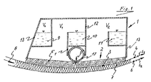
- the drainage box 1 shown in longitudinal section in FIG. 1 is closed at the bottom by a base plate 2, the lower surface 3 of which is the drainage surface and at the same time the guide surface for the upper circulating sieve 4.
- a plurality of passage channels 5 are provided for the drainage of the drainage water.
- a wire 4 can be seen at a certain distance below an upper circulating screen 4, a water-containing paper fleece 7 to be dewatered being shown between the two screens 4 and 6.
- the guidance of the two screens 4 and 6 in front of and behind the drainage box 1 is the usual type and is therefore not shown.
- the running direction of the paper fleece 7 and the two screens 4 and 6 is indicated by an arrow 8.
- the basin 9 is intended for the water which is immediately in front of the drainage box 1 for removal; the associated supply of this drainage water into the basin 9 is of a conventional type and is not shown.
- the basin 10 serves to receive the drainage water, which is in front of a wall 12 transverse to the inside of the drainage box 1 for removal, while the basin 11 is intended for the drainage water behind the transverse wall 12.
- the base plate 2 is fastened to the end walls 13 of the drainage box which are transverse in the running direction 8 of the wire 4.
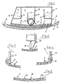
- This attachment can be of virtually any type, for example articulated, as shown schematically in FIG. 1, or rigid, as can be seen from FIG. 3. 4, where the free end of the end wall 13 and the associated end of the base plate 2 are jointly designed as a hinge joint 14.
- a rigid connection between the end wall 13 and the base plate 2 in particular a design of the associated end of the base plate 2 according to FIG. 3 is also possible, where the portion 15 of the base plate 2 located immediately behind the fastening area of the base plate 2 is considerably reduced in wall thickness in order to be there to be able to achieve a pivoting mobility under deformation.
- the base plate 2 can be formed in one part or in several parts.
- a one-part design can be seen from FIG. 2, while FIGS. 1 and 5 show a two-part design, a joint then having to be provided between the two parts 2a and 2b, as indicated schematically in FIG. 1.
- a special embodiment of such a joint 16 can be seen from FIG. 5; it is in turn a hinge joint similar to the design of the hinge joint 14 between end wall 13 and base plate 2 according to FIG. 4.
- a hose element 17 is provided in the embodiment of FIG the drainage box 1 is in rigid connection.
- the pressure inside the hose element 17 the latter widens and thereby presses on the base plate 2 from above, whereby it deflects downward and experiences the desired deflection.
- a piston / cylinder unit 18 can be used, for example according to FIG. 2.
- the transverse wall 12 which divides the interior of the drainage box 1 into a front and a rear section, to which the collecting basins 10 and 11 are assigned, must be guided over the entire height of the interior of the drainage box 1.
- the transverse wall 12 can already end at a certain distance from the top of the base plate 2, since the tube element 17, according to FIG. 1, also at the same time supports transverse wall 12 and an opposite, downward extension 19, so that the tube element 17 forms part of the transverse wall 12 in terms of effectiveness.
- the transverse wall must be extendable in itself because of the deflection of the base plate 2 under the action of the pressure element 17 or 18. This can be achieved for example by a telescopic design or the provision of a bellows element.
Landscapes
- Paper (AREA)
Claims (11)
- Unité d'égouttage pour machines à papier à table plate dites machines Fourdrinier pour procéder à l'égouttage vers le haut d'une nappe de papier contenant de l'eau qui est acheminée sur une section de toile sensiblement horizontale de l'unité d'égouttage et, de là, à nouveau acheminée sur une autre section de toile sensiblement horizontale comprenant une toile rotative supérieure guidée par des cylindres de guidage, la nappe de papier étant acheminée entre les deux sections de toile conjointement de manière qu'une section de toile moyenne passe sur une surface d'égouttage tournée vers le bas d'une caisse d'égouttage agencée à l'intérieur de la toile rotative supérieure en s'appuyant sur cette surface qui est bombée vers le bas dans le sens machine de la toile, l'unité d'égouttage étant caractérisée en ce que la plaque de base (2) de la caisse d'égouttage (1) qui forme la surface d'égouttage (3) peut être fléchie de manière variable pour modifier le bombement dirigé vers le bas de sa surface d'égouttage (3) et en ce qu'on agence dans la partie supérieure de la plaque de base (2) de la caisse d'égouttage (1) au moins un élément de compression (17, 18) à l'aide duquel la plaque de base (2) peut être fléchie de manière variable et qui, par ailleurs, s'appuie sur une partie rigide et fixe de la caisse d'égouttage (1).
- Unité d'égouttage selon la revendication 1, caractérisée en ce que l'élément de compression est constitué d'une unité à cylindre et piston pneumatique ou hydraulique (18).
- Unité d'égouttage selon la revendication 1, caractérisée en ce que l'élément de compression est constitué d'un tuyau flexible qui est placé sous pression interne hydraulique ou pneumatique et dont le diamètre peut s'agrandir en augmentant la pression qui y est admise.
- Unité d'égouttage selon au moins l'une des revendications précédentes, caractérisée en ce que la plaque de base (2) de la caisse d'égouttage (1) est agencée de manière à pouvoir pivoter sur les deux parois d'extrémité (13) de la caisse d'égouttage (1) qui sont transversales vis-à-vis du sens machine (8) de la toile (6).
- Unité d'égouttage selon la revendication 5, caractérisée en ce que, pour monter à pivotement la plaque de base (2) de la caisse d'égouttage (1) sur ses parois d'extrémité (13), il est prévu une articulation à charnière (14) entre la plaque de base (2) et la paroi d'extrémité (13).
- Unité d'égouttage selon la revendication 6, caractérisée en ce que, pour monter à pivotement la plaque de base (2) sur les parois d'extrémité (13) de la caisse d'égouttage (1), la plaque de base (2) est agencée de manière rigide sur les parois d'extrémité (13), mais présente dans la zone de montage (15) une épaisseur de paroi telle qu'elle permette un certain pivotement par déformation.
- Unité d'égouttage selon au moins l'une des revendications précédentes, caractérisée en ce que la plaque de base (2) est conformée d'un seul tenant et est constituée de matière plastique.
- Unité d'égouttage selon au moins l'une des revendications précédentes, caractérisée en ce que la plaque de base est divisée dans la zone de montage d'au moins un élément de compression (17, 18) transversalement au sens machine (8) de la toile (6) de telle sorte qu'une articulation à charnière (16) soit agencée entre les deux parties (2a, 2b).
- Unité d'égouttage selon au moins l'une des revendications précédentes, caractérisée en ce que, dans la zone de montage d'au moins un élément de compression (17, 18), une paroi (12) transversale vis-à-vis du sens machine de la toile (6) fait saillie de la plaque de base (2) vers le haut, sur laquelle paroi est agencé un collecteur (10) pour recueillir l'eau qui passe à travers la plaque de base (2) devant la paroi (12) dans le sens machine (8) de la toile (6).
- Unité d'égouttage selon la revendication 9, caractérisée en ce que la paroi transversale (12) est conformée de manière à pouvoir modifier sa longueur dans le sens de la hauteur.
- Unité d'égouttage selon la revendication 9, caractérisée en ce que la partie inférieure de la paroi transversale (12) est formée par le tuyau flexible (17) qui joue le rôle d'élément de compression.
Priority Applications (4)
| Application Number | Priority Date | Filing Date | Title |
|---|---|---|---|
| EP88109705A EP0346519B1 (fr) | 1988-06-16 | 1988-06-16 | Unité d'essorage pour machines Fourdrinier |
| AT88109705T ATE66979T1 (de) | 1988-06-16 | 1988-06-16 | Entwaesserungseinheit fuer langsiebpapiermaschinen. |
| ES198888109705T ES2025734T3 (es) | 1988-06-16 | 1988-06-16 | Unidad de drenaje de agua para maquina de hacer papel de criba longitudinal. |
| DE8888109705T DE3864683D1 (de) | 1988-06-16 | 1988-06-16 | Entwaesserungseinheit fuer langsieb-papiermaschinen. |
Applications Claiming Priority (1)
| Application Number | Priority Date | Filing Date | Title |
|---|---|---|---|
| EP88109705A EP0346519B1 (fr) | 1988-06-16 | 1988-06-16 | Unité d'essorage pour machines Fourdrinier |
Publications (2)
| Publication Number | Publication Date |
|---|---|
| EP0346519A1 EP0346519A1 (fr) | 1989-12-20 |
| EP0346519B1 true EP0346519B1 (fr) | 1991-09-04 |
Family
ID=8199066
Family Applications (1)
| Application Number | Title | Priority Date | Filing Date |
|---|---|---|---|
| EP88109705A Expired - Lifetime EP0346519B1 (fr) | 1988-06-16 | 1988-06-16 | Unité d'essorage pour machines Fourdrinier |
Country Status (4)
| Country | Link |
|---|---|
| EP (1) | EP0346519B1 (fr) |
| AT (1) | ATE66979T1 (fr) |
| DE (1) | DE3864683D1 (fr) |
| ES (1) | ES2025734T3 (fr) |
Families Citing this family (1)
| Publication number | Priority date | Publication date | Assignee | Title |
|---|---|---|---|---|
| FI98540C (fi) * | 1989-05-08 | 1997-07-10 | Valmet Corp | Laite paperi- tai kartonkirainan muodostamiseksi kuitumateriaalista |
Family Cites Families (6)
| Publication number | Priority date | Publication date | Assignee | Title |
|---|---|---|---|---|
| DE279570C (fr) * | ||||
| GB883983A (en) * | 1960-06-09 | 1961-12-06 | Lodding Engineering Corp | Adjustable supports for fourdrinier screen wires |
| US3595744A (en) * | 1965-12-22 | 1971-07-27 | Helge Natanael Skoldkvist | Pulp-forming machine |
| GB2003952A (en) * | 1977-09-06 | 1979-03-21 | Beloit Walmsley Ltd | Improvements relating to forming machines for paper webs |
| DE3138133C2 (de) * | 1981-09-04 | 1986-03-06 | Sulzer-Escher Wyss GmbH, 7980 Ravensburg | Entwässerungseinheit für Langsieb-Papiermaschinen |
| GB8307437D0 (en) * | 1983-03-17 | 1983-04-27 | Beloit Walmsley Ltd | Apparatus for dewatering fibrous suspensions on paper forming machine |
-
1988
- 1988-06-16 EP EP88109705A patent/EP0346519B1/fr not_active Expired - Lifetime
- 1988-06-16 ES ES198888109705T patent/ES2025734T3/es not_active Expired - Lifetime
- 1988-06-16 DE DE8888109705T patent/DE3864683D1/de not_active Expired - Fee Related
- 1988-06-16 AT AT88109705T patent/ATE66979T1/de active
Also Published As
| Publication number | Publication date |
|---|---|
| EP0346519A1 (fr) | 1989-12-20 |
| ATE66979T1 (de) | 1991-09-15 |
| DE3864683D1 (de) | 1991-10-10 |
| ES2025734T3 (es) | 1992-04-01 |
Similar Documents
| Publication | Publication Date | Title |
|---|---|---|
| AT398318B (de) | Leiste zur nachgiebigen stützung eines siebbandes | |
| EP0503249B1 (fr) | Dispositif d'égouttage pour la partie humide d'une machine à papier | |
| DE3138133C2 (de) | Entwässerungseinheit für Langsieb-Papiermaschinen | |
| AT406694B (de) | Verfahren zur entwässerung endloser faserstoffbahnen sowie siebpartie einer maschine zur herstellung von faserstoffbahnen | |
| EP0571585A1 (fr) | Machine a papier a deux toiles. | |
| DE3300612A1 (de) | Beschichtungsvorrichtung mit rakel, insbesondere zur beschichtung von papierbahnen | |
| CH676257A5 (fr) | ||
| DE69623150T2 (de) | Leiste für eine Entwässerungsvorrichtung in einer Papiermaschine | |
| EP0069925B1 (fr) | Partie humide d'une machine à papier | |
| CH666300A5 (de) | Vorrichtung zum fuehren der siebe einer doppelsiebpartie einer papier- oder kartonmaschine. | |
| EP0346519B1 (fr) | Unité d'essorage pour machines Fourdrinier | |
| DE1147470B (de) | Vorrichtung zum Herstellen von Bahnen aus Papier, Pappe od. dgl. | |
| DE3406217C1 (de) | Vorrichtung zum Führen der Siebe einer Doppelsiebpartie einer Papier- oder Kartonmaschine | |
| EP0254819A1 (fr) | Elément de support hydraulique pour presse | |
| DE4029965A1 (de) | Doppelsiebbandpresse | |
| DE3725527C2 (de) | Druckeinrichtung für Filterpressen | |
| DE3823966C2 (de) | Vorrichtung zum Führen der Siebe einer Doppelsiebpartie einer Papier- oder Kartonmaschine | |
| DE4028126A1 (de) | Schlitzduese, insbesondere fuer einen doppelsiebformer | |
| EP1960593B1 (fr) | Languette d'appui deformable pour un tamis et une partie de tamis double | |
| DE8807850U1 (de) | Entwässerungseinheit für Langsieb-Papiermaschinen | |
| AT399355B (de) | Vorrichtung zur entwässerung von faserstoff-flüssigkeit-mischungen | |
| DE69508136T2 (de) | Vorrichtung für die zonenweise Einstellung der Belastung in der Nasspartie einer Papier- oder Pappemaschine | |
| DE3546629C2 (en) | Device for guiding the wires of a twin-wire section of a paper- or cardboard-machine | |
| DE69712337T2 (de) | Satz von rippen in einer entwässerungsvorrichtung für eine papiermaschine | |
| DE2210862C3 (de) | Siebpartie einer nach dem Naßverfahren arbeitenden Vlieslegemaschine, insbesondere einer Papiermaschine |
Legal Events
| Date | Code | Title | Description |
|---|---|---|---|
| PUAI | Public reference made under article 153(3) epc to a published international application that has entered the european phase |
Free format text: ORIGINAL CODE: 0009012 |
|
| 17P | Request for examination filed |
Effective date: 19890721 |
|
| AK | Designated contracting states |
Kind code of ref document: A1 Designated state(s): AT BE CH DE ES FR IT LI NL |
|
| 17Q | First examination report despatched |
Effective date: 19900323 |
|
| ITF | It: translation for a ep patent filed | ||
| GRAA | (expected) grant |
Free format text: ORIGINAL CODE: 0009210 |
|
| AK | Designated contracting states |
Kind code of ref document: B1 Designated state(s): AT BE CH DE ES FR IT LI NL |
|
| REF | Corresponds to: |
Ref document number: 66979 Country of ref document: AT Date of ref document: 19910915 Kind code of ref document: T |
|
| REF | Corresponds to: |
Ref document number: 3864683 Country of ref document: DE Date of ref document: 19911010 |
|
| ET | Fr: translation filed | ||
| REG | Reference to a national code |
Ref country code: ES Ref legal event code: FG2A Ref document number: 2025734 Country of ref document: ES Kind code of ref document: T3 |
|
| PG25 | Lapsed in a contracting state [announced via postgrant information from national office to epo] |
Ref country code: AT Effective date: 19920616 |
|
| PG25 | Lapsed in a contracting state [announced via postgrant information from national office to epo] |
Ref country code: ES Free format text: LAPSE BECAUSE OF THE APPLICANT RENOUNCES Effective date: 19920617 |
|
| PG25 | Lapsed in a contracting state [announced via postgrant information from national office to epo] |
Ref country code: LI Effective date: 19920630 Ref country code: CH Effective date: 19920630 Ref country code: BE Effective date: 19920630 |
|
| PLBE | No opposition filed within time limit |
Free format text: ORIGINAL CODE: 0009261 |
|
| 26N | No opposition filed | ||
| BERE | Be: lapsed |
Owner name: GUSTAV REINHARD G.M.B.H. & CO. K.G. Effective date: 19920630 |
|
| PG25 | Lapsed in a contracting state [announced via postgrant information from national office to epo] |
Ref country code: NL Effective date: 19930101 |
|
| NLV4 | Nl: lapsed or anulled due to non-payment of the annual fee | ||
| PG25 | Lapsed in a contracting state [announced via postgrant information from national office to epo] |
Ref country code: FR Effective date: 19930226 |
|
| REG | Reference to a national code |
Ref country code: CH Ref legal event code: PL |
|
| PG25 | Lapsed in a contracting state [announced via postgrant information from national office to epo] |
Ref country code: DE Effective date: 19930302 |
|
| REG | Reference to a national code |
Ref country code: FR Ref legal event code: ST |
|
| REG | Reference to a national code |
Ref country code: ES Ref legal event code: FD2A Effective date: 19991102 |
|
| PG25 | Lapsed in a contracting state [announced via postgrant information from national office to epo] |
Ref country code: IT Free format text: LAPSE BECAUSE OF NON-PAYMENT OF DUE FEES;WARNING: LAPSES OF ITALIAN PATENTS WITH EFFECTIVE DATE BEFORE 2007 MAY HAVE OCCURRED AT ANY TIME BEFORE 2007. THE CORRECT EFFECTIVE DATE MAY BE DIFFERENT FROM THE ONE RECORDED. Effective date: 20050616 |