EP0345520B1 - Vorrichtung zum Reinigen von Abgasen, insbesondere Rauchgasen, mittels Schüttgut. - Google Patents
Vorrichtung zum Reinigen von Abgasen, insbesondere Rauchgasen, mittels Schüttgut. Download PDFInfo
- Publication number
- EP0345520B1 EP0345520B1 EP89109176A EP89109176A EP0345520B1 EP 0345520 B1 EP0345520 B1 EP 0345520B1 EP 89109176 A EP89109176 A EP 89109176A EP 89109176 A EP89109176 A EP 89109176A EP 0345520 B1 EP0345520 B1 EP 0345520B1
- Authority
- EP
- European Patent Office
- Prior art keywords
- gas
- bulk material
- layer
- plates
- permeable
- Prior art date
- Legal status (The legal status is an assumption and is not a legal conclusion. Google has not performed a legal analysis and makes no representation as to the accuracy of the status listed.)
- Expired - Lifetime
Links
- 239000007789 gas Substances 0.000 title claims abstract description 17
- 239000013590 bulk material Substances 0.000 title abstract description 18
- 238000004140 cleaning Methods 0.000 title abstract description 3
- 239000000779 smoke Substances 0.000 title 1
- 210000002816 gill Anatomy 0.000 claims abstract description 26
- 239000002245 particle Substances 0.000 claims abstract description 16
- 239000003546 flue gas Substances 0.000 claims abstract description 4
- 230000005484 gravity Effects 0.000 claims description 2
- 239000000463 material Substances 0.000 claims 4
- 239000002912 waste gas Substances 0.000 claims 2
- 238000000746 purification Methods 0.000 claims 1
- 239000002184 metal Substances 0.000 abstract 3
- 239000000571 coke Substances 0.000 abstract 1
- 238000000034 method Methods 0.000 abstract 1
- 238000001556 precipitation Methods 0.000 abstract 1
- 239000012716 precipitator Substances 0.000 abstract 1
- 239000010419 fine particle Substances 0.000 description 2
- 230000000694 effects Effects 0.000 description 1
- 230000000717 retained effect Effects 0.000 description 1
- 238000000926 separation method Methods 0.000 description 1
- 239000007787 solid Substances 0.000 description 1
- 230000003068 static effect Effects 0.000 description 1
Images
Classifications
-
- B—PERFORMING OPERATIONS; TRANSPORTING
- B01—PHYSICAL OR CHEMICAL PROCESSES OR APPARATUS IN GENERAL
- B01D—SEPARATION
- B01D45/00—Separating dispersed particles from gases or vapours by gravity, inertia, or centrifugal forces
- B01D45/04—Separating dispersed particles from gases or vapours by gravity, inertia, or centrifugal forces by utilising inertia
- B01D45/08—Separating dispersed particles from gases or vapours by gravity, inertia, or centrifugal forces by utilising inertia by impingement against baffle separators
-
- B—PERFORMING OPERATIONS; TRANSPORTING
- B01—PHYSICAL OR CHEMICAL PROCESSES OR APPARATUS IN GENERAL
- B01D—SEPARATION
- B01D46/00—Filters or filtering processes specially modified for separating dispersed particles from gases or vapours
- B01D46/30—Particle separators, e.g. dust precipitators, using loose filtering material
- B01D46/32—Particle separators, e.g. dust precipitators, using loose filtering material the material moving during filtering
- B01D46/34—Particle separators, e.g. dust precipitators, using loose filtering material the material moving during filtering not horizontally, e.g. using shoots
-
- B—PERFORMING OPERATIONS; TRANSPORTING
- B01—PHYSICAL OR CHEMICAL PROCESSES OR APPARATUS IN GENERAL
- B01D—SEPARATION
- B01D53/00—Separation of gases or vapours; Recovering vapours of volatile solvents from gases; Chemical or biological purification of waste gases, e.g. engine exhaust gases, smoke, fumes, flue gases, aerosols
- B01D53/02—Separation of gases or vapours; Recovering vapours of volatile solvents from gases; Chemical or biological purification of waste gases, e.g. engine exhaust gases, smoke, fumes, flue gases, aerosols by adsorption, e.g. preparative gas chromatography
- B01D53/06—Separation of gases or vapours; Recovering vapours of volatile solvents from gases; Chemical or biological purification of waste gases, e.g. engine exhaust gases, smoke, fumes, flue gases, aerosols by adsorption, e.g. preparative gas chromatography with moving adsorbents, e.g. rotating beds
- B01D53/08—Separation of gases or vapours; Recovering vapours of volatile solvents from gases; Chemical or biological purification of waste gases, e.g. engine exhaust gases, smoke, fumes, flue gases, aerosols by adsorption, e.g. preparative gas chromatography with moving adsorbents, e.g. rotating beds according to the "moving bed" method
-
- B—PERFORMING OPERATIONS; TRANSPORTING
- B01—PHYSICAL OR CHEMICAL PROCESSES OR APPARATUS IN GENERAL
- B01D—SEPARATION
- B01D53/00—Separation of gases or vapours; Recovering vapours of volatile solvents from gases; Chemical or biological purification of waste gases, e.g. engine exhaust gases, smoke, fumes, flue gases, aerosols
- B01D53/34—Chemical or biological purification of waste gases
-
- B—PERFORMING OPERATIONS; TRANSPORTING
- B01—PHYSICAL OR CHEMICAL PROCESSES OR APPARATUS IN GENERAL
- B01D—SEPARATION
- B01D2253/00—Adsorbents used in seperation treatment of gases and vapours
- B01D2253/10—Inorganic adsorbents
- B01D2253/102—Carbon
-
- B—PERFORMING OPERATIONS; TRANSPORTING
- B01—PHYSICAL OR CHEMICAL PROCESSES OR APPARATUS IN GENERAL
- B01D—SEPARATION
- B01D2253/00—Adsorbents used in seperation treatment of gases and vapours
- B01D2253/30—Physical properties of adsorbents
- B01D2253/302—Dimensions
- B01D2253/304—Linear dimensions, e.g. particle shape, diameter
-
- B—PERFORMING OPERATIONS; TRANSPORTING
- B01—PHYSICAL OR CHEMICAL PROCESSES OR APPARATUS IN GENERAL
- B01D—SEPARATION
- B01D2258/00—Sources of waste gases
- B01D2258/02—Other waste gases
- B01D2258/0283—Flue gases
Definitions
- the invention relates to a device for cleaning exhaust gases, in particular flue gases, by means of bulk material, which by gravity travels through a shaft which is arranged essentially vertically and is delimited on opposite sides by gas-permeable walls and is essentially crossed by a horizontally oriented exhaust gas flow, with a device for Continuous discharge of particles that have passed through the gas-permeable wall on the outflow side downwards and one arranged on the outflow side of the bulk material layer at a distance from the gas-permeable wall and a baffle separator arrangement that covers the surface of the gas-permeable wall and consists of a large number of blinds that are inclined from the outside inwards arranged and horizontally extending baffle plates.
- the gas-permeable wall on the outflow side is designed as a blind, wire mesh, perforated plate or porous plate. With such permeable walls, there is a risk of being too high Pressure loss such. B. when using a blind or a blockage as in the case of a perforated plate, if the bulk material itself is finely divided or fine particles arise when walking through the bulk layer and if at the same time the thickness of the perforated plate is greater than the cross section of the holes. The hole diameter in the perforated plate is determined by the smallest diameter of the bulk material to be held, while the thickness of the perforated plate is determined by the static load from the layer of bulk material.
- the efficiency of the impact separator arrangement in the known device is not sufficient in all cases, since the impact of the particles emerging from the gas-permeable wall on the downstream side on the impact plates of the impact separator arrangement does not always occur in the direction downward onto the discharge channel between the downstream gas-permeable wall and the impact separator arrangement. Because of the flow of the partial gas flows emerging from the outflow-side blind into the space between the baffle plates, a substantial part of the solids, in particular all fine particles, will be guided parallel to the baffle plates and a substantial part will enter the clean gas flow via the outer edge of the baffle plates.
- the gas-permeable wall on the outflow side is designed as a gill plate provided with gills bent into the bulk material layer or away from the bulk material layer, and on the in the flow direction of the Gas flow outside edges of the baffle plates are provided.
- the gills can be bent downwards and into the bulk layer and upwards and away from the bulk layer.
- the distance between the free edge of the bent gill and the plane of the plate determines the effective hole cross section.
- the individual particle is in engagement with the plate over the entire thickness of the plate, so that there is a risk of clogging is significantly increased.
- the particles captured by the baffle plate are passed onto the baffle plates of the baffle separator arrangement and are led away downwards from them, so that they can slide downward, preferably agglomerated, over the lower edge of the baffle plates.
- Particles are deliberately let through the gill plate to prevent the openings from becoming blocked.
- the angle of attack of the baffle plates with respect to the horizontal is preferably in the range from 30 to below 90 °.
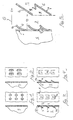
- FIG. 1 and 2 need no further explanation.
- the gill plate 1 according to FIG. 3 has a multiplicity of holes 2, each of which is assigned a gill 3 which is bent downwards and into the bulk material layer S.
- the effective cross section of the hole 2 is determined by the distance of the free edge 3a of the gill from the plane of the gill plate 1.
- each hole 2 a gill 4 bent upwards and away from the bulk material layer.
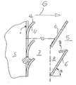
- FIG. 5 When in the FIG. 5 shown as a partial cross section
- the bulk material layer S is delimited by a gill plate 1 with gills 4 bent upwards.
- FIG. 5 is shown schematically, larger particles than the effective cross section are retained on the free edge 4a of the gill 4, while smaller particles are discharged with the gas stream G passing through the gill plate.
- These particles are separated on the impact separator 5 which is arranged at a distance from the gill plate 1 and are drawn downwards by the gravitational force acting on them in accordance with the dash-dotted line.
- the impact separator 5 consists of a plurality of impact plates 6 arranged one above the other and inclined from the outside inward, the angle of attack ⁇ of which lies in the range from 30 ° to 90 ° to the horizontal.
- the particles which are separated from the impact separator 5 and fed to the discharge space 7 are at the lower end of the discharge space 7 by means not shown, such as eg discharge screws or the like, removed or collected in a collection volume provided below the discharge space 7.
- particles entrained from the layer S do not accumulate in the pockets 8 between the impact separator plates 6.
- the impact separator plates 6 are at their upper outer edges in the from FIG. 2 evident way be provided with catch plates 9, which can of course also be formed integrally with the baffle plates.
Landscapes
- Chemical & Material Sciences (AREA)
- Chemical Kinetics & Catalysis (AREA)
- Engineering & Computer Science (AREA)
- General Chemical & Material Sciences (AREA)
- Oil, Petroleum & Natural Gas (AREA)
- Analytical Chemistry (AREA)
- Environmental & Geological Engineering (AREA)
- Health & Medical Sciences (AREA)
- Biomedical Technology (AREA)
- Separating Particles In Gases By Inertia (AREA)
- Filtering Of Dispersed Particles In Gases (AREA)
- Exhaust Gas After Treatment (AREA)
- Devices And Processes Conducted In The Presence Of Fluids And Solid Particles (AREA)
Description
- Die Erfindung betrifft eine Vorrichtung zum Reinigen von Abgasen, insbesondere von Rauchgasen, mittels Schüttgut, das mittels Schwerkraft einen im wesentlichen vertikal angeordneten und auf gegenüberliegenden Seiten von gasdurchlässigen Wänden begrenzten Schacht durchwandert und im wesentlichen von einem horizontal ausgerichteten Abgasstrom durchkreuzt wird, mit einer Einrichtung zum fortlaufenden Abführen von durch die gasdurchlässige Wand auf der Abströmseite durchgetretenen Partikeln nach unten und einer auf der Abströmseite der Schüttgutschicht mit Abstand von der gasdurchlässigen Wand angeordneten und eine die Fläche der gasdurchlässigen Wand abdeckenden Prallabscheideranordnung bestehend aus einer Vielzahl von von außen nach innen geneigten, jalousieartig übereinander angeordneten und sich horizontal erstreckenden Prallplatten.
- Eine solche Vorrichtung ist aus Patent Abstracts of Japan, Band 8, Nr. 77 (C-218)[1514], 10. April 1984; & JP-A-59 329 (Babcock Hitachi K.K) 05-01-1984 bekannt. Bei der dort gezeigten Vorrichtung ist die gasdurchlässige Wand auf der Abströmseite als Jalousie, Drahtnetz, Lochplatte oder poröse Platte ausgebildet. Bei derartig ausgebildeten durchlässigen Wänden besteht die Gefahr eines zu hohen Druckverlustes wie z. B. bei dem Einsatz einer Jalousie oder einer Verstopfung wie im Falle eines Lochbleches, wenn das Schüttgut selbst feinteilig ist oder beim Durchwandern der Schüttgutschicht Feinteile entstehen und wenn zugleich die Dicke des Lochbleches größer ist als der Querschnitt der Löcher. Der Lochdurchmesser im Lochblech wird dabei durch den kleinsten Durchmesser des zu haltenden Schüttguts bestimmt, während die Dicke des Lochbleches durch die statische Belastung durch die Schüttgutschicht bestimmt ist.
- Der Wirkungsgrad der Prallabscheideranordnung bei der bekannten Vorrichtung ist nicht in allen Fällen ausreichend, da der Abprall der aus der gasdurchlässigen Wand auf der Abströmseite austretenden Teilchen an den Prallplatten der Prallabscheideranordnung nicht immer in Richtung nach unten auf den Abzugskanal zwischen abströmseitiger gasdurchlässiger Wand und Prallabscheideranordnung erfolgt. Wegen der Strömungsführung der aus der abströmseitigen Jalousie austretenden Gasteilströme in den Zwischenraum zwischen den Prallplatten wird ein wesentlicher Teil der Feststoffe, insbesondere alle Feinanteile, parallel zu den Prallplatten geführt werden und ein wesentlicher Teil über die Außenkante der Prallplatten in den Reingasstrom eintreten.
- Es ist daher die Aufgabe der vorliegenden Erfindung, eine Vorrichtung der gattungsgemäßen Art anzugeben, bei der einerseits die Verstopfungsgefahr vermindert und andererseits die Abscheidewirkung der Prallabscheideranordnung verbessert wird.
- Diese Aufgabe wird dadurch gelöst, daß die gasdurchlässige Wand auf der Abströmseite als ein mit in die Schüttgutschicht hinein- oder von der Schüttgutschicht fort ausgebogenen Kiemen versehenes Kiemenblech ausgebildet ist und an den in Strömungsrichtung des Gasstroms außen liegenden Kanten der Prallplatten Fangbleche vorgesehen sind.
- Bei dem Kiemenblech können die Kiemen nach unten und in die Schüttgutschicht hinein und nach oben und von der Schüttgutschicht fort ausgebogen sein. Bei den Kiemenblechen bestimmt der Abstand der freien Kante der ausgebogenen Kieme von der Ebene des Bleches den effektiven Lochquerschnitt. Bei Kiemenblechen kommt es zwischen dem an die Öffnung herangeführten Teilchen und dem Blech im wesentlichen nur zu einem Linieneingriff, während bei den normalen als Flachblech ausgebildeten Lochblechen das einzelne Partikel über die gesamte Dicke des Bleches im Eingriff mit dem Blech steht, so daß dort die Verstopfungsgefahr deutlich erhöht wird.
- Die vom Fangblech eingefangenen Partikeln werden auf die Prallplatten der Prallabscheideranordnung geleitet und von diesen nach unten abgeführt, so daß sie vorzugsweise agglomeriert über die untere Kante der Prallplatten nach unten abrutschen können.
- Durch das Kiemenblech werden bewußt Partikel durchgelassen, um ein Verstopfen der Öffnungen zu verhindern. Durch die Zuordnung von Fangblechen zu den einzelnen Prallplatten der Prallabscheideranordnung werden auch bewußt durchgelassene kleinere Partikel im wesentlichen sicher abgeschieden.
- Der Anstellwinkel der Prallplatten gegenüber der Horizontalen liegt vorzugsweise im Bereich von 30 bis unter 90°.
- Die Erfindung soll nun anhand der beigefügten Figuren näher erläutert werden. Es zeigen:
- FIG. 1
- eine Aufsicht auf und einen Schnitt durch ein bekanntes Lochblech mit kreisrunden Löchern,
- FIG. 2
- eine Darstellung vergleichbar FIG. 1 für ein bekanntes Schlitzblech,
- FIG. 3
- eine Darstellung vergleichbar FIG. 1 für ein erfindungsgemäßes Kiemenblech mit nach unten ausgebogenen Kiemen,
- FIG. 4
- eine Darstellung vergleichbar FIG. 3 mit nach oben und außen ausgebogenen Kiemen und
- FIG. 5
- einen Teilschnitt durch ein Kiemenblech auf der Abströmseite der Schüttgutschicht und einen nachgeschalteten Prallabscheider mit übereinander angeordneten Prallplatten.
- Die FIG. 1 und 2 bedürfen keiner näheren Erläuterung.
- Das Kiemenblech 1 gemäß FIG. 3 weist eine Vielzahl von Löchern 2 auf, denen jeweils eine nach unten und in die Schüttgutschicht S hinein ausgebogene Kieme 3 zugeordnet ist. Der effektive Querschnitt des Loches 2 ist durch den Abstand der freien Kante 3a der Kieme von der Ebene des Kiemenbleches 1 bestimmt.
- Bei der FIG. 4 ist jedem Loch 2 eine nach oben und von der Schüttgutschicht fort gebogene Kieme 4 zugeordnet.
- Bei der in der FIG. 5 als Teilquerschnitt dargestellten Vorrichtung wird die Schüttgutschicht S von einem Kiemenblech 1 mit nach oben ausgebogenen Kiemen 4 begrenzt. Wie in der FIG. 5 schematisch dargestellt ist, werden größere Teilchen als der effektive Querschnitt an der freien Kante 4a der Kieme 4 zurückgehalten, während kleinere Teilchen mit dem durch das Kiemenblech tretenden Gasstrom G ausgetragen werden. Diese Partikeln werden an dem mit Abstand von dem Kiemenblech 1 angeordneten Prallabscheider 5 abgeschieden und durch die auf sie wirkende Schwerkraft entsprechend der strichpunktierten Linie nach unten abgezogen. Der Prallabscheider 5 besteht aus einer Vielzahl von übereinander angeordneten und von außen nach innen geneigten Prallplatten 6, deren Anstellwinkel α gegen die Horizontale im Bereich von 30° bis 90° liegt. Um einen Aufbau einer Schüttgutschicht in dem zwischen dem Kiemenblech 1 und dem Prallabscheider 5 vorhandenen Ableitraum 7 zu vermeiden, werden die Partikeln, die von dem Prallabscheider 5 abgeschieden und dem Ableitraum 7 zugeführt werden, am unteren Ende des Ableitraumes 7 durch nicht gezeigte Einrichtungen, wie z.B. Austragsschnecken oder dergleichen, abgeführt oder in einem unterhalb des Ableitraumes 7 vorgesehenen Sammelvolumen gesammelt. Es kommt bei Betrieb der erfindungsgemäßen Vorrichtung jedenfalls nicht zu einem Ansammeln von aus der Schicht S mitgerissenen Teilchen in den Taschen 8 zwischen den Prallabscheiderplatten 6.
- Die Prallabscheiderplatten 6 sind an ihren oberen außen liegenden Kanten in der aus der FIG. 2 ersichtlichen Weise mit Fangblechen 9 versehen sein, die selbstverständlich auch einstückig mit den Prallplatten ausgebildet ausgebildet sein können.
Claims (2)
- Vorrichtung zum Reinigen von Abgasen (G), insbesondere von Rauchgasen, mittels Schüttgut (S), das mittels Schwerkraft einen im wesentlichen vertikal angeordneten und auf gegenüberliegenden Seiten von gasdurchlässigen Wänden begrenzten Schacht durchwandert und im wesentlichen von einem horizontal ausgerichteten Abgasstrom (G) durchkreuzt wird, mit einer Einrichtung (7) zum fortlaufenden Abführen von durch die gasdurchlässige Wand (1) auf der Abströmseite durchgetretenen Partikeln nach unten und einer auf der Abströmseite der Schüttgutschicht mit Abstand von der gasdurchlässigen Wand angeordneten und eine die Fläche der gasdurchlässigen Wand (1) abdeckenden Prallabscheideranordnung (5) bestehend aus einer Vielzahl von von außen nach innen geneigten, jalousieartig übereinander angeordneten und sich horizontal erstreckenden Prallplatten (6),
dadurch gekennzeichnet,
daß die gasdurchlässige Wand auf der Abströmseite als ein mit in die Schüttgutschicht hinein- oder von der Schüttgutschicht fort ausgebogenen Kiemen versehenes Kiemenblech (1; 2, 3; 2, 4) ausgebildet ist und an den in Strömungsrichtung des Gasstromes (G) außen liegenden Kanten der Prallplatten (6) Fangbleche (9) vorgesehen sind. - Vorrichtung nach Anspruch 1,
dadurch gekennzeichnet,
daß der Anstellwinkel ( ) der Prallplatten (6) gegenüber der Horizontalen im Bereich von 30° bis unter 90° liegt.
Priority Applications (1)
| Application Number | Priority Date | Filing Date | Title |
|---|---|---|---|
| AT89109176T ATE98510T1 (de) | 1988-05-25 | 1989-05-22 | Vorrichtung zum reinigen von abgasen, insbesondere rauchgasen, mittels schuettgut. |
Applications Claiming Priority (2)
| Application Number | Priority Date | Filing Date | Title |
|---|---|---|---|
| DE3817686 | 1988-05-25 | ||
| DE3817686A DE3817686C1 (de) | 1988-05-25 | 1988-05-25 |
Publications (2)
| Publication Number | Publication Date |
|---|---|
| EP0345520A1 EP0345520A1 (de) | 1989-12-13 |
| EP0345520B1 true EP0345520B1 (de) | 1993-12-15 |
Family
ID=6355062
Family Applications (1)
| Application Number | Title | Priority Date | Filing Date |
|---|---|---|---|
| EP89109176A Expired - Lifetime EP0345520B1 (de) | 1988-05-25 | 1989-05-22 | Vorrichtung zum Reinigen von Abgasen, insbesondere Rauchgasen, mittels Schüttgut. |
Country Status (5)
| Country | Link |
|---|---|
| EP (1) | EP0345520B1 (de) |
| AT (1) | ATE98510T1 (de) |
| CZ (1) | CZ279104B6 (de) |
| DD (1) | DD283861A5 (de) |
| DE (2) | DE3817686C1 (de) |
Families Citing this family (2)
| Publication number | Priority date | Publication date | Assignee | Title |
|---|---|---|---|---|
| DE4126146C2 (de) * | 1990-10-16 | 1993-09-30 | Steag Ag | Adsorptionsmittel-, insbesondere Wanderbettreaktor |
| AT525952A1 (de) * | 2022-02-24 | 2023-09-15 | Beilschmidt Alfred | Vorrichtung zur Behandlung von Abgasen einer Kleinfeuerungsanlage |
Family Cites Families (6)
| Publication number | Priority date | Publication date | Assignee | Title |
|---|---|---|---|---|
| DE183921C (de) * | ||||
| GB926358A (en) * | 1960-07-18 | 1963-05-15 | Howden James & Co Ltd | Dust separators |
| DE2626939A1 (de) * | 1976-06-16 | 1977-12-29 | Babcock Ag | Verfahren und vorrichtung zum abtrennen von unerwuenschten gasfoermigen bestandteilen aus einem abgas |
| DE2741031C2 (de) * | 1976-09-13 | 1986-02-20 | Joy Manufacturing Co., Pittsburgh, Pa. | Senkrecht stehendes Gasfilter |
| DE3635571A1 (de) * | 1986-10-20 | 1988-04-28 | Krantz H Gmbh & Co | Vorrichtung zur aufnahme von rieselfaehigem schuettgut |
| DE8706726U1 (de) * | 1987-05-11 | 1987-07-02 | H. Krantz Gmbh & Co, 5100 Aachen | Leitvorrichtung für rieselfähiges Schüttgut |
-
1988
- 1988-05-25 DE DE3817686A patent/DE3817686C1/de not_active Expired - Lifetime
-
1989
- 1989-05-22 DE DE89109176T patent/DE58906404D1/de not_active Expired - Lifetime
- 1989-05-22 EP EP89109176A patent/EP0345520B1/de not_active Expired - Lifetime
- 1989-05-22 AT AT89109176T patent/ATE98510T1/de not_active IP Right Cessation
- 1989-05-24 DD DD89328872A patent/DD283861A5/de not_active IP Right Cessation
- 1989-05-25 CZ CS893136A patent/CZ279104B6/cs unknown
Also Published As
| Publication number | Publication date |
|---|---|
| CZ279104B6 (en) | 1994-12-15 |
| EP0345520A1 (de) | 1989-12-13 |
| DE3817686C1 (de) | 1990-01-04 |
| DE58906404D1 (de) | 1994-01-27 |
| DD283861A5 (de) | 1990-10-24 |
| ATE98510T1 (de) | 1994-01-15 |
| CS8903136A2 (en) | 1991-11-12 |
Similar Documents
| Publication | Publication Date | Title |
|---|---|---|
| EP1690588B1 (de) | Anordnung zum Abscheiden von Grobasche aus einem Rauchgasstrom | |
| EP0303034B1 (de) | Verfahren zur Müllsortierung und Müllsortiervorrichtung | |
| DE102013017868B4 (de) | Filtervorrichtung | |
| DE3626053C2 (de) | ||
| EP0301217B1 (de) | Abscheider zur Trennung von Tabak-Teilchen aus einem Tabak/Gas-Gemisch | |
| DE3209049C2 (de) | Vorrichtung zum Abtrennen von Leichtpartikeln aus festem Schüttgut | |
| EP0345520B1 (de) | Vorrichtung zum Reinigen von Abgasen, insbesondere Rauchgasen, mittels Schüttgut. | |
| DE19850320C2 (de) | Kompaktanlage für die mechanische Reinigung von Abwasser | |
| DE2433514C2 (de) | Vorrichtung zur Abscheidung von Pulvern und Stäuben | |
| DE2522097A1 (de) | Vorrichtung zum abscheiden von festen stoffen aus einem gasstrom | |
| EP0264669B1 (de) | Vorrichtung zur Aufnahme von rieselfähigem Schüttgut | |
| DE2904830C2 (de) | Vorrichtung zum Abscheiden feiner Nebeltröpfchen | |
| DE2215679B2 (de) | Abscheider für Flüssigkeitströpfchen aus einem Gasstrom | |
| EP3711840B1 (de) | Entstaubungsanlage | |
| CH637845A5 (de) | Verfahren und vorrichtung zur intermittierenden, regenerierenden reinigung eines filterbettes. | |
| EP0321914A1 (de) | Verfahren und Vorrichtung zum Abscheiden von Staub aus Heissgasen | |
| DE1224132B (de) | Vorrichtung zum Sichten von koernigem Gut in verschiedene Kornklassen | |
| DE2163735B2 (de) | Vorrichtung zum abscheiden von fluessigkeitstropfen aus einem stroemenden gasfoermigen medium | |
| DE2608721C2 (de) | Anlage zur Trennung eines Gemisches aus Schrott und Schutt | |
| DE3824728C1 (de) | ||
| DE4117001A1 (de) | Umlenksichter mit verdraengerkoerper | |
| DE8703776U1 (de) | Vorrichtung zur Wiederaufbereitung von Recyclingstoffen, vorzugsweise Bauschutt | |
| DE3427320A1 (de) | Granulatfilter | |
| DD203237A1 (de) | Vorrichtung und verfahren zum entstauben von schuettguetern, insbesondere granulaten aus synthetischen hochpolymeren | |
| DE3440145A1 (de) | Verfahren und vorrichtung zum entstauben von gas durch in schichten angeordnete granulatschuettungen |
Legal Events
| Date | Code | Title | Description |
|---|---|---|---|
| PUAI | Public reference made under article 153(3) epc to a published international application that has entered the european phase |
Free format text: ORIGINAL CODE: 0009012 |
|
| AK | Designated contracting states |
Kind code of ref document: A1 Designated state(s): AT CH DE LI NL SE |
|
| 17P | Request for examination filed |
Effective date: 19900612 |
|
| 17Q | First examination report despatched |
Effective date: 19910916 |
|
| GRAA | (expected) grant |
Free format text: ORIGINAL CODE: 0009210 |
|
| AK | Designated contracting states |
Kind code of ref document: B1 Designated state(s): AT CH DE LI NL SE |
|
| REF | Corresponds to: |
Ref document number: 98510 Country of ref document: AT Date of ref document: 19940115 Kind code of ref document: T |
|
| REF | Corresponds to: |
Ref document number: 58906404 Country of ref document: DE Date of ref document: 19940127 |
|
| RAP2 | Party data changed (patent owner data changed or rights of a patent transferred) |
Owner name: HUGO PETERSEN GES. FUER VERFAHRENSTECHN. ANLAGENBA |
|
| REG | Reference to a national code |
Ref country code: CH Ref legal event code: PUE Owner name: HUGO PETERSEN GESELLSCHAFT FUER VERFAHRENSTECHNISC |
|
| PLBE | No opposition filed within time limit |
Free format text: ORIGINAL CODE: 0009261 |
|
| STAA | Information on the status of an ep patent application or granted ep patent |
Free format text: STATUS: NO OPPOSITION FILED WITHIN TIME LIMIT |
|
| 26N | No opposition filed | ||
| EAL | Se: european patent in force in sweden |
Ref document number: 89109176.1 |
|
| PGFP | Annual fee paid to national office [announced via postgrant information from national office to epo] |
Ref country code: SE Payment date: 19971127 Year of fee payment: 9 |
|
| PGFP | Annual fee paid to national office [announced via postgrant information from national office to epo] |
Ref country code: AT Payment date: 19971128 Year of fee payment: 9 |
|
| PGFP | Annual fee paid to national office [announced via postgrant information from national office to epo] |
Ref country code: NL Payment date: 19971130 Year of fee payment: 9 |
|
| PGFP | Annual fee paid to national office [announced via postgrant information from national office to epo] |
Ref country code: CH Payment date: 19971201 Year of fee payment: 9 |
|
| PG25 | Lapsed in a contracting state [announced via postgrant information from national office to epo] |
Ref country code: AT Free format text: LAPSE BECAUSE OF NON-PAYMENT OF DUE FEES Effective date: 19980522 |
|
| PG25 | Lapsed in a contracting state [announced via postgrant information from national office to epo] |
Ref country code: SE Free format text: LAPSE BECAUSE OF NON-PAYMENT OF DUE FEES Effective date: 19980523 |
|
| PG25 | Lapsed in a contracting state [announced via postgrant information from national office to epo] |
Ref country code: LI Free format text: LAPSE BECAUSE OF NON-PAYMENT OF DUE FEES Effective date: 19980531 Ref country code: CH Free format text: LAPSE BECAUSE OF NON-PAYMENT OF DUE FEES Effective date: 19980531 |
|
| PG25 | Lapsed in a contracting state [announced via postgrant information from national office to epo] |
Ref country code: NL Free format text: LAPSE BECAUSE OF NON-PAYMENT OF DUE FEES Effective date: 19981201 |
|
| REG | Reference to a national code |
Ref country code: CH Ref legal event code: PL |
|
| EUG | Se: european patent has lapsed |
Ref document number: 89109176.1 |
|
| NLV4 | Nl: lapsed or anulled due to non-payment of the annual fee |
Effective date: 19981201 |
|
| PGFP | Annual fee paid to national office [announced via postgrant information from national office to epo] |
Ref country code: DE Payment date: 20080520 Year of fee payment: 20 |