EP0345520B1 - Dispositif pour le purification de gaz, en particulier gaz de fumée, utilisant une couche de matière en vrac. - Google Patents
Dispositif pour le purification de gaz, en particulier gaz de fumée, utilisant une couche de matière en vrac. Download PDFInfo
- Publication number
- EP0345520B1 EP0345520B1 EP89109176A EP89109176A EP0345520B1 EP 0345520 B1 EP0345520 B1 EP 0345520B1 EP 89109176 A EP89109176 A EP 89109176A EP 89109176 A EP89109176 A EP 89109176A EP 0345520 B1 EP0345520 B1 EP 0345520B1
- Authority
- EP
- European Patent Office
- Prior art keywords
- gas
- bulk material
- layer
- plates
- permeable
- Prior art date
- Legal status (The legal status is an assumption and is not a legal conclusion. Google has not performed a legal analysis and makes no representation as to the accuracy of the status listed.)
- Expired - Lifetime
Links
Images
Classifications
-
- B—PERFORMING OPERATIONS; TRANSPORTING
- B01—PHYSICAL OR CHEMICAL PROCESSES OR APPARATUS IN GENERAL
- B01D—SEPARATION
- B01D45/00—Separating dispersed particles from gases or vapours by gravity, inertia, or centrifugal forces
- B01D45/04—Separating dispersed particles from gases or vapours by gravity, inertia, or centrifugal forces by utilising inertia
- B01D45/08—Separating dispersed particles from gases or vapours by gravity, inertia, or centrifugal forces by utilising inertia by impingement against baffle separators
-
- B—PERFORMING OPERATIONS; TRANSPORTING
- B01—PHYSICAL OR CHEMICAL PROCESSES OR APPARATUS IN GENERAL
- B01D—SEPARATION
- B01D46/00—Filters or filtering processes specially modified for separating dispersed particles from gases or vapours
- B01D46/30—Particle separators, e.g. dust precipitators, using loose filtering material
- B01D46/32—Particle separators, e.g. dust precipitators, using loose filtering material the material moving during filtering
- B01D46/34—Particle separators, e.g. dust precipitators, using loose filtering material the material moving during filtering not horizontally, e.g. using shoots
-
- B—PERFORMING OPERATIONS; TRANSPORTING
- B01—PHYSICAL OR CHEMICAL PROCESSES OR APPARATUS IN GENERAL
- B01D—SEPARATION
- B01D53/00—Separation of gases or vapours; Recovering vapours of volatile solvents from gases; Chemical or biological purification of waste gases, e.g. engine exhaust gases, smoke, fumes, flue gases, aerosols
- B01D53/02—Separation of gases or vapours; Recovering vapours of volatile solvents from gases; Chemical or biological purification of waste gases, e.g. engine exhaust gases, smoke, fumes, flue gases, aerosols by adsorption, e.g. preparative gas chromatography
- B01D53/06—Separation of gases or vapours; Recovering vapours of volatile solvents from gases; Chemical or biological purification of waste gases, e.g. engine exhaust gases, smoke, fumes, flue gases, aerosols by adsorption, e.g. preparative gas chromatography with moving adsorbents, e.g. rotating beds
- B01D53/08—Separation of gases or vapours; Recovering vapours of volatile solvents from gases; Chemical or biological purification of waste gases, e.g. engine exhaust gases, smoke, fumes, flue gases, aerosols by adsorption, e.g. preparative gas chromatography with moving adsorbents, e.g. rotating beds according to the "moving bed" method
-
- B—PERFORMING OPERATIONS; TRANSPORTING
- B01—PHYSICAL OR CHEMICAL PROCESSES OR APPARATUS IN GENERAL
- B01D—SEPARATION
- B01D53/00—Separation of gases or vapours; Recovering vapours of volatile solvents from gases; Chemical or biological purification of waste gases, e.g. engine exhaust gases, smoke, fumes, flue gases, aerosols
- B01D53/34—Chemical or biological purification of waste gases
-
- B—PERFORMING OPERATIONS; TRANSPORTING
- B01—PHYSICAL OR CHEMICAL PROCESSES OR APPARATUS IN GENERAL
- B01D—SEPARATION
- B01D2253/00—Adsorbents used in seperation treatment of gases and vapours
- B01D2253/10—Inorganic adsorbents
- B01D2253/102—Carbon
-
- B—PERFORMING OPERATIONS; TRANSPORTING
- B01—PHYSICAL OR CHEMICAL PROCESSES OR APPARATUS IN GENERAL
- B01D—SEPARATION
- B01D2253/00—Adsorbents used in seperation treatment of gases and vapours
- B01D2253/30—Physical properties of adsorbents
- B01D2253/302—Dimensions
- B01D2253/304—Linear dimensions, e.g. particle shape, diameter
-
- B—PERFORMING OPERATIONS; TRANSPORTING
- B01—PHYSICAL OR CHEMICAL PROCESSES OR APPARATUS IN GENERAL
- B01D—SEPARATION
- B01D2258/00—Sources of waste gases
- B01D2258/02—Other waste gases
- B01D2258/0283—Flue gases
Definitions
- the invention relates to a device for cleaning exhaust gases, in particular flue gases, by means of bulk material, which by gravity travels through a shaft which is arranged essentially vertically and is delimited on opposite sides by gas-permeable walls and is essentially crossed by a horizontally oriented exhaust gas flow, with a device for Continuous discharge of particles that have passed through the gas-permeable wall on the outflow side downwards and one arranged on the outflow side of the bulk material layer at a distance from the gas-permeable wall and a baffle separator arrangement that covers the surface of the gas-permeable wall and consists of a large number of blinds that are inclined from the outside inwards arranged and horizontally extending baffle plates.
- the gas-permeable wall on the outflow side is designed as a blind, wire mesh, perforated plate or porous plate. With such permeable walls, there is a risk of being too high Pressure loss such. B. when using a blind or a blockage as in the case of a perforated plate, if the bulk material itself is finely divided or fine particles arise when walking through the bulk layer and if at the same time the thickness of the perforated plate is greater than the cross section of the holes. The hole diameter in the perforated plate is determined by the smallest diameter of the bulk material to be held, while the thickness of the perforated plate is determined by the static load from the layer of bulk material.
- the efficiency of the impact separator arrangement in the known device is not sufficient in all cases, since the impact of the particles emerging from the gas-permeable wall on the downstream side on the impact plates of the impact separator arrangement does not always occur in the direction downward onto the discharge channel between the downstream gas-permeable wall and the impact separator arrangement. Because of the flow of the partial gas flows emerging from the outflow-side blind into the space between the baffle plates, a substantial part of the solids, in particular all fine particles, will be guided parallel to the baffle plates and a substantial part will enter the clean gas flow via the outer edge of the baffle plates.
- the gas-permeable wall on the outflow side is designed as a gill plate provided with gills bent into the bulk material layer or away from the bulk material layer, and on the in the flow direction of the Gas flow outside edges of the baffle plates are provided.
- the gills can be bent downwards and into the bulk layer and upwards and away from the bulk layer.
- the distance between the free edge of the bent gill and the plane of the plate determines the effective hole cross section.
- the individual particle is in engagement with the plate over the entire thickness of the plate, so that there is a risk of clogging is significantly increased.
- the particles captured by the baffle plate are passed onto the baffle plates of the baffle separator arrangement and are led away downwards from them, so that they can slide downward, preferably agglomerated, over the lower edge of the baffle plates.
- Particles are deliberately let through the gill plate to prevent the openings from becoming blocked.
- the angle of attack of the baffle plates with respect to the horizontal is preferably in the range from 30 to below 90 °.
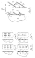
- FIG. 1 and 2 need no further explanation.
- the gill plate 1 according to FIG. 3 has a multiplicity of holes 2, each of which is assigned a gill 3 which is bent downwards and into the bulk material layer S.
- the effective cross section of the hole 2 is determined by the distance of the free edge 3a of the gill from the plane of the gill plate 1.
- each hole 2 a gill 4 bent upwards and away from the bulk material layer.
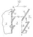
- FIG. 5 When in the FIG. 5 shown as a partial cross section
- the bulk material layer S is delimited by a gill plate 1 with gills 4 bent upwards.
- FIG. 5 is shown schematically, larger particles than the effective cross section are retained on the free edge 4a of the gill 4, while smaller particles are discharged with the gas stream G passing through the gill plate.
- These particles are separated on the impact separator 5 which is arranged at a distance from the gill plate 1 and are drawn downwards by the gravitational force acting on them in accordance with the dash-dotted line.
- the impact separator 5 consists of a plurality of impact plates 6 arranged one above the other and inclined from the outside inward, the angle of attack ⁇ of which lies in the range from 30 ° to 90 ° to the horizontal.
- the particles which are separated from the impact separator 5 and fed to the discharge space 7 are at the lower end of the discharge space 7 by means not shown, such as eg discharge screws or the like, removed or collected in a collection volume provided below the discharge space 7.
- particles entrained from the layer S do not accumulate in the pockets 8 between the impact separator plates 6.
- the impact separator plates 6 are at their upper outer edges in the from FIG. 2 evident way be provided with catch plates 9, which can of course also be formed integrally with the baffle plates.
Claims (2)
- Appareil d'épuration de gaz rejetés (G), notamment de fumées, au moyen d'une matière en vrac (S) qui se déplace sous l'effet de la pesanteur dans une cheminée disposée d'une manière pratiquement verticale et délimitée sur des côtés opposés par des parois perméables aux gaz et qui est pratiquement croisée par un courant de gaz dégagés (G) dirigé horizontalement, comportant un dispositif (7), permettant d'évacuer d'une manière continue vers le bas des particules séparées du côté aval par la paroi (1) perméable aux gaz, et un dispositif séparateur par collision (5) qui est disposé, du côté aval de la couche de matière en vrac, à distance de la paroi perméable aux gaz, qui recouvre l'une des surfaces de la paroi (1) perméable aux gaz et qui est constitué de multiples plaques de collision (6) inclinées de l'extérieur vers l'intérieur, disposées les unes au-dessus des autres à la façon de persiennes et orientées horizontalement, caractérisé en ce que la paroi perméable aux gaz est réalisée, du côté aval, sous la forme d'une tôle à ouïes (1 ; 2, 3 ; 2, 4) comportant des ouïes pliées de manière à pénétrer dans la couche de matière en vrac ou a s'en éloigner et en ce que des tôles d'arrêt (9) sont prévues sur les bords des plaques de collision( 6) qui sont situés vers l'extérieur dans le sens d'écoulement du courant de gaz (G).
- Appareil suivant la revendication 1, caractérisé en ce que l'angle de pente (α) des plaques de collision (6) est compris entre 30° et une valeur inférieure à 90° vis-à-vis de l'horizontale.
Priority Applications (1)
| Application Number | Priority Date | Filing Date | Title |
|---|---|---|---|
| AT89109176T ATE98510T1 (de) | 1988-05-25 | 1989-05-22 | Vorrichtung zum reinigen von abgasen, insbesondere rauchgasen, mittels schuettgut. |
Applications Claiming Priority (2)
| Application Number | Priority Date | Filing Date | Title |
|---|---|---|---|
| DE3817686 | 1988-05-25 | ||
| DE3817686A DE3817686C1 (fr) | 1988-05-25 | 1988-05-25 |
Publications (2)
| Publication Number | Publication Date |
|---|---|
| EP0345520A1 EP0345520A1 (fr) | 1989-12-13 |
| EP0345520B1 true EP0345520B1 (fr) | 1993-12-15 |
Family
ID=6355062
Family Applications (1)
| Application Number | Title | Priority Date | Filing Date |
|---|---|---|---|
| EP89109176A Expired - Lifetime EP0345520B1 (fr) | 1988-05-25 | 1989-05-22 | Dispositif pour le purification de gaz, en particulier gaz de fumée, utilisant une couche de matière en vrac. |
Country Status (5)
| Country | Link |
|---|---|
| EP (1) | EP0345520B1 (fr) |
| AT (1) | ATE98510T1 (fr) |
| CZ (1) | CZ279104B6 (fr) |
| DD (1) | DD283861A5 (fr) |
| DE (2) | DE3817686C1 (fr) |
Families Citing this family (2)
| Publication number | Priority date | Publication date | Assignee | Title |
|---|---|---|---|---|
| DE4126146C2 (de) * | 1990-10-16 | 1993-09-30 | Steag Ag | Adsorptionsmittel-, insbesondere Wanderbettreaktor |
| AT525952A1 (de) * | 2022-02-24 | 2023-09-15 | Beilschmidt Alfred | Vorrichtung zur Behandlung von Abgasen einer Kleinfeuerungsanlage |
Family Cites Families (6)
| Publication number | Priority date | Publication date | Assignee | Title |
|---|---|---|---|---|
| DE183921C (fr) * | ||||
| GB926358A (en) * | 1960-07-18 | 1963-05-15 | Howden James & Co Ltd | Dust separators |
| DE2626939A1 (de) * | 1976-06-16 | 1977-12-29 | Babcock Ag | Verfahren und vorrichtung zum abtrennen von unerwuenschten gasfoermigen bestandteilen aus einem abgas |
| JPS5358866A (en) * | 1976-09-13 | 1978-05-27 | Combustion Power | System for separating finelyycrushed matters from gases |
| DE3635571A1 (de) * | 1986-10-20 | 1988-04-28 | Krantz H Gmbh & Co | Vorrichtung zur aufnahme von rieselfaehigem schuettgut |
| DE8706726U1 (fr) * | 1987-05-11 | 1987-07-02 | H. Krantz Gmbh & Co, 5100 Aachen, De |
-
1988
- 1988-05-25 DE DE3817686A patent/DE3817686C1/de not_active Expired - Lifetime
-
1989
- 1989-05-22 DE DE89109176T patent/DE58906404D1/de not_active Expired - Lifetime
- 1989-05-22 AT AT89109176T patent/ATE98510T1/de not_active IP Right Cessation
- 1989-05-22 EP EP89109176A patent/EP0345520B1/fr not_active Expired - Lifetime
- 1989-05-24 DD DD89328872A patent/DD283861A5/de not_active IP Right Cessation
- 1989-05-25 CZ CS893136A patent/CZ279104B6/cs unknown
Also Published As
| Publication number | Publication date |
|---|---|
| CS8903136A2 (en) | 1991-11-12 |
| DE3817686C1 (fr) | 1990-01-04 |
| CZ279104B6 (en) | 1994-12-15 |
| EP0345520A1 (fr) | 1989-12-13 |
| ATE98510T1 (de) | 1994-01-15 |
| DD283861A5 (de) | 1990-10-24 |
| DE58906404D1 (de) | 1994-01-27 |
Similar Documents
| Publication | Publication Date | Title |
|---|---|---|
| EP1690588B1 (fr) | Dispositif pour séparer de cendres grossières d'un courant de gaz de fumée | |
| EP0303034B1 (fr) | Procédé et dispositif pour le tri de déchets | |
| EP0518221A1 (fr) | Séparateur de gouttelettes | |
| DE102013017868B4 (de) | Filtervorrichtung | |
| EP0301217B1 (fr) | Dispositif pour séparer des particules de tabac d'un mélange gaz/tabac | |
| DE3209049C2 (de) | Vorrichtung zum Abtrennen von Leichtpartikeln aus festem Schüttgut | |
| EP0345520B1 (fr) | Dispositif pour le purification de gaz, en particulier gaz de fumée, utilisant une couche de matière en vrac. | |
| DE19850320C2 (de) | Kompaktanlage für die mechanische Reinigung von Abwasser | |
| DE3626053C2 (fr) | ||
| DE2522097A1 (de) | Vorrichtung zum abscheiden von festen stoffen aus einem gasstrom | |
| WO2007042312A1 (fr) | Separateur de gouttes efficace | |
| DE202005002677U1 (de) | Vorrichtung zum Abscheiden von Flüssigkeitstropfen aus Gasströmen | |
| EP0264669B1 (fr) | Dispositif de logement de produits en vrac pouvant s'écouler | |
| DE2904830C2 (de) | Vorrichtung zum Abscheiden feiner Nebeltröpfchen | |
| EP3711840B1 (fr) | Installation de dépoussiérage | |
| DE202011000826U1 (de) | Anlage zum Reinigen von industriellen Abgasen | |
| DE2215679B2 (de) | Abscheider für Flüssigkeitströpfchen aus einem Gasstrom | |
| DE2163735B2 (de) | Vorrichtung zum abscheiden von fluessigkeitstropfen aus einem stroemenden gasfoermigen medium | |
| CH637845A5 (de) | Verfahren und vorrichtung zur intermittierenden, regenerierenden reinigung eines filterbettes. | |
| DE4117001A1 (de) | Umlenksichter mit verdraengerkoerper | |
| EP0321914A1 (fr) | Procédé et dispositif de séparation des poussières dans des gaz chauds | |
| DE2608721C2 (de) | Anlage zur Trennung eines Gemisches aus Schrott und Schutt | |
| DE1901014A1 (de) | Vorrichtung zum Abscheiden von Stoffteilchen | |
| EP2332626B1 (fr) | Dispositif de séparation d'impuretés à partir d'un flux d'air | |
| DE3824728C1 (fr) |
Legal Events
| Date | Code | Title | Description |
|---|---|---|---|
| PUAI | Public reference made under article 153(3) epc to a published international application that has entered the european phase |
Free format text: ORIGINAL CODE: 0009012 |
|
| AK | Designated contracting states |
Kind code of ref document: A1 Designated state(s): AT CH DE LI NL SE |
|
| 17P | Request for examination filed |
Effective date: 19900612 |
|
| 17Q | First examination report despatched |
Effective date: 19910916 |
|
| GRAA | (expected) grant |
Free format text: ORIGINAL CODE: 0009210 |
|
| AK | Designated contracting states |
Kind code of ref document: B1 Designated state(s): AT CH DE LI NL SE |
|
| REF | Corresponds to: |
Ref document number: 98510 Country of ref document: AT Date of ref document: 19940115 Kind code of ref document: T |
|
| REF | Corresponds to: |
Ref document number: 58906404 Country of ref document: DE Date of ref document: 19940127 |
|
| RAP2 | Party data changed (patent owner data changed or rights of a patent transferred) |
Owner name: HUGO PETERSEN GES. FUER VERFAHRENSTECHN. ANLAGENBA |
|
| REG | Reference to a national code |
Ref country code: CH Ref legal event code: PUE Owner name: HUGO PETERSEN GESELLSCHAFT FUER VERFAHRENSTECHNISC |
|
| PLBE | No opposition filed within time limit |
Free format text: ORIGINAL CODE: 0009261 |
|
| STAA | Information on the status of an ep patent application or granted ep patent |
Free format text: STATUS: NO OPPOSITION FILED WITHIN TIME LIMIT |
|
| 26N | No opposition filed | ||
| EAL | Se: european patent in force in sweden |
Ref document number: 89109176.1 |
|
| PGFP | Annual fee paid to national office [announced via postgrant information from national office to epo] |
Ref country code: SE Payment date: 19971127 Year of fee payment: 9 |
|
| PGFP | Annual fee paid to national office [announced via postgrant information from national office to epo] |
Ref country code: AT Payment date: 19971128 Year of fee payment: 9 |
|
| PGFP | Annual fee paid to national office [announced via postgrant information from national office to epo] |
Ref country code: NL Payment date: 19971130 Year of fee payment: 9 |
|
| PGFP | Annual fee paid to national office [announced via postgrant information from national office to epo] |
Ref country code: CH Payment date: 19971201 Year of fee payment: 9 |
|
| PG25 | Lapsed in a contracting state [announced via postgrant information from national office to epo] |
Ref country code: AT Free format text: LAPSE BECAUSE OF NON-PAYMENT OF DUE FEES Effective date: 19980522 |
|
| PG25 | Lapsed in a contracting state [announced via postgrant information from national office to epo] |
Ref country code: SE Free format text: LAPSE BECAUSE OF NON-PAYMENT OF DUE FEES Effective date: 19980523 |
|
| PG25 | Lapsed in a contracting state [announced via postgrant information from national office to epo] |
Ref country code: LI Free format text: LAPSE BECAUSE OF NON-PAYMENT OF DUE FEES Effective date: 19980531 Ref country code: CH Free format text: LAPSE BECAUSE OF NON-PAYMENT OF DUE FEES Effective date: 19980531 |
|
| PG25 | Lapsed in a contracting state [announced via postgrant information from national office to epo] |
Ref country code: NL Free format text: LAPSE BECAUSE OF NON-PAYMENT OF DUE FEES Effective date: 19981201 |
|
| REG | Reference to a national code |
Ref country code: CH Ref legal event code: PL |
|
| EUG | Se: european patent has lapsed |
Ref document number: 89109176.1 |
|
| NLV4 | Nl: lapsed or anulled due to non-payment of the annual fee |
Effective date: 19981201 |
|
| PGFP | Annual fee paid to national office [announced via postgrant information from national office to epo] |
Ref country code: DE Payment date: 20080520 Year of fee payment: 20 |