EP0303034B1 - Procédé et dispositif pour le tri de déchets - Google Patents
Procédé et dispositif pour le tri de déchets Download PDFInfo
- Publication number
- EP0303034B1 EP0303034B1 EP19880110265 EP88110265A EP0303034B1 EP 0303034 B1 EP0303034 B1 EP 0303034B1 EP 19880110265 EP19880110265 EP 19880110265 EP 88110265 A EP88110265 A EP 88110265A EP 0303034 B1 EP0303034 B1 EP 0303034B1
- Authority
- EP
- European Patent Office
- Prior art keywords
- sorting apparatus
- refuse
- refuse sorting
- steep surface
- steep
- Prior art date
- Legal status (The legal status is an assumption and is not a legal conclusion. Google has not performed a legal analysis and makes no representation as to the accuracy of the status listed.)
- Expired - Lifetime
Links
Images

Classifications
-
- B—PERFORMING OPERATIONS; TRANSPORTING
- B07—SEPARATING SOLIDS FROM SOLIDS; SORTING
- B07B—SEPARATING SOLIDS FROM SOLIDS BY SIEVING, SCREENING, SIFTING OR BY USING GAS CURRENTS; SEPARATING BY OTHER DRY METHODS APPLICABLE TO BULK MATERIAL, e.g. LOOSE ARTICLES FIT TO BE HANDLED LIKE BULK MATERIAL
- B07B4/00—Separating solids from solids by subjecting their mixture to gas currents
- B07B4/02—Separating solids from solids by subjecting their mixture to gas currents while the mixtures fall
-
- B—PERFORMING OPERATIONS; TRANSPORTING
- B03—SEPARATION OF SOLID MATERIALS USING LIQUIDS OR USING PNEUMATIC TABLES OR JIGS; MAGNETIC OR ELECTROSTATIC SEPARATION OF SOLID MATERIALS FROM SOLID MATERIALS OR FLUIDS; SEPARATION BY HIGH-VOLTAGE ELECTRIC FIELDS
- B03B—SEPARATING SOLID MATERIALS USING LIQUIDS OR USING PNEUMATIC TABLES OR JIGS
- B03B9/00—General arrangement of separating plant, e.g. flow sheets
- B03B9/06—General arrangement of separating plant, e.g. flow sheets specially adapted for refuse
-
- B—PERFORMING OPERATIONS; TRANSPORTING
- B07—SEPARATING SOLIDS FROM SOLIDS; SORTING
- B07B—SEPARATING SOLIDS FROM SOLIDS BY SIEVING, SCREENING, SIFTING OR BY USING GAS CURRENTS; SEPARATING BY OTHER DRY METHODS APPLICABLE TO BULK MATERIAL, e.g. LOOSE ARTICLES FIT TO BE HANDLED LIKE BULK MATERIAL
- B07B13/00—Grading or sorting solid materials by dry methods, not otherwise provided for; Sorting articles otherwise than by indirectly controlled devices
- B07B13/003—Separation of articles by differences in their geometrical form or by difference in their physical properties, e.g. elasticity, compressibility, hardness
-
- B—PERFORMING OPERATIONS; TRANSPORTING
- B07—SEPARATING SOLIDS FROM SOLIDS; SORTING
- B07B—SEPARATING SOLIDS FROM SOLIDS BY SIEVING, SCREENING, SIFTING OR BY USING GAS CURRENTS; SEPARATING BY OTHER DRY METHODS APPLICABLE TO BULK MATERIAL, e.g. LOOSE ARTICLES FIT TO BE HANDLED LIKE BULK MATERIAL
- B07B13/00—Grading or sorting solid materials by dry methods, not otherwise provided for; Sorting articles otherwise than by indirectly controlled devices
- B07B13/08—Grading or sorting solid materials by dry methods, not otherwise provided for; Sorting articles otherwise than by indirectly controlled devices according to weight
-
- Y—GENERAL TAGGING OF NEW TECHNOLOGICAL DEVELOPMENTS; GENERAL TAGGING OF CROSS-SECTIONAL TECHNOLOGIES SPANNING OVER SEVERAL SECTIONS OF THE IPC; TECHNICAL SUBJECTS COVERED BY FORMER USPC CROSS-REFERENCE ART COLLECTIONS [XRACs] AND DIGESTS
- Y02—TECHNOLOGIES OR APPLICATIONS FOR MITIGATION OR ADAPTATION AGAINST CLIMATE CHANGE
- Y02W—CLIMATE CHANGE MITIGATION TECHNOLOGIES RELATED TO WASTEWATER TREATMENT OR WASTE MANAGEMENT
- Y02W30/00—Technologies for solid waste management
- Y02W30/50—Reuse, recycling or recovery technologies
- Y02W30/52—Mechanical processing of waste for the recovery of materials, e.g. crushing, shredding, separation or disassembly
Definitions
- the invention relates to a method for sorting waste according to the preamble of claim 1 and a waste sorting device for performing the method.
- the object of the invention is accordingly to provide a method for sorting waste and a device for this, with the aid of which an early splitting of waste streams is possible, so that the mechanical sorting as well as the manual reading can subsequently be carried out with better effectiveness.
- this object is achieved on the basis of the method according to the preamble of claim 1 with the characterizing features of this claim. Furthermore, the invention is achieved by a garbage sorting device for carrying out the method according to claim 1 with the characterizing features of claim 2.
- the invention takes into account the knowledge that flat and light components make up an essential part of the garbage. This applies in particular if the waste contains at least a large part commercial waste. In such cases, the waste stream can be split in a targeted manner if flat, lighter components, such as paper, cardboard, wooden or plastic plates, textiles and the like. The like. be discarded early. This is made possible by the steep surface against which such materials are sucked and to which they then adhere, while other, in particular heavy materials such as bottles, but also lighter physical objects such as plastic containers, fall down. At the same time, dusty or fine particles can be extracted through the steep surface through a third separation branch.
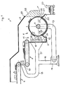
- the waste sorting device shown in FIG. 1, designated overall by 1 comprises in a housing reproduced with individual walls 2, 3, two series-connected belt conveyors 4, 5, which lead to a sieve drum 6, which according to an arrow 7 clockwise and thus on the side facing the feeders 4, 5 about a horizontal axis of rotation 8 upwards turns.
- the screen drum 6 In this area of the upward rotation, which will be referred to as steep face 9 below, the screen drum 6 is opposite a screen wall 10 and a chute 11 is formed between the two and ends in a conveyor trough 12 on the underside.
- the sieve drum 6 is connected on the inside via a suction pipe 13 to the suction side of a blower 14 and is thus able to suck in material falling in the chute 11 and, in any case, to adhere it to the top if this material is flat and, based on the contact surface, does not close is difficult. Heavier and in particular non-flat pieces of material in a waste stream supplied via the conveyors 4 and 5 cannot hold onto the screening drum and fall into the conveyor trough 12, from where they are transported away in a conventional manner.
- a directed cross-air flow is formed in accordance with the arrows 15 from the screen wall 10 to the steep surface 9, a blower duct 16, 17 leading from the blower 14 to the screen wall on the pressure side and blowing air being applied to it
- Closed recirculation duct 13, 16, 17 also has the advantage that the air loaded with fine parallels is not mixed with the outside air and the contaminants do not get out. In this respect, the effectiveness of filters which (not shown) are provided in the suction line 13 is not important.
- a branch line 18 leads from the pressure line 16 to an orifice 19, in front of which the supplied material from the conveyor 4 falls on the conveyor 5. Blowing at this point has the effect of moving and separating the material. This also promotes the efficiency of the separation provided on the screen drum 6.
- the flat material drawn off from the falling material flow by the sieve drum 6 is discharged on the side remote from the steep surface 9 in the region of an ejection opening 20, a wiping edge 21 on a chute 22 coming close to the sieve drum 6.
- the stripped and slipping material arrives in a conveyor trough 23 and thus takes a different route to the material falling into the conveyor trough 12.
- the sieve drum 6 extends outside the housing.
- a cover 25 is arranged on the inside of the drum, which closes the aforementioned area and rests on the end of the screen drum with sealing edges 26, 27. It is quite desirable for the material to be ejected towards the conveyor trough 23 that the suction effect in the area of the scraper edge 21 is eliminated. In this sense, the cover 25 together with the scraper edge 27 can also be pulled up (at most up to the vertical plane through the axis 8).
- the suction effect left on the right drum side is used to attract a flap 28 against the sieve drum.
- the system is also improved by the dead weight of the flap, the center of gravity of which in the drawing is to the right of a hinge 29 as a connection to the housing wall 2. With this flap, the large-scale entry of incorrect air is prevented, but at the same time the ejection of material is ensured.
- the device 1 represents a largely closed system with regard to the air flow.
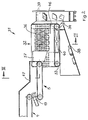
- the device shown in FIGS. 2 and 3, designated overall by 31, represents a modification compared to device 1 described above with reference to FIG. 1 in that it does not use a sieve drum with a horizontal axis, but rather a conveyor belt 32, which is between two rollers 33 , 34 revolves with (parallel to one another) inclined, namely laterally inclined axes (cf. axis 35 in FIG. 3). With its inclined surface, the conveyor belt 32 forms a steep surface 36 with a plurality of conveying directions, in that material arriving from left to right via feed conveyors 4 and 5 (corresponding to those in FIG.
- the steep face 36 is acted upon with suction air at the rear.
- FIG. 3 it can be seen with a section through the conveyor belt 32 that this encloses a fixed suction box 40 which has closed walls 41, 42 on several sides, but has a support surface 43 with large openings toward the steep face 36.
- the suction box 40 opens into a suction line 44 to a blower 45.
- the function of the device 31 differs from that of the device 1 in that the material is not sucked from a material flow in free fall, but that it is heaped onto the steep surface, from where it either passes through the steep surface 36 under the suction effect of the air flow clings or rolls off at an angle or slips.
- the separation effect is also served by a guide rail 46 at the rear and lower end of the steep face, which ensures that detachable surface material still gets into the conveyor trough 39.
- the suction box 40 takes on the one hand the function of the cover 25 in the device according to FIG. 1, but allows a simple design in connection with a conveyor belt.
- the device 31 is also not hermetically encapsulated by a housing.
- a housing part 47 ends in front of the steep surface 36 of the conveyor belt 32 and is essentially limited to air guidance functions with regard to the blower mouth 19. Although this embodiment does not achieve a hermetic seal of the air guidance, it allows the device to be simply constructed without the need for critical seals.
- the angle of inclination of the steep face 36 is 35 ° in the case shown, which is sufficient in most applications.
- steeper angles approximately 45 ° and higher, can be provided.
- a fan with a high suction capacity of, for example, 20,000 m 3 per hour is provided.
- a width of more than 0.5 m, expediently approximately 1 m, and a length of more than 0.5 m expediently 1.5 m are required.
- the perforation of the screen surface is assumed to be more than 50%.
- wire mesh belts, single belts or crossbar belts can also be used in addition to sieve belts.
- the suction box 40 the person skilled in the art also readily has surface elements which, on the one hand, are permeable to air and, on the other hand, enable the screen conveyor to be supported to any desired extent.
- the suction box 40 can also hold filter material or surface filters for trapping dusty fine particles.
- the steep surface is movable, namely as part of a sieve drum or a belt. It goes without saying that a fixed steep surface can in principle be provided in order to adhere light and flat material from a falling or sliding stream of material. This material could then be removed from the steep surface by wipers, likewise it can be provided in an intermittent operation that after the removal of heavy or rolling material the air flow through the steep surface is switched off or vice versa, in order to then throw off the flat and light material.
Landscapes
- Combined Means For Separation Of Solids (AREA)
- Refuse Collection And Transfer (AREA)
- Separation, Sorting, Adjustment, Or Bending Of Sheets To Be Conveyed (AREA)
Claims (22)
- Procédé de tri de déchets utilisant des dispositifs convoyeurs suivant un chemin de transport passant par différents postes de tri, procédé caractérisé en ce qu'on expose les déchets dans un poste de tri situé dans la partie avant de la trajectoire de transfert, à un courant d'aspiration dirigé contre une surface inclinée perméable à l'air, et les déchets s'accrochent en partie contre cette surface inclinée sous l'effet d'aspiration et sont reçus et évacués partiellement en-dessous de la surface inclinée.
- Dispositif de tri de déchets pour la mise en oeuvre du procédé selon la revendication 1, caractérisé par une surface en biais (9, 36) dont la face arrière est reliée au côté d'aspiration d'une machine soufflante (14, 45), et qui débouche au-dessus d'un convoyeur (5) et en-dessous d'un dispositif de collecte et d'évacuation (12, 38).
- Dispositif de tri de déchets selon la revendication 2, caractérisé en ce que la surface inclinée (9, 36) est réalisée de manière mobile dans une direction de mouvement (7) différente de la direction de chute.
- Dispositif de tri de déchets selon la revendication 3, caractérisé en ce que la surface inclinée (9) forme la surface d'un tambour-tamis (6) dont le volume intérieur est relié au côté aspirant d'une machine soufflante (14).
- Dispositif de tri de déchets selon la revendication 4, caractérisé en ce que le tambour-tamis (6) tourne sur un axe essentiellement horizontal (8).
- Dispositif de tri de déchets selon la revendication 5, caractérisé en ce que la surface inclinée (9) est réalisée dans la zone de rotation ascendante du tambour-tamis (6).
- Dispositif de tri de déchets selon la revendication 5 ou 6, caractérisé en ce que le tambour-tamis (6) comporte un capot (25) dans une zone située à l'extérieur de la surface inclinée (9).
- Dispositif de tri de déchets selon la revendication 7, caractérisé en ce que le capot (25) est muni d'arêtes d'étanchéité (26, 27) appliquées contre le tambour-tamis.
- Dispositif de tri de déchets selon la revendication 8, caractérisé en ce que le capot (25) est prévu sur la face intérieure du tambour-tamis (6).
- Dispositif de tri de déchets selon l'une des revendications 5 à 9, caractérisé en ce que le tambour-tamis (6) est entouré par un carter (2, 3) qui forme avec son côté opposé à la surface inclinée (9) du tambour-tamis (6), un orifice d'éjection (20) muni d'un volet d'air (28).
- Dispositif de tri de déchets selon la revendication 10, caractérisé en ce que l'orifice d'éjection (20) est muni d'une raclette (21) appliquée contre le tambour-tamis.
- Dispositif de tri de déchets selon la revendication 10 ou 11 en liaison avec l'une des revendications 7 à 9, caractérisé en ce que le capot (25) arrive jusqu'à l'orifice d'éjection 20.
- Dispositif de tri de déchets selon l'une des revendications 10 à 12, caractérisé en ce que le carter forme un sas de chute (11) avec une paroi de tamis (10) opposée à la surface inclinée (9).
- Dispositif d tri de déchets selon la revendication 13, caractérisé en ce que le sas de chute (11) est fermé dans sa partie inférieure par une goulotte d'évacuation (12).
- Dispositif de tri de déchets selon la revendication 13 ou 14, caractérisé en ce que la paroi formant tamis (10) est alimentée par sa face extérieure avec de l'air soufflé.
- Dispositif de tri de déchets selon l'une des revendications 2 à 15, caractérisé en ce qu'il comprend un carter (2, 3, 47) avec au moins un convoyeur d'alimentation (4, 5) et une alimentation en air soufflé (19) dirigé vers le haut dans la zone de transfert du convoyeur.
- Dispositif de tri de déchets selon la revendication 3, caractérisé en ce que la surface inclinée (36) est formée par une bande transporteuse (32) munie de passages.
- Dispositif de tri de déchets selon la revendication 17, caractérisé en ce que la bande transporteuse (32) est inclinée vers le côté.
- Dispositif de tri de déchets selon la revendication 18, caractérisé en ce que l'angle d'inclinaison de la bande transporteuse (32) est au moins égal à 35° et de préférence égal à 45°.
- Dispositif de tri de déchets selon les revendications 17, 18 ou 19, caractérisé en ce que la bande transporteuse (32) est une bande formant tamis.
- Dispositif de tri de déchets selon les revendications 17, 18 ou 19, caractérisé en ce que la bande transporteuse est une bande à lattes transversales.
- Dispositif de tri de déchets selon les revendications 17, 18 ou 19, caractérisé en ce que la bande transporteuse est formée de plusieurs brins formés par des bandes circulant en parallèle.
Priority Applications (1)
| Application Number | Priority Date | Filing Date | Title |
|---|---|---|---|
| AT88110265T ATE79790T1 (de) | 1987-08-12 | 1988-06-28 | Verfahren zur muellsortierung und muellsortiervorrichtung. |
Applications Claiming Priority (2)
| Application Number | Priority Date | Filing Date | Title |
|---|---|---|---|
| DE19873726808 DE3726808A1 (de) | 1987-08-12 | 1987-08-12 | Verfahren zur muellsortierung und muellsortiervorrichtung |
| DE3726808 | 1987-08-12 |
Publications (3)
| Publication Number | Publication Date |
|---|---|
| EP0303034A2 EP0303034A2 (fr) | 1989-02-15 |
| EP0303034A3 EP0303034A3 (en) | 1990-01-10 |
| EP0303034B1 true EP0303034B1 (fr) | 1992-08-26 |
Family
ID=6333581
Family Applications (1)
| Application Number | Title | Priority Date | Filing Date |
|---|---|---|---|
| EP19880110265 Expired - Lifetime EP0303034B1 (fr) | 1987-08-12 | 1988-06-28 | Procédé et dispositif pour le tri de déchets |
Country Status (3)
| Country | Link |
|---|---|
| EP (1) | EP0303034B1 (fr) |
| AT (1) | ATE79790T1 (fr) |
| DE (2) | DE8718045U1 (fr) |
Cited By (2)
| Publication number | Priority date | Publication date | Assignee | Title |
|---|---|---|---|---|
| DE4415069A1 (de) * | 1993-04-30 | 1994-11-03 | Hoema Maschinenbau Gmbh & Co K | Vorrichtung zum Trennen von Gegenständen |
| CN112791990A (zh) * | 2021-04-06 | 2021-05-14 | 建研建材有限公司 | 一种装修垃圾分选系统及分选工艺 |
Families Citing this family (26)
| Publication number | Priority date | Publication date | Assignee | Title |
|---|---|---|---|---|
| MX9201132A (es) * | 1991-03-14 | 1992-10-01 | Wellman Inc | Metodo y aparato para separar articulos de plastico |
| DE4140584C2 (de) * | 1991-12-10 | 1995-01-26 | Hans Schmitt | Vorrichtung zum Trennen einer Materialmischung aus Materialien mit unterschiedlichem spezifischen Gewicht |
| DE9204985U1 (de) * | 1992-04-10 | 1993-08-05 | Horstmann-Fördertechnik GmbH & Co KG, 32545 Bad Oeynhausen | Vorrichtung zum Sortieren der wiederverwendbaren Wertstoffe von Kunststoff- und Verbundabfällen im dualen Entsorgungssystem |
| DE4317155C2 (de) * | 1992-05-22 | 1994-09-29 | Noell Abfall & Energietech | Vorrichtung zur Separierung von Folien |
| NL9300421A (nl) * | 1992-11-17 | 1994-06-16 | Stork Protecon Bv | Inrichting voor het scheiden van de componenten uit een samengestelde hoeveelheid materiaal. |
| DE4337303A1 (de) * | 1993-11-02 | 1995-05-04 | Avermann Maschinenfabrik Betri | Sortieranlage |
| DE4413288C2 (de) * | 1994-04-16 | 1996-05-15 | Albert Sax | Vorrichtung zur Selektion von Bauschutt |
| DE19520486C2 (de) * | 1994-06-24 | 1999-08-12 | Iwa Ingenieurbuero Wolfgang Ad | Verfahren und Anlage zur Abtrennung von Leichtstoffteilchen |
| AT401740B (de) * | 1994-12-27 | 1996-11-25 | Binder Co Ag | Vorrichtung zum trennen von flächig und räumlich ausgeprägten körpern |
| DE10105120A1 (de) * | 2001-02-05 | 2002-08-22 | Westeria Foerdertechnik Gmbh | Trennvorrichtung zum Trennen leichter Stoffe aus einem Luftstrom |
| DE102005006610B4 (de) * | 2005-02-11 | 2012-02-09 | Dsg Disposal Systems Gmbh | Verfahren zur Verarbeitung von Müll sowie Vorrichtung zur Durchführung dieses Verfahrens |
| DE102005008210B4 (de) * | 2005-02-22 | 2009-08-20 | Seiringer Umwelttechnik Gmbh | Verfahren und Vorrichtung zur Sichtung eines Materialien-Gemisches |
| WO2007119254A1 (fr) * | 2006-04-18 | 2007-10-25 | Sgm Gantry S.P.A. | Séparateur balistique |
| GB0622726D0 (en) | 2006-11-15 | 2006-12-27 | Ken Mills Engineering Ltd | Material sorting apparatus |
| WO2010142986A1 (fr) * | 2009-06-09 | 2010-12-16 | Waste Systems Limited | Appareillage et procédés de tri de déchets |
| EP2461916B1 (fr) * | 2009-08-26 | 2015-04-08 | Dirk Barnstedt | Dispositif et procédé permettant de séparer des solides bidimensionnels et tridimensionnels |
| DE102010045309A1 (de) | 2010-09-14 | 2012-03-15 | Dirk Barnstedt | Verfahren zum Trennen von flächigen und körperförmigen Feststoffen in einem Schüttgutstrom |
| CN104325574A (zh) * | 2014-09-30 | 2015-02-04 | 长沙中联重科环卫机械有限公司 | 一种垃圾分选设备 |
| DE102015119040A1 (de) * | 2015-11-05 | 2017-05-11 | Terrot Gmbh | Vorrichtung und Verfahren zur Herstellung von Maschenware |
| CN105537117A (zh) * | 2016-02-26 | 2016-05-04 | 中材装备集团有限公司 | 用于建筑垃圾资源化处理的轻质物料空气分选机 |
| US10441977B2 (en) * | 2017-06-02 | 2019-10-15 | Matthew J. SKINNER | Single stream of air for separating mixed waste stream into three fractions |
| CN107961977A (zh) * | 2017-12-18 | 2018-04-27 | 韩学刚 | 一种粉料风选除渣装置 |
| CN110371515B (zh) * | 2019-07-19 | 2021-07-06 | 中国联合网络通信集团有限公司 | 垃圾分类管理系统 |
| CN115285504A (zh) * | 2022-07-28 | 2022-11-04 | 文博 | 一种电子元器件存储装置 |
| CN117225712B (zh) * | 2023-11-15 | 2024-01-16 | 山东力客智能科技有限公司 | 一种具有图像识别功能的快递分拣机 |
| CN117920584B (zh) * | 2024-03-19 | 2024-06-18 | 山东华信工业科技有限公司 | 用于碳化硅陶瓷制备的气流式原料筛选分级装置 |
Family Cites Families (8)
| Publication number | Priority date | Publication date | Assignee | Title |
|---|---|---|---|---|
| FR1138501A (fr) * | 1955-01-15 | 1957-06-14 | Installation de triage pour les produits bruts dans une machine à cueillir le houblon | |
| CH474295A (de) * | 1967-12-04 | 1969-06-30 | Meyer Maschinen Und Muehlenbau | Steigsichter für Schüttgut |
| US3836085A (en) * | 1971-03-18 | 1974-09-17 | V Brown | Tower extractor for municipal wastes |
| CH575785A5 (fr) * | 1975-02-27 | 1976-05-31 | Goergen Fritz Aurel | |
| US4165278A (en) * | 1977-10-04 | 1979-08-21 | Irving Jaffey | Separator for shredded materials |
| DE2929142A1 (de) * | 1979-07-19 | 1981-02-05 | Babcock Krauss Maffei Ind | Verfahren und vorrichtung zum sichten von grobkoernigem gut in einem horizontalsichtstrom |
| IT8148904A0 (it) * | 1981-07-15 | 1981-07-15 | Tecnicomplex Spa | Procedimento di separazione di materiali di peso specifico diverso e dispositivo per la realizzazione didetto procedimento particolarmente adatti per eliminare le impurita'pesanti contenute nel composto ottenuto dai rifiuti solidi urbani |
| DD210847A1 (de) * | 1982-11-03 | 1984-06-27 | Wtz F Betriebswirtschaftl Bera | Kombination einer kraut- und steinentfernungsvorrichtung mittels luft |
-
1987
- 1987-08-12 DE DE8718045U patent/DE8718045U1/de not_active Expired - Lifetime
- 1987-08-12 DE DE19873726808 patent/DE3726808A1/de not_active Withdrawn
-
1988
- 1988-06-28 EP EP19880110265 patent/EP0303034B1/fr not_active Expired - Lifetime
- 1988-06-28 AT AT88110265T patent/ATE79790T1/de active
Cited By (3)
| Publication number | Priority date | Publication date | Assignee | Title |
|---|---|---|---|---|
| DE4415069A1 (de) * | 1993-04-30 | 1994-11-03 | Hoema Maschinenbau Gmbh & Co K | Vorrichtung zum Trennen von Gegenständen |
| CN112791990A (zh) * | 2021-04-06 | 2021-05-14 | 建研建材有限公司 | 一种装修垃圾分选系统及分选工艺 |
| CN112791990B (zh) * | 2021-04-06 | 2021-07-02 | 建研建材有限公司 | 一种装修垃圾分选系统及分选工艺 |
Also Published As
| Publication number | Publication date |
|---|---|
| DE8718045U1 (de) | 1993-01-14 |
| EP0303034A2 (fr) | 1989-02-15 |
| ATE79790T1 (de) | 1992-09-15 |
| EP0303034A3 (en) | 1990-01-10 |
| DE3726808A1 (de) | 1989-02-23 |
Similar Documents
| Publication | Publication Date | Title |
|---|---|---|
| EP0303034B1 (fr) | Procédé et dispositif pour le tri de déchets | |
| DE69308025T2 (de) | Vorrichtung und verfahren zum trennen von wiederverwertbarem material | |
| EP0154599A1 (fr) | Installation de tirage, notamment pour extraire des produits de valeur de déchets ménagers, industriels, encombrants, secs et/ou de matières dangereuses et posant un problème | |
| DE2037500A1 (de) | Vorrichtung zur Wiedergewinnung von Papierstucken aus einer Mischung zerschmtzel ten Abfallmatenals | |
| EP0331903B1 (fr) | Dispositif de préparation d'échantillons en provenance d'un écoulement de produits en vrac | |
| EP2042244A2 (fr) | Procédé et dispositif destinés à supprimer des poussières et/ou des impuretés en forme de fibres d'un granulé de matière synthétique | |
| EP0265669B1 (fr) | Machine à trier | |
| DE68921690T2 (de) | Verfahren und Vorrichtung zum Trennen von unzulässigen Teilchen aus Tabakmaterial. | |
| EP0633067A2 (fr) | Dispositif pour l'élimination ou pour la séparation de matériaux de densités différentes à partir d'un mélange de matières | |
| DE19501263C2 (de) | Verfahren und Vorrichtung zur Sichtung eines Materialien-Gemisches | |
| DE3209049C2 (de) | Vorrichtung zum Abtrennen von Leichtpartikeln aus festem Schüttgut | |
| EP0119442B1 (fr) | Appareil pour trier et séparer les éléments de valeur d'un mélange | |
| DE4413288C2 (de) | Vorrichtung zur Selektion von Bauschutt | |
| EP0439701B1 (fr) | Procédé de séparation à plusieurs étapes pour le tri et le traitement des gravats non-homogènes et installation mettant en oeuvre le procédé | |
| DE69612612T2 (de) | Verfahren und vorrichtung zur entfeuchtung von nassen waren | |
| DE2928886A1 (de) | Verfahren und vorrichtung zum mechanischen trockensortieren von heterogenen materialien, insbesondere festen haushaltabfaellen | |
| AT401740B (de) | Vorrichtung zum trennen von flächig und räumlich ausgeprägten körpern | |
| EP0565038A1 (fr) | Procédé et dispositif pour le tri de déchets | |
| DE9417627U1 (de) | Müllvorsortierer | |
| DE102005008210B4 (de) | Verfahren und Vorrichtung zur Sichtung eines Materialien-Gemisches | |
| DE2433514C2 (de) | Vorrichtung zur Abscheidung von Pulvern und Stäuben | |
| DE9415023U1 (de) | Vorrichtung zum Trennen von Schüttgutpartikeln | |
| DE19520486A1 (de) | Verfahren und Anlage zur Abtrennung von Leichtstoffteilchen | |
| DE10200842A1 (de) | Sortiervorrichtung und -Anlage, insbesondere zur Altpapiertrennung | |
| DE4401352C2 (de) | Aufbereitungsanlage für verunreinigten Bauschutt und Verfahren zum Aufbereiten von verunreinigtem Bauschutt |
Legal Events
| Date | Code | Title | Description |
|---|---|---|---|
| PUAI | Public reference made under article 153(3) epc to a published international application that has entered the european phase |
Free format text: ORIGINAL CODE: 0009012 |
|
| AK | Designated contracting states |
Kind code of ref document: A2 Designated state(s): AT CH FR LI NL |
|
| PUAL | Search report despatched |
Free format text: ORIGINAL CODE: 0009013 |
|
| AK | Designated contracting states |
Kind code of ref document: A3 Designated state(s): AT CH FR LI NL |
|
| 17P | Request for examination filed |
Effective date: 19900320 |
|
| 17Q | First examination report despatched |
Effective date: 19911223 |
|
| GRAA | (expected) grant |
Free format text: ORIGINAL CODE: 0009210 |
|
| STAA | Information on the status of an ep patent application or granted ep patent |
Free format text: STATUS: THE PATENT HAS BEEN GRANTED |
|
| AK | Designated contracting states |
Kind code of ref document: B1 Designated state(s): AT CH FR LI NL |
|
| REF | Corresponds to: |
Ref document number: 79790 Country of ref document: AT Date of ref document: 19920915 Kind code of ref document: T |
|
| ET | Fr: translation filed | ||
| PLBI | Opposition filed |
Free format text: ORIGINAL CODE: 0009260 |
|
| PLBG | Opposition deemed not to have been filed |
Free format text: ORIGINAL CODE: 0009274 |
|
| 26 | Opposition filed |
Opponent name: HORSTMANN FOERDERTECHNIK GMBH & CO. KG Effective date: 19930518 |
|
| 26D | Opposition deemed not to have been filed | ||
| NLR1 | Nl: opposition has been filed with the epo |
Opponent name: HORSTMANN FORDERTECHNIK GMBH & CO. KG. |
|
| NLXE | Nl: other communications concerning ep-patents (part 3 heading xe) |
Free format text: PAT.BUL.18/93 THE OPPOSITION SHOULD BE DEEMED NOT TO HAVE BEEN FILED |
|
| PGFP | Annual fee paid to national office [announced via postgrant information from national office to epo] |
Ref country code: CH Payment date: 19970610 Year of fee payment: 10 |
|
| PGFP | Annual fee paid to national office [announced via postgrant information from national office to epo] |
Ref country code: AT Payment date: 19980625 Year of fee payment: 11 |
|
| PGFP | Annual fee paid to national office [announced via postgrant information from national office to epo] |
Ref country code: FR Payment date: 19980626 Year of fee payment: 11 |
|
| PG25 | Lapsed in a contracting state [announced via postgrant information from national office to epo] |
Ref country code: LI Free format text: LAPSE BECAUSE OF NON-PAYMENT OF DUE FEES Effective date: 19980630 Ref country code: CH Free format text: LAPSE BECAUSE OF NON-PAYMENT OF DUE FEES Effective date: 19980630 |
|
| PGFP | Annual fee paid to national office [announced via postgrant information from national office to epo] |
Ref country code: NL Payment date: 19980630 Year of fee payment: 11 |
|
| REG | Reference to a national code |
Ref country code: CH Ref legal event code: PL |
|
| PG25 | Lapsed in a contracting state [announced via postgrant information from national office to epo] |
Ref country code: AT Free format text: LAPSE BECAUSE OF NON-PAYMENT OF DUE FEES Effective date: 19990628 |
|
| PG25 | Lapsed in a contracting state [announced via postgrant information from national office to epo] |
Ref country code: FR Free format text: THE PATENT HAS BEEN ANNULLED BY A DECISION OF A NATIONAL AUTHORITY Effective date: 19990630 |
|
| PG25 | Lapsed in a contracting state [announced via postgrant information from national office to epo] |
Ref country code: NL Free format text: LAPSE BECAUSE OF NON-PAYMENT OF DUE FEES Effective date: 20000101 |
|
| NLV4 | Nl: lapsed or anulled due to non-payment of the annual fee |
Effective date: 20000101 |
|
| REG | Reference to a national code |
Ref country code: FR Ref legal event code: ST |