EP0343691A2 - Gerät zum Ändern eines Schallfeldes - Google Patents
Gerät zum Ändern eines Schallfeldes Download PDFInfo
- Publication number
- EP0343691A2 EP0343691A2 EP89109666A EP89109666A EP0343691A2 EP 0343691 A2 EP0343691 A2 EP 0343691A2 EP 89109666 A EP89109666 A EP 89109666A EP 89109666 A EP89109666 A EP 89109666A EP 0343691 A2 EP0343691 A2 EP 0343691A2
- Authority
- EP
- European Patent Office
- Prior art keywords
- processing
- signal
- sound field
- unit
- signals
- Prior art date
- Legal status (The legal status is an assumption and is not a legal conclusion. Google has not performed a legal analysis and makes no representation as to the accuracy of the status listed.)
- Granted
Links
Images


Classifications
-
- H—ELECTRICITY
- H03—ELECTRONIC CIRCUITRY
- H03G—CONTROL OF AMPLIFICATION
- H03G5/00—Tone control or bandwidth control in amplifiers
- H03G5/16—Automatic control
- H03G5/165—Equalizers; Volume or gain control in limited frequency bands
-
- H—ELECTRICITY
- H04—ELECTRIC COMMUNICATION TECHNIQUE
- H04R—LOUDSPEAKERS, MICROPHONES, GRAMOPHONE PICK-UPS OR LIKE ACOUSTIC ELECTROMECHANICAL TRANSDUCERS; ELECTRIC HEARING AIDS; PUBLIC ADDRESS SYSTEMS
- H04R3/00—Circuits for transducers
- H04R3/12—Circuits for transducers for distributing signals to two or more loudspeakers
Definitions
- This invention relates to an audio apparatus which handles digital audio signals reproduced from compact discs, digital audio tapes, and the like, and more particularly relates to a sound field reproducing apparatus for reproducing in an ordinary room a sound field equivalent to that of a concert hall or the like.
- a conventional sound field reproducing apparatus comprises: a signal input unit for receiving digital audio signals reproduced from compact discs and the like; a signal processing unit for processing the input signals by performing time delay and feedback operations on them according to a specified procedure; a processing instruction unit for instructing the signal processor how to process the input signals; a system controller for modifying the signal processing instructions; and a signal output unit for outputting the digital signals from the signal processing unit.
- the signals received by the signal input unit are processed by the signal processing unit according to the instructions indicated by the processing instruction unit, and converted to signals which are suitable for a certain sound field. Then, the outputs from the signal processing unit are supplied to an external digital-analog converter through the signal output unit so that they are converted to analog signals. Then these analog signals are audibly reproduced with a plurality of power amplifiers and loud speakers to reproduce, a desired sound field.
- the input signal is an impulse signal shown by (a) in Fig. 14
- the signal processing unit it is possible for the signal processing unit to make a plurality of impulse trains such as (b) , (c) , (d) and (e) of Fig. 14 of the signal to be input in each loud speaker, by performing time delay and adding operations.
- These impulse trains may be representative of initial reflected sounds of a certain sound field.
- Such an apparatus for modifying a sound field generally comprises: a digital audio signal input unit; a signal processing unit for processing the digital input signals in a certain way to attain the sound field characteristics to be reproduced; a processing procedure memory for storing the processing procedures according to which the signal processing unit processes the input signals; a system controller for modifying the processing procedure sent from the processing procedure memory to the signal processing unit and for providing overall controls of the system operation; and a signal output unit for outputting the digital signals.
- the digital signals received by the signal input unit are processed by the signal processing unit according to the processing procedure sent from the processing procedure memory. Then, the outputs of the signal processing unit are passed through the signal output unit, and converted to analog signals by an external D/A converter. These analog signals are then connected with amplifiers and speakers and the like so that they are rendered audible in a target sound field.
- control codes are sent from the system controller to the processing procedure memory to change the processing procedure. Upon reception of the codes, the processing procedure memory transfers associated sound field data to the signal processing unit. The subsequent operation same as described above is conducted to change the reproduced sound field.
- this invention comprises of an input means for receiving digital audio signals from compact discs and the like, a plurality of signal processing means for processing the input digital signals by performing time delay and feed back operations on them according to a specified procedure, a processing instruction means for giving instruction of processing procedures to the signal processing means, a signal switching means for smoothly switching a plurality of signals output from said signal processing means at the time of a change in the processing procedure, and a system control means for modifying the instructions of the processing instruction unit and for controlling the signal switching means.
- the processing procedure not of the first signal processing means whose outputs are passed on by the signal output means but of the second signal processing means whose output signals are not passed on by the signal output means is changed into a processing procedure corresponding to the sound field to be reproduced next.
- the sum of the signal from the first and second signal processing means is output.
- the output signals from the first signal processing means are gradually reduced while those from the second signal processing means are gradually increased until the latter alone are output in the end.
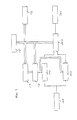
- FIG. 1 is a block diagram of an apparatus for changing a sound field of the first example of this invention.
- the reference numeral 1 is a signal input unit for receiving digital audio signals
- 2 denotes a first signal processing unit which processes the signals by performing time delay and feedback operations on the digital input signals according to a specified procedure
- 3 denotes a second signal processing unit which processes the signals by performing time delay and feedback operations on the input signals according to a specified procedure in the same way as in the first signal processing unit
- 41 and 42 are processing instruction units for giving instructions for processing procedures to the signal processors
- 5 denotes a signal switching unit for switching smoothly a plurality of output signals from the signal processing units 2 and 3 at the time of a change in the processing procedure
- 6 denotes a system controller for modifying the instructions of the processing instruction units 41 and 42 and for controlling the signal switching unit 5
- 7 denotes a signal output unit for delivering the digital output signals from the signal switching unit 5 to the outside.
- the digital input signals are processed by the first signal processing unit 2 according to a processing procedure specified in the processing instruction unit 41 , and then output through the signal switching unit 5 and signal output unit 7 to attain a desired sound field.
- the output signals from the second signal processing unit 3 are supplied to the signal switching unit 5 but not passed on farther to the signal output unit 7 .
- the system controller 6 modifies the contents of the processing instruction unit 42 in such a way that instructions of a processing procedure corresponding to the next sound field are given to the second signal processing unit 3 .
- the system controller 6 instructs the signal switching unit 5 to carry out signal switching.
- the output signals from the first and second signal processing units 2 and 3 are added while the level of the signals from the former responsible for the current sound field is reduced and the level of the signals from the latter for the next sound field increased both gradually until the signals from the second signal processing unit 3 alone are output finally. In this way, the signals are switched smoothly without producing any break.
- the above operation is performed alternately on the first and second signal processing units 2 and 3 , so that sound fields can be changed without causing noises or a break in transition from one to the next.
- Figure 2 shows the state of signals in the first example.
- (a) shows the waveform of the output signal from the first signal processing unit 2
- (c) shows the waveform of the output signal from the second signal processing unit 3 .
- the noises attributable to a change in the processing procedure are indicated by the arrows of broken line in (a) and (c) .
- (b) shows signal components output from the first signal processing unit 2 , among the output signals of the signal switching unit 5 .
- (d) shows the signal component output from the second signal processing unit 3 in the output signals of the signal switching unit 5 .
- the signals (b) and (c) are added to form the signal (e), which is output from the signal switching unit 5 .
- This output signal from the signal switching unit 5 does not contain noises due to switching. It is also free from any breaks.
- the duration of signal switching instruction from the system controller 6 is indicated by the arrows of solid line.
- FIG. 3 is a block diagram of an apparatus for changing a sound field of the second example of this invention, the configuration of which is the same as that of the first example.
- the reference numeral 101 is the signal input unit for receiving digital audio signals
- 201 is the first signal processing unit for processing the digital input signals by performing time delay and feedback opera tions according to a specified procedure on them
- 301 is the second signal processing unit which operates in the same way as in the first signal processing unit 201
- 8 is the first processing instruction unit which gives instructions for a signal processing procedure to the signal processing unit
- 9 is the second processing instruction unit
- 501 is the signal switching unit for switching output signals between the first signal processing unit 201 and the second signal processing unit 301
- 10 is the system controller for transferring codes for processing procedure selection to the first and second processing instruction units 8 and 9 and for controlling the signal switching unit 501
- 701 is the digital signal output unit.
- the apparatus for changing a sound field of the second example will be described below.
- the signals from the signal input unit 101 are processed by the signal processing unit 201 according to the processing procedure set in the first processing instruction unit 8 .
- the signal switching unit 501 selects the output signals from the first signal processing unit 201 , and selected signals are output from the signal output unit 701 .
- the second signal processing unit 301 operates in the same way as in the first signal processing unit 201 to select a processing procedure.
- the signal switching unit 501 selects the signals from the first signal process unit 201 to output them.
- FIG 4 is a memory map of the processing instruction unit.
- Figure 5 shows the listening positions of a certain concert hall. As shown in Fig. 4, the memory area is divided so as to store the processing procedures to attain the listening characteristics corresponding to the listening positions No. 1 through No. 56 shown in Fig. 5.
- the system controller 10 sends to the second processing instruction unit 9 a code for selecting an address where a processing procedure corresponding to the sound field for a new listening position is stored. For instance, when the listening position changes from A to B in Fig. 5, the processing procedures No. 11, No. 18 and No.
- the system controller 10 sends a switching signal to the signal switching unit 501 .
- the signal switching unit 501 outputs the sum of the signals output from the first and second processing units 201 and 301 while reducing the level of the signal from the former and increasing the level of the signal from the latter both gradually. After a certain period of time has passed, the output from the signal switching unit 501 consists entirely of the signals from the second signal processing unit 301 .
- the system controller 10 selects the processing procedure No. 18 of the first processing instruction unit 8 , and the above operation processes are repeated alternately. Finally the processing procedure No. 25 is set in the second processing instruction unit 9 .
- the time required for switching the processing procedure in the first processing instruction unit 8 to that in the second processing instruction unit 9 is changeable freely.
- the necessary processing procedures for continuous sound field control can be stored in the processing instruction units by a plurality of signal processing units and processing instruction units, and the system controller 10 sends only codes for selecting processing procedure, thereby enabling that the sound field can be continuously changed in real time and is free from noise at the time of data switching.
- This example is described in view of continuous shifting of the listening position. It is also possible, however, to continuously vary other data of the sound field such as the movement of the sound image, change in the perspective, etc. on a real time basis by storing necessary processing procedures in the processing instruction units.
- FIG. 6 is a block diagram of an apparatus for changing a sound field of the third example of this invention.
- the reference numeral 102 is the signal input unit for receiving digital audio signals
- 202 is the first signal processing unit which processes the input digital signals by performing time delay and feedback operations on them according to a specified procedure
- 302 is the second processing unit which operates in the same way as in the first signal process unit
- 802 is the first processing instruction unit which gives instructions for a signal processing procedure to the signal processing unit
- 902 is the second processing instruction unit
- 502 is the signal switching unit for switching output signals from the first signal processing unit 202 and the second signal processing unit 302
- 10-1 is the system controller for reading the codes recorded on media such as video tapes and audio tapes for processing procedure selection and for sending them to the first and second processing instruction units 802 and 902
- the controller controlling also the signal switching unit 502 is the digital signal output unit
- 11 is the reader for reading of the control codes from codes on media such as video tapes and audio tapes.
- the apparatus shown in Fig. 6 operates in the same way as in the second example of this invention.
- the image of a concert hall is displayed on the screen and the listening position changes continuously as if a person were listening to the music while moving about in the hall, continuous processing procedures not only for changing simply the loudness of sound but also for satisfying time delay and feedback requirements are required.
- the memory area is so divided as to store the procedures which attain the sound field characteristics corresponding to the listening positions No. 1 through No. 56 of Fig. 5.
- the system controller 10-1 sends to the second processing instruction unit 902 a code for selecting an address where a processing procedure for attaining the sound field corresponding to the new listening position is stored. For instance, when the listening position changes from A to B in Fig. 5, the processing procedures No. 11, No. 18, and No. 25 are selected sequentially in that order from the memory map of Fig. 4. The processing procedure No. 11 is selected first and the output from the second signal processing unit 302 is stabilized, then, the control code reader 11 reads a control signal from the codes on video tapes or other media. The system controller 10-1 uses this control signal to actuate the signal switching unit 502 .
- the signal switching unit 502 outputs the sum of the signals from the first and second signal processing units 202 and 302 while reducing the level of the signal from the former and increasing the level of the signal from the latter both gradually. After a certain period of time has elapsed, the output from the signal switching unit 502 is switched completely to the signals from the second signal processing unit 302 .
- the system controller 10-1 selects the processing procedure No. 18 of the first processing instruction unit 802 , and the above operation processes are repeated alternately. Finally, the processing procedure No. 25 is set in the second processing instruction unit 902 .
- FIG. 7 is a block diagram of the apparatus for changing a sound field of the fourth example of this invention.
- the reference numeral 103 is the signal input unit for receiving digital audio signals
- 703 is the signal output unit
- 203 is the first signal processing unit which processes the input digital signals by performing time delay and feedback operations on them according to a specified procedure
- 303 is the second signal processing unit which operates in the same way as in the first signal processor 203
- 12 is the processing procedure memory which store the basic procedures for signal processing
- 13 is an operation instruction unit for evaluating processing procedures by performing operations based on a certain number of basic processing procedures received from the processing procedure memory 12 and for giving instructions of the obtained processing procedures to the first and second signal processors 203 and 303
- 503 is the signal switching unit for output signal switching between the first signal processing unit 203 and the second signal process unit 303
- 14 is a display/input unit which displays the spacial shape of a sound field for reproduction and from which data on listening position and others are entered
- 15 is the system controller which receives information
- Figure 8 shows an image of a concert hall to be taken as an example of the spacial shape that is displayed on the display/input unit 14 , which is a component of the hardware of Fig. 7.
- a plan view of the concert hall is shown in this figure.
- Figure 9 gives an example of the memory area of the processing procedure memory 12 , which is another component of the hardware of Fig. 7. It shows how the sound field data corresponding to the positions A (start point) and B (end point) in the plan view of the concert hall shown in Fig. 8 is stored as the basic processing procedures.
- the system controller 15 instructs the processing procedure memory 12 to transfer the sound field data at the listening positions A and B in Fig. 8, i.e., data stored at addresses 1000 and 1020 in the memory map of Fig. 9, as the basic processing procedures for the hall.
- These basic processing procedures are received by the operation instruction unit 13 . Simultaneously only the processing procedure corresponding, for instance, to the position A is transferred to the first signal processing unit 203 .
- the signals output from the signal input unit 103 are processed by both the first and second signal processing units 203 and 303 , and then the signal switching unit 503 selects only the output signal from the second signal processing unit 303 .
- the system controller 15 issues a switching signal to the signal switching unit 503 .
- This signal causes the signal switching unit 503 to output the sum of the signals from the first and second signal processing units 203 and 303 while increasing the level of the signal of the former and reducing the level of the signal of the latter both gradually. In a certain period of time, the output from the signal switching unit 503 is switched completely to the signals from the signal processing unit 203 .
- the system controller 15 transfers the positional information on P to the operation instruction unit 13.
- the operation instruction unit 13 divides the space between the position A corresponding to the sound field of current reproduction and the position P into many points. Starting with the point nearest the position A , the sound field data for each of the many points thus produced are evaluated in sequence by performing proportional calculation based on the basic processing procedures at the positions A and B . The sound field data thus evaluated is sent to the signal processing unit in which the output of a signal is inhibited by the signal switching unit 503 .
- the processing procedure evaluated by the operation instruction unit 13 consists of the sound field data corresponding to the position (n-1) in Fig. 8
- the processing procedure is transferred to the second signal processing unit 303 .
- the system controller 15 sends a switching signal to the signal switching unit 503 . This causes the signal switching unit 503 to switch the output smoothly to the signal processed by the first signal processing unit 303 in the same way as mentioned above.
- the operation instruction unit 13 evaluates the processing procedure at the position (n) in Fig. 8 and transfers it to the first signal processing unit 203 .
- Figure 10 shows some examples of the impulse responses which represent the sound field data at the positions A and B , and examples of the impulse response at position (n) evaluated by operation.
- this invention makes it possible to reproduce many sound fields using a relatively small memory capacity and also to attain extremely smooth and continuous changes in the sound field associated with the movement of the listening position.
- This is attained by storing sound field data on two listening points in the audio space for reproduction as the basic processing procedures and by performing operations on the two basic processing procedures to evaluate processing procedures for intermediate points between the two listening positions.
- the processing procedures thus evaluated are used in signal processing for sound field reproduction at applicable intermediate points.
- many intermediate points are set on the path of the movement and the processing procedures for these points are evaluated in sequence, and signals are switched through alternate processing by a plurality of signal processing units at every evaluation of the processing procedures.
- This example of the invention attains a listening position movement in a linear pattern using two basic processing procedures.
- the number of basic processing procedures is not limited to two, and the listening position movement may be two or three dimensional.
- processing procedure evaluation depends on linear interpolation using the distance as the parameter. But such evaluation is not restricted to this.
- this example processes the movement of the listening position in a concert hall. But changes in the sound field can be dealt with. For instance, the filter characteristics may be rendered continuously variable by evaluating the filter coefficient of reproduced sounds by computation.
- FIG 11 is a block diagram of an apparatus for changing a sound field of the fifth example of this invention, the configuration of which is the same as that of the first example of this invention.
- the reference numeral 104 is the signal input unit for receiving digital audio signals
- 204 is the first signal processing unit for processing input digital signals by performing time delay and feedback operations on them according to a specified procedure
- 304 is the second signal processor which operates in the same way as in the first signal processing unit 204
- 404 and 405 are the processing instruction units for giving instructions of signal processing procedures to the signal processing units
- 504 is the signal switching unit for smoothly switching a plurality of output signals from the signal processing units 204 and 304 at the time of a change in the processing procedure
- 604 is the system controller for modifying instructions from the processing instruction units 404 and 405 and for controlling the signal switching unit 504
- 704 is the signal output unit for passing on digital signals output from the signal switching unit 504 .
- T00 T0/n (1)
- T01 T00 (2)
- the signal processing unit 204 or 304 performs signal processing according to this data.
- the processing instruction unit 404 or 405 adds T00 to T01 and sets the sum T02 as the reverberation time in the signal processing unit 204 or 304 again.
- FIG. 12 is a block diagram of an apparatus for changing a sound field of the sixth example of this invention.
- the reference numeral 105 is the signal input unit for receiving digital audio signals
- 205 is the first signal processing unit for processing the input digital signals by performing time delay and feedback operations on them according to a specified procedure
- 305 is the second signal processing unit which operates in the same way as in the first signal processing unit
- 406 and 407 are the processing instruction units for giving instructions of signal processing procedures to the signal processing units
- 505 is the signal switching unit for smoothly switching a plurality of output signals from the signal processing units 205 and 305 at the time of a change in the processing procedure
- 605 is the system controller for modifying instructions from the processing instruction units 406 and 407 and for controlling the signal switching unit 505
- 705 is the signal output unit for passing on digital signals output from the signal switching unit 505
- 16 is a variable resistor group
- 17 is a resistance converter
- 18 is an amplifier
- 19 is a loud speaker unit.
- the resistance converter 17 detects the direction of sound image movement according to the resistance measured using the variable resistance group 16 .
- the delay time, amplitude, etc. necessary for orienting the sound image are then evaluated for each reproduction speaker unit and set in the processing instruction unit 406 or 407 .
- the processing instruction unit 406 or 407 converts them into data items acceptable by the signal processing unit 205 or 305 and sets them therein for signal processing.
- the signals having been processed in terms of time delay, amplitude, etc. are output from the speaker unit 19 through the signal output unit 705 and amplifier 18 .
- variable resistor group configuration shown in Fig. 13 is applicable for two-dimensional sound field space control.
- the reference numeral 20 is a control rod
- 21 and 22 are variable resistors
- 23 , 24 , 25 , 26 , 27 and 28 are terminals.
- the terminal on each end of the variable resistors 21 and 22 are fixed, but the terminals in the middle are designed to change their position according to the movement of the control rod 20 . Therefore, they make it possible to indicate the position vector decomposed in the longitudinal and lateral directions of the control rod.
- the terminal 24 in the middle of the variable resistor 21 is used to detect the resistances between the terminals 23 and 24 and between the terminals 25 and 24 , and the voltage r1 across the terminals 23 and 24 , and the voltage r2 across the terminals 25 and 24 are measured.
- the terminal 26 in the middle of the variable resistor 22 is used similarly to detect the resistance between the terminals 26 and 27 and between the terminals 27 and 28 , and the voltage r3 across the terminals 26 and 27 and the voltage r4 across the terminals 27 and 28 are measured.
- the vector in the longitudinal direction is represented by the two variables r1 and r2 .
- the vector in the lateral direction is represented by the two variables r3 and r4 .
- the position vector of the control rod is determined by the four variables in total.
Landscapes
- Health & Medical Sciences (AREA)
- General Health & Medical Sciences (AREA)
- Otolaryngology (AREA)
- Physics & Mathematics (AREA)
- Engineering & Computer Science (AREA)
- Acoustics & Sound (AREA)
- Signal Processing (AREA)
- Stereophonic System (AREA)
Applications Claiming Priority (12)
| Application Number | Priority Date | Filing Date | Title |
|---|---|---|---|
| JP63130673A JPH0832120B2 (ja) | 1988-05-27 | 1988-05-27 | 音場可変装置 |
| JP130672/88 | 1988-05-27 | ||
| JP63130672A JPH0832119B2 (ja) | 1988-05-27 | 1988-05-27 | 音場可変装置 |
| JP63130671A JPH01300697A (ja) | 1988-05-27 | 1988-05-27 | 音場可変装置 |
| JP63130670A JPH01300695A (ja) | 1988-05-27 | 1988-05-27 | 音場可変装置用入力装置 |
| JP130673/88 | 1988-05-27 | ||
| JP130671/88 | 1988-05-27 | ||
| JP130670/88 | 1988-05-27 | ||
| JP63216561A JP2523810B2 (ja) | 1988-08-31 | 1988-08-31 | 音場可変装置 |
| JP216561/88 | 1988-08-31 | ||
| JP63248120A JPH0295100A (ja) | 1988-09-30 | 1988-09-30 | 音場可変装置 |
| JP248120/88 | 1988-09-30 |
Publications (3)
| Publication Number | Publication Date |
|---|---|
| EP0343691A2 true EP0343691A2 (de) | 1989-11-29 |
| EP0343691A3 EP0343691A3 (de) | 1991-02-27 |
| EP0343691B1 EP0343691B1 (de) | 1996-03-06 |
Family
ID=27552765
Family Applications (1)
| Application Number | Title | Priority Date | Filing Date |
|---|---|---|---|
| EP89109666A Expired - Lifetime EP0343691B1 (de) | 1988-05-27 | 1989-05-29 | Gerät zum Ändern eines Schallfeldes |
Country Status (3)
| Country | Link |
|---|---|
| US (1) | US5023913A (de) |
| EP (1) | EP0343691B1 (de) |
| DE (1) | DE68925834T2 (de) |
Cited By (2)
| Publication number | Priority date | Publication date | Assignee | Title |
|---|---|---|---|---|
| FR2738099A1 (fr) * | 1995-08-25 | 1997-02-28 | France Telecom | Procede de simulation de la qualite acoustique d'une salle et processeur audio-numerique associe |
| WO2005106843A1 (en) * | 2004-04-30 | 2005-11-10 | Axeon Limited | Reproduction control of an audio signal based on musical genre classification |
Families Citing this family (12)
| Publication number | Priority date | Publication date | Assignee | Title |
|---|---|---|---|---|
| US5495534A (en) * | 1990-01-19 | 1996-02-27 | Sony Corporation | Audio signal reproducing apparatus |
| KR940011504B1 (ko) * | 1991-12-07 | 1994-12-19 | 삼성전자주식회사 | 2채널 음장재생 장치 및 방법 |
| JPH08502867A (ja) * | 1992-10-29 | 1996-03-26 | ウィスコンシン アラムニ リサーチ ファンデーション | 指向性音を作る方法及び装置 |
| GB9307934D0 (en) * | 1993-04-16 | 1993-06-02 | Solid State Logic Ltd | Mixing audio signals |
| US5438623A (en) * | 1993-10-04 | 1995-08-01 | The United States Of America As Represented By The Administrator Of National Aeronautics And Space Administration | Multi-channel spatialization system for audio signals |
| EP0691623B1 (de) * | 1994-07-04 | 2001-10-04 | Hewlett-Packard Company, A Delaware Corporation | Kritzlervergleich |
| DE19645867A1 (de) | 1996-11-07 | 1998-05-14 | Deutsche Telekom Ag | Verfahren zur mehrkanaligen Tonübertragung |
| US6243476B1 (en) | 1997-06-18 | 2001-06-05 | Massachusetts Institute Of Technology | Method and apparatus for producing binaural audio for a moving listener |
| US6125115A (en) * | 1998-02-12 | 2000-09-26 | Qsound Labs, Inc. | Teleconferencing method and apparatus with three-dimensional sound positioning |
| CN101027939A (zh) * | 2004-09-22 | 2007-08-29 | 皇家飞利浦电子股份有限公司 | 多通道音频控制 |
| JP2006340057A (ja) * | 2005-06-02 | 2006-12-14 | Yamaha Corp | アレースピーカ装置 |
| CN111292757B (zh) * | 2013-09-12 | 2024-05-24 | 杜比国际公司 | 基于qmf的处理数据的时间对齐 |
Family Cites Families (5)
| Publication number | Priority date | Publication date | Assignee | Title |
|---|---|---|---|---|
| NL7614040A (nl) * | 1976-12-17 | 1978-06-20 | Novanex Automation Nv | Electronische echo-inrichting. |
| DE3034756C2 (de) * | 1979-09-18 | 1986-09-04 | Victor Company Of Japan, Ltd., Yokohama, Kanagawa | Audiosignalverarbeitungseinrichtung |
| US4389915A (en) * | 1980-12-18 | 1983-06-28 | Marmon Company | Musical instrument including electronic sound reverberation |
| GB2194658B (en) * | 1985-08-02 | 1989-08-16 | Ant Nachrichtentech | Transfer circuit and transfer process for the transfer of co-efficients |
| US4792974A (en) * | 1987-08-26 | 1988-12-20 | Chace Frederic I | Automated stereo synthesizer for audiovisual programs |
-
1989
- 1989-05-26 US US07/358,282 patent/US5023913A/en not_active Expired - Lifetime
- 1989-05-29 EP EP89109666A patent/EP0343691B1/de not_active Expired - Lifetime
- 1989-05-29 DE DE68925834T patent/DE68925834T2/de not_active Expired - Lifetime
Cited By (3)
| Publication number | Priority date | Publication date | Assignee | Title |
|---|---|---|---|---|
| FR2738099A1 (fr) * | 1995-08-25 | 1997-02-28 | France Telecom | Procede de simulation de la qualite acoustique d'une salle et processeur audio-numerique associe |
| US5812674A (en) * | 1995-08-25 | 1998-09-22 | France Telecom | Method to simulate the acoustical quality of a room and associated audio-digital processor |
| WO2005106843A1 (en) * | 2004-04-30 | 2005-11-10 | Axeon Limited | Reproduction control of an audio signal based on musical genre classification |
Also Published As
| Publication number | Publication date |
|---|---|
| US5023913A (en) | 1991-06-11 |
| DE68925834T2 (de) | 1996-08-08 |
| EP0343691B1 (de) | 1996-03-06 |
| DE68925834D1 (de) | 1996-04-11 |
| EP0343691A3 (de) | 1991-02-27 |
Similar Documents
| Publication | Publication Date | Title |
|---|---|---|
| US5023913A (en) | Apparatus for changing a sound field | |
| EP1017166B1 (de) | Vorrichtung zur Veränderung akustischer Eigenschaften | |
| EP0356995B1 (de) | Gerät zum Übermitteln von Steuercodes zu einem Schallfeldwiedergabegerät | |
| JPH0746687A (ja) | 音響特性補正装置 | |
| US4937875A (en) | Audio signal processing apparatus | |
| JP2956125B2 (ja) | 音源情報制御装置 | |
| JP2523810B2 (ja) | 音場可変装置 | |
| JP2002058100A (ja) | 音像定位制御装置および音像定位制御プログラムが記録された記録媒体 | |
| JPH01300699A (ja) | 音場可変装置 | |
| US5434923A (en) | Acoustic apparatus | |
| JP2538057B2 (ja) | 音場可変装置 | |
| JP2550327Y2 (ja) | オーディオ再生装置 | |
| JP2951511B2 (ja) | 音響装置 | |
| JP2003302979A (ja) | 音場再生装置及びその制御方法、プログラム及び記録媒体 | |
| JPH01300698A (ja) | 音場可変装置 | |
| JPH06225400A (ja) | 音場制御装置 | |
| KR0169627B1 (ko) | 음성신호를 시간단위로 반복 재생하는 방법 | |
| JPH034610A (ja) | 音響機器 | |
| JPH04341000A (ja) | 音響装置 | |
| JPH04246705A (ja) | 物理量制御装置 | |
| JPH0744096Y2 (ja) | 音場制御装置 | |
| JPH0295100A (ja) | 音場可変装置 | |
| JPH0366299A (ja) | 音場可変装置 | |
| JPH02172400A (ja) | 音場可変制御装置 | |
| JPH04347917A (ja) | ムービングフェーダー制御方法 |
Legal Events
| Date | Code | Title | Description |
|---|---|---|---|
| PUAI | Public reference made under article 153(3) epc to a published international application that has entered the european phase |
Free format text: ORIGINAL CODE: 0009012 |
|
| 17P | Request for examination filed |
Effective date: 19890728 |
|
| AK | Designated contracting states |
Kind code of ref document: A2 Designated state(s): DE FR GB NL |
|
| RIN1 | Information on inventor provided before grant (corrected) |
Inventor name: HASHIMOTO, HIKARI Inventor name: MATSUMOTO, MASAHARU Inventor name: SATO, KATSUAKI Inventor name: SERIKAWA, MITSUHIKO Inventor name: KAWAMURA, AKIHISA Inventor name: ISHIKAWA, SEIICHI |
|
| PUAL | Search report despatched |
Free format text: ORIGINAL CODE: 0009013 |
|
| AK | Designated contracting states |
Kind code of ref document: A3 Designated state(s): DE FR GB NL |
|
| RHK1 | Main classification (correction) |
Ipc: H03G 3/00 |
|
| 17Q | First examination report despatched |
Effective date: 19940310 |
|
| GRAH | Despatch of communication of intention to grant a patent |
Free format text: ORIGINAL CODE: EPIDOS IGRA |
|
| GRAA | (expected) grant |
Free format text: ORIGINAL CODE: 0009210 |
|
| AK | Designated contracting states |
Kind code of ref document: B1 Designated state(s): DE FR GB NL |
|
| REF | Corresponds to: |
Ref document number: 68925834 Country of ref document: DE Date of ref document: 19960411 |
|
| ET | Fr: translation filed | ||
| PLBE | No opposition filed within time limit |
Free format text: ORIGINAL CODE: 0009261 |
|
| STAA | Information on the status of an ep patent application or granted ep patent |
Free format text: STATUS: NO OPPOSITION FILED WITHIN TIME LIMIT |
|
| 26N | No opposition filed | ||
| REG | Reference to a national code |
Ref country code: GB Ref legal event code: IF02 |
|
| REG | Reference to a national code |
Ref country code: GB Ref legal event code: 746 Effective date: 20031002 |
|
| REG | Reference to a national code |
Ref country code: FR Ref legal event code: D6 |
|
| PGFP | Annual fee paid to national office [announced via postgrant information from national office to epo] |
Ref country code: DE Payment date: 20080605 Year of fee payment: 20 |
|
| PGFP | Annual fee paid to national office [announced via postgrant information from national office to epo] |
Ref country code: NL Payment date: 20080501 Year of fee payment: 20 |
|
| PGFP | Annual fee paid to national office [announced via postgrant information from national office to epo] |
Ref country code: GB Payment date: 20080604 Year of fee payment: 20 |
|
| REG | Reference to a national code |
Ref country code: FR Ref legal event code: ST Effective date: 20090119 |
|
| PG25 | Lapsed in a contracting state [announced via postgrant information from national office to epo] |
Ref country code: FR Free format text: LAPSE BECAUSE OF NON-PAYMENT OF DUE FEES Effective date: 20080602 |
|
| REG | Reference to a national code |
Ref country code: GB Ref legal event code: PE20 Expiry date: 20090528 |
|
| REG | Reference to a national code |
Ref country code: FR Ref legal event code: D3 |
|
| PG25 | Lapsed in a contracting state [announced via postgrant information from national office to epo] |
Ref country code: NL Free format text: LAPSE BECAUSE OF EXPIRATION OF PROTECTION Effective date: 20090529 |
|
| NLV7 | Nl: ceased due to reaching the maximum lifetime of a patent |
Effective date: 20090529 |
|
| PG25 | Lapsed in a contracting state [announced via postgrant information from national office to epo] |
Ref country code: GB Free format text: LAPSE BECAUSE OF EXPIRATION OF PROTECTION Effective date: 20090528 |
|
| PGFP | Annual fee paid to national office [announced via postgrant information from national office to epo] |
Ref country code: FR Payment date: 20080514 Year of fee payment: 20 |