EP0343550A2 - Prise électrique pour contacts plats - Google Patents
Prise électrique pour contacts plats Download PDFInfo
- Publication number
- EP0343550A2 EP0343550A2 EP89109140A EP89109140A EP0343550A2 EP 0343550 A2 EP0343550 A2 EP 0343550A2 EP 89109140 A EP89109140 A EP 89109140A EP 89109140 A EP89109140 A EP 89109140A EP 0343550 A2 EP0343550 A2 EP 0343550A2
- Authority
- EP
- European Patent Office
- Prior art keywords
- cage
- flat
- contact
- quiver
- protective sleeve
- Prior art date
- Legal status (The legal status is an assumption and is not a legal conclusion. Google has not performed a legal analysis and makes no representation as to the accuracy of the status listed.)
- Granted
Links
Images


Classifications
-
- H—ELECTRICITY
- H01—ELECTRIC ELEMENTS
- H01R—ELECTRICALLY-CONDUCTIVE CONNECTIONS; STRUCTURAL ASSOCIATIONS OF A PLURALITY OF MUTUALLY-INSULATED ELECTRICAL CONNECTING ELEMENTS; COUPLING DEVICES; CURRENT COLLECTORS
- H01R13/00—Details of coupling devices of the kinds covered by groups H01R12/70 or H01R24/00 - H01R33/00
- H01R13/02—Contact members
- H01R13/10—Sockets for co-operation with pins or blades
- H01R13/11—Resilient sockets
- H01R13/113—Resilient sockets co-operating with pins or blades having a rectangular transverse section
-
- H—ELECTRICITY
- H01—ELECTRIC ELEMENTS
- H01R—ELECTRICALLY-CONDUCTIVE CONNECTIONS; STRUCTURAL ASSOCIATIONS OF A PLURALITY OF MUTUALLY-INSULATED ELECTRICAL CONNECTING ELEMENTS; COUPLING DEVICES; CURRENT COLLECTORS
- H01R13/00—Details of coupling devices of the kinds covered by groups H01R12/70 or H01R24/00 - H01R33/00
- H01R13/40—Securing contact members in or to a base or case; Insulating of contact members
- H01R13/42—Securing in a demountable manner
- H01R13/428—Securing in a demountable manner by resilient locking means on the contact members; by locking means on resilient contact members
- H01R13/432—Securing in a demountable manner by resilient locking means on the contact members; by locking means on resilient contact members by stamped-out resilient tongue snapping behind shoulder in base or case
Definitions
- the invention is directed to a flat plug connection of the type specified in the preamble of claim 1.
- the socket member has a C-shaped flat profile, the profile leg ends of which are rolled up and in the case of coupling with one blade surface contact the knife contact member on the male part, while the opposite blade surface is spring-loaded by a tongue formed on the C-profile web and bent back into the profile interior.
- the C-legs merge with longitudinal edges into the C-web connecting them and form a receiving channel containing the tongue, which only touches the knife contact element in places.
- the areas of the C-leg located on the narrow sides of the flat profile do not come into contact with the knife edges of the male part.
- In order to improve the contact one had to rely on a high spring load to be exerted by the tongue, which, however, had the disadvantage of requiring a high plug-on force on the die part when the knife contact element was engaged.
- the invention has for its object to develop a space-saving tab connector due to the knife contact member of the type mentioned in the preamble of claim 1, which on the one hand has good contacting and on the other hand manages with low insertion forces during the coupling process.
- the invention has made it possible to reconcile these two apparently contradicting demands for good contact and low attachment forces and is characterized by the following special features.
- the socket member is equipped as a rectangular tube with webs created by longitudinal slots on all tube sides, contact webs also come to rest on the rectangular narrow sides, which come into contact with the knife edges of the male part in the event of a coupling.
- the socket member is thus designed on all sides as a cage, the cage webs of which have single or multiple kinks or arches and thus run in a V or W shape.
- the kink or arch apex produced in this way springs on all sides against the knife contact element coupled into the interior of the cage and is effective in contact. This gives contact points distributed over the entire circumference of the profile, which summatively produce a large contact area.
- Each kinked or curved contact web is under its own spring load due to its V- or W-shape, which is sufficient for good contacting, but due to the very slim, long web shape requires surprisingly low attachment forces during the coupling process to deform it.
- the course of the kink or curve is leveled in the contact web and contacts with its apex. Coupling is thus easy and you get a good electrical transition even for higher electrical currents.
- a single kink in each contact web, which establishes a V-shaped web profile, is particularly advantageous.
- plug connectors DE-PS 35 02 633
- the socket member is designed as a full rectangular tube, but this does not have a cage structure, but on the broad sides molded, mutually curved spring arm pairs, on which a pair of reinforcing springs presses, in a corresponding manner Is integrally formed on a reinforcing sleeve to be pushed over the socket member.
- the contact webs located on the narrow sides of the cage can, as proposed in claim 4, be designed symmetrically because they are then deformed in time between the aforementioned asymmetrical kinks or bends of the other contact webs when coupling.
- the simplest version of the die part can be formed in one piece.
- This sheet material is, according to claim 8, angled and folded until it creates the cage designed as a rectangular tube, quiver or protective sleeve with a longitudinal joint.
- These longitudinal joints will be placed, mainly between the quiver and the protective sleeve, on different sides of the rectangular tube, the narrow side being particularly suitable for the protective sleeve, because the holding hooks for the insulation housing can be positioned more favorably on the broad side .
- welds can be used, preferably by the action of a laser be generated.
- the location of these welds is recommended, according to claim 13, the longitudinal joint, because this does not result in an annoying projection.
- Such welds can finally, according to claim 14, create a closed ring profile in the rectangular tube, which improves its shape, which is particularly interesting for the protective sleeve.
- an insertion funnel provided at the front end of the rectangular tube cage can also be used, which is stop-effective with the quiver of the base member.
- the strength could finally, according to claim 15, also be increased without welding if the longitudinal joint of the sheet material folded into a rectangular tube was made to maze like a labyrinth between two adjacent sides of the rectangle, thus creating mutually interdigitated fingers in the tube wall that extend over the edge of the rectangle.
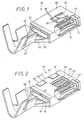
- the metallically conductive core of a die part 10 of a flat plug connection is shown, which still includes an insulation housing (not shown in more detail).
- the contact member comprises an extremely flat knife blade 21 with a full rectangular cross-section, which is why this member will be referred to as "knife contact member 20" for short.
- the knife blade 21 comprises a one-piece, customary connection area 22 for the conductor (not shown in more detail), which in the present case includes conductor wire claws 23 and conductor insulation claws 24.
- the knife blade 21 is characterized by upper and lower blade surfaces 25, which are connected on both sides by extremely flat surface zones, which will be referred to as "knife edge 26" in the following.
- the tip 27 of the knife blade 21 is sharpened for a good introduction.
- the entire knife contact element is designed as a shaped sheet metal body, the knife blade 21 of which is produced by folding the sheet metal into a compressed double position.
- the conductive member 10 of the die part shown in its assembled state in FIG. 1 comprises three components, the appearance of which results from the diagrammatic representation of FIG. 2, the structure of which is detailed in FIGS. 4 to 8 of the first component, 9 to 12 of the second component and 13 to 16 of the third component.
- the innermost component of this die part 10 consists of a socket designed as a rectangular tube 11 for receiving the aforementioned knife blade 21 from the male part 20.
- the sheet material 12 is cut through in a flat blank resulting from FIG 7 shaped, which has two broad sides 14 on the long rectangular webs and its two narrow sides 15 on the short rectangular webs.
- the longitudinal slots 13 extend over a substantial length of the rectangular tube and between them a family of longitudinal parallel webs 16 are formed, each having a V-shaped longitudinal profile through a transverse kink 17 and 17 'and thereby with their V-bend inside 18 Rectangular tube 11 are directed. This creates contact webs 16 which surround the knife blade 21 of the coupled male part 20 on all sides.
- the cage 19 On the broad sides 14 of the cage 19 there are basically two groups of contact webs 16, which have an eccentrically arranged kink apex 17, 17 ', but are mirror images of one another in adjacent webs.
- the located on the narrow side 15 of the cage 19 contact web 16 has an approximately in the longitudinal center seated kink apex 17 '', which is why both V-legs are of equal length and therefore there is a shorter offset distance 37 ⁇ of the kink 17 ⁇ , in the cage 19 .
- the individual contact webs 16 are deformed one after the other during the coupling process, which is why only a small push-on force occurs in each case with a time delay.
- the webs 16 also have such a long web length and such a small web width and such a flat kink that only a relatively small deformation force is required in any case for their deformation.
- the longitudinal joint 31 which arises in the case of the described bending of the sheet material 12 in the rectangular tube 11 is located, as shown in FIGS. 2 and 7, on one broad side 14 of the rectangular profile.
- the position of the fold lines 30 in the sheet metal material 12 is indicated by dash-dotted lines in FIG. 8.
- a funnel-shaped flange 32 At the outer end of the cage 19 is a funnel-shaped flange 32, which is interrupted for easier bending in the area of the folding lines 30 due to cutouts 33 in the sheet metal material 12 and during later assembly serves as a stop for the next component 40 of the die part 10.
- a locking opening 34 in one broad profile side 14 also serves to secure the mounting position.
- This next component consists of a two-part base member 40, which, as shown in FIGS. 2 and 9 to 12, forms in one piece from its sheet metal material 42 a box-shaped quiver 41 at one end and a usual connection area 43 for the conductor with corresponding claws.
- the box-shaped quiver 41 consists of a rectangular profile 44 which results from FIG. 10 and which is designed to closely match the dimensions of the cage 19, which in this case forms an insert to be positioned in the quiver interior 48 in the case of assembly.
- the cage 19 is inserted from the free end 45 into the base member 40 until finally the aforementioned funnel flange 32 strikes there.
- the mutual mounting position of the two parts 19, 40 can additionally or additionally also be achieved by welded connections, which are expediently carried out in the region of the longitudinal joint 49 or 31. Welds, mainly if they extend over a larger joint length, then create an annular closed rectangular profile, which contributes to the stiffening.
- the quiver 41 is finally provided on its outer broad sides with projecting latching hooks 47, 38, which serve to position and secure the position of a third component 50 of the die part 10 according to the invention, the appearance of which is described in more detail in FIGS. 13 to 16.
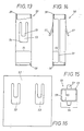
- This third component consists of a protective sleeve 50 which has the rectangular profile 51 shown in FIG. 15 and is made of a specific material with high strength, such as steel sheet 52, which in the first phase of its shaping is the stamped sheet metal shown in FIG. 16.
- a protective sleeve 50 which has the rectangular profile 51 shown in FIG. 15 and is made of a specific material with high strength, such as steel sheet 52, which in the first phase of its shaping is the stamped sheet metal shown in FIG. 16.
- This is related to the other sheet web, which is moved from station to station in strip form, of course, via a projection 36 indicated in FIG.
- the sheet material 12 in the rectangular tube quiver 19 is of a different type and consists of a material with a high spring constant, which satisfies the elastic properties of the contact webs 16.
- the sheet metal sheet 42 of the base part 40 on the other hand, consists of a material with particularly good conductivity, which is why a high copper content in the sheet metal alloy is desirable here.
- the steel sheet 52 is already provided with two windows 53 in the die-cut of FIG. 6, in which, in the later shaping, outwardly bent retaining tongues 57 are cut, which are used for the later assembly of the insulation housing of this die part 10 mentioned at the beginning.
- the rectangular profile 51 is again created by folding the steel sheet 52 on parallel lines that determine the profile corners, the analog longitudinal joint 59 that arises here being located on one profile narrow side 55, while the aforementioned windows 53 with the retaining tongues 57 on both profile broad sides 54 are positioned.
- the protective sleeve 50 has a profile size 51 which can encase the box-shaped case 41 of the base member 40 in a close fit.
- the aforementioned latching hooks 47 and 38 serve to mutually secure the position of these two components.
- the inner latching hook 47 serves as an end stop for the inner end 58 of the protective sleeve 50.
- the outer latching hooks 38 move into the window 53 located on the broad sides 54 mentioned and engage behind the inner window edge 56 shown in FIG. 13.
- the length of the protective sleeve 50 is selected to match the quiver 41; in particular, the above-mentioned end face 45 with the funnel flange 32 of the cage 19 inserted there lies after the position secured by the latching hooks 38, 47 flush with the outer end 39 of the protective sleeve.
- the mutual position between the protective sleeve 50 and the base member 40 can alternatively or additionally be determined by welding, in particular laser welding. Welded connections are expediently carried out again in the longitudinal joint 59 of the rectangular profile 51 and can also serve to create a rectangular profile 51 which is closed in a ring-shaped manner.
- a locking projection extends through the window 53 ⁇ and the opening 60 and thereby fixes the position of these parts in the die part 10 ⁇ and locks the die part with the associated insulation housing.
- Another specialty of FIG. 3 is finally that at least in the protective sleeve 50 ⁇ , the resulting joint 59 ⁇ runs like a labyrinth and extends over both the broad profile side 54 and the narrow profile side 55. This crenellated labyrinth course creates upper and lower fingers 61, 62, which engage in one another and extend from one profile side 54 to the other 55 or vice versa. This makes the rectangular profile of the protective sleeve 50hül more rigid and improves the mounting position with the other components of this die part 10 ⁇ .
- the design of the die part shown in FIG. 1 has the same appearance as the components of a modification described in FIGS. 4 to 16. These only differ in the dimensioning of the profile widths; the rectangular profile shown in FIGS. 1 and 2 has a larger dimension Broadside 54 and therefore belongs to an analog flat connector of a different size, which of course also includes a knife contact member with a correspondingly widened blade surface 25. Accordingly, a larger number of contact webs 16 is also possible there, as has already been described. 4 to 6, the cage 19 can be provided on its broad side 14 provided with the longitudinal joint 31 with a projection 63, the top of which cooperates with the inner wall surface of the quiver 41 from the base member 40 when the assembly is required. In the exemplary embodiments of FIGS. 1 to 3, the longitudinal joints 31, 49 of the cage 19 and the quiver 41 are in alignment with one another, which is favorable for the welded connection mentioned, for example by laser welding.
Landscapes
- Connector Housings Or Holding Contact Members (AREA)
- Manufacturing Of Electrical Connectors (AREA)
- Connections Effected By Soldering, Adhesion, Or Permanent Deformation (AREA)
Applications Claiming Priority (2)
| Application Number | Priority Date | Filing Date | Title |
|---|---|---|---|
| DE3817803A DE3817803C3 (de) | 1988-05-26 | 1988-05-26 | Elektrische Flachsteckverbindung |
| DE3817803 | 1988-05-26 |
Publications (3)
| Publication Number | Publication Date |
|---|---|
| EP0343550A2 true EP0343550A2 (fr) | 1989-11-29 |
| EP0343550A3 EP0343550A3 (en) | 1990-11-28 |
| EP0343550B1 EP0343550B1 (fr) | 1995-04-19 |
Family
ID=6355114
Family Applications (1)
| Application Number | Title | Priority Date | Filing Date |
|---|---|---|---|
| EP89109140A Expired - Lifetime EP0343550B1 (fr) | 1988-05-26 | 1989-05-20 | Prise électrique pour contacts plats |
Country Status (5)
| Country | Link |
|---|---|
| US (1) | US4934965A (fr) |
| EP (1) | EP0343550B1 (fr) |
| DE (2) | DE3817803C3 (fr) |
| ES (1) | ES2072873T3 (fr) |
| PT (1) | PT90144B (fr) |
Cited By (7)
| Publication number | Priority date | Publication date | Assignee | Title |
|---|---|---|---|---|
| EP0487906A3 (en) * | 1990-11-29 | 1993-04-14 | Molex Incorporated | Shrouded electrical connector |
| FR2707431A1 (fr) * | 1993-07-06 | 1995-01-13 | Briffe Roger | Connecteur électrique femelle à fiabilité améliorée. |
| WO2005046002A1 (fr) * | 2003-11-03 | 2005-05-19 | Intedis Gmbh & Co. Kg | Fiche femelle plate |
| EP1340290B1 (fr) * | 2000-12-07 | 2007-04-18 | Fci | Contact femelle a cage avec un module porte-lames |
| DE102010024525A1 (de) * | 2010-06-21 | 2011-12-22 | Fritz Stepper Gmbh & Co. Kg | Elektrischer Buchsenkontakt |
| CN104364970A (zh) * | 2012-06-13 | 2015-02-18 | 矢崎总业株式会社 | 连接器端子 |
| DE112014003160B4 (de) | 2013-07-05 | 2026-04-16 | Yazaki Corporation | Weiblicher Anschluss |
Families Citing this family (54)
| Publication number | Priority date | Publication date | Assignee | Title |
|---|---|---|---|---|
| DE4131470A1 (de) * | 1991-09-21 | 1993-04-01 | Kostal Leopold Gmbh & Co Kg | Elektrisches steckkontaktteil |
| USD346360S (en) | 1992-02-20 | 1994-04-26 | Richard Kiegler | Side plug-in outlet |
| US5269699A (en) * | 1992-06-09 | 1993-12-14 | Molex Incorporated | Lockable electrical connector assembly |
| JP2723432B2 (ja) * | 1992-11-12 | 1998-03-09 | 矢崎総業株式会社 | 雌型端子金具 |
| US5342226A (en) * | 1993-06-21 | 1994-08-30 | Electro-Wire Products, Inc. | Female blade terminal |
| FR2711849A1 (fr) * | 1993-10-27 | 1995-05-05 | Amp France | Borne électrique à contact à déplacement d'isolant et ressort de renfort. |
| DE4439105C1 (de) | 1994-11-02 | 1996-04-25 | Kostal Leopold Gmbh & Co Kg | Elektrische Steckverbindung |
| DE19518828C2 (de) * | 1995-05-23 | 2002-03-28 | Delphi Automotive Systems Gmbh | Flachsteckhülse |
| US5890936A (en) * | 1996-10-15 | 1999-04-06 | Ut Automotive Dearborn, Inc. | Electrical terminal |
| JP3030379B2 (ja) * | 1996-10-22 | 2000-04-10 | 株式会社テーアンテー | スイッチの接続構造 |
| DE19835020C2 (de) * | 1998-08-03 | 2001-02-08 | Tyco Electronics Logistics Ag | Buchsenkontakt |
| DE19841232C2 (de) * | 1998-09-09 | 2001-02-15 | Framatome Connectors Int | Buchsenkontakt für elektrische Stecker |
| DE10013840C2 (de) * | 2000-03-21 | 2003-05-08 | Grote & Hartmann | Elektrisches Kontaktelement |
| JP2001307808A (ja) * | 2000-04-18 | 2001-11-02 | Ryosei Electro-Circuit Systems Ltd | 接続端子 |
| US6672911B2 (en) * | 2000-09-15 | 2004-01-06 | Alcoa Fujikura Limited | Electrical terminal socket assembly including 90 angled and sealed connectors |
| US20030060090A1 (en) * | 2001-09-21 | 2003-03-27 | Allgood Christopher L. | High current automotive electrical connector and terminal |
| JP3415133B1 (ja) * | 2002-06-06 | 2003-06-09 | 住友電装株式会社 | 端子金具及びコネクタ |
| DE10248809A1 (de) * | 2002-10-19 | 2004-04-29 | Robert Bosch Gmbh | Elektrischer Steckverbinder in der Ausgestaltung eines Buchsenkontakts mit spezieller Lamellengestaltung |
| DE10252840A1 (de) * | 2002-11-13 | 2004-05-27 | Delphi Technologies, Inc., Troy | Anschlusselement |
| US20050059303A1 (en) * | 2003-08-27 | 2005-03-17 | Panella Augusto P. | Dual plane power contact |
| CN100566037C (zh) * | 2004-07-12 | 2009-12-02 | 安普泰科电子有限公司 | 插座端子 |
| JP4514645B2 (ja) * | 2004-07-12 | 2010-07-28 | タイコエレクトロニクスジャパン合同会社 | 雌型端子 |
| EP1622226A1 (fr) * | 2004-07-30 | 2006-02-01 | Lisa Dräxlmaier GmbH | Interface à courant fort pour véhicules automobiles |
| DE102004052712B4 (de) | 2004-10-30 | 2014-09-25 | Erni Electronics Gmbh | Einteilige, zweischenklige Kontaktfeder für Miniatur-Steckverbindungen |
| DE102005017988B3 (de) * | 2005-04-19 | 2006-11-16 | Tyco Electronics Amp Gmbh | Elektrische Kontakthülse |
| DE102006009357B8 (de) * | 2006-03-01 | 2008-02-14 | Tyco Electronics Amp Gmbh | Elektrische Flachsteckhülse |
| DE102006062704B4 (de) * | 2006-03-01 | 2008-12-04 | Tyco Electronics Amp Gmbh | Elektrische Flachsteckhülse |
| DE102006053152B3 (de) * | 2006-11-10 | 2008-04-10 | Tyco Electronics Amp Gmbh | Elektrischer Buchsenkontakt |
| DE102007016070A1 (de) * | 2007-04-03 | 2008-10-09 | Lear Corp., Southfield | Elektrische Anschlussanordnung und Verfahren zum Nutzen der elektrischen Anschlussanordnung |
| DE102007049055B3 (de) * | 2007-10-11 | 2009-03-26 | Tyco Electronics Amp Gmbh | Vibrationsdämpfendes Kontaktelement |
| US8668531B2 (en) * | 2009-07-03 | 2014-03-11 | Yazaki Corporation | Terminal |
| JP5381492B2 (ja) * | 2009-08-19 | 2014-01-08 | 住友電装株式会社 | 雌端子金具 |
| DE102009038092B3 (de) * | 2009-08-19 | 2010-12-09 | Amphenol-Tuchel Electronics Gmbh | Buchsenkontaktelement |
| KR101598633B1 (ko) * | 2009-11-11 | 2016-02-29 | 타이코에이엠피 주식회사 | 커넥터용 단자 |
| DE202010003555U1 (de) * | 2010-03-16 | 2010-07-08 | Rosenberger Hochfrequenztechnik Gmbh & Co. Kg | Hochstromsteckverbinder |
| DE202010003649U1 (de) * | 2010-03-16 | 2010-07-15 | Rosenberger Hochfrequenztechnik Gmbh & Co. Kg | Hochstromsteckverbinder |
| DE102010028672B4 (de) * | 2010-05-06 | 2015-07-02 | Tyco Electronics Amp Gmbh | Steckverbindung mit Spielausgleichseinrichtung |
| US8628335B1 (en) * | 2012-12-07 | 2014-01-14 | Tyco Electronics Corporation | Power terminal connector |
| US9548553B2 (en) * | 2013-03-15 | 2017-01-17 | Lear Corporation | Terminal with front end protection |
| CN104505676A (zh) * | 2014-12-16 | 2015-04-08 | 莫胜林 | 一种强电插接件及应用该插接件的电源插座 |
| CN107134674B (zh) * | 2016-02-29 | 2021-04-27 | 泰科电子(上海)有限公司 | 导电连接件及连接组件 |
| US10965333B2 (en) | 2016-07-26 | 2021-03-30 | Laird Technologies, Inc. | Thermal management assemblies suitable for use with transceivers and other devices |
| US10389397B2 (en) * | 2016-07-26 | 2019-08-20 | Laird Technologies, Inc. | Small form-factor pluggable (SFP) transceivers |
| WO2018063928A1 (fr) * | 2016-09-30 | 2018-04-05 | Molex, Llc | Connecteur à douille |
| CN106877095A (zh) * | 2017-03-14 | 2017-06-20 | 深圳尼索科连接技术有限公司 | 插套式电连接装置 |
| CN109149207B (zh) * | 2017-06-28 | 2020-10-30 | 拓自达电线株式会社 | 连接器、电线组件、以及医疗设备用传感器 |
| CN109149145B (zh) | 2017-06-28 | 2020-12-08 | 拓自达电线株式会社 | 压接端子、带压接端子的电线以及医疗设备用传感器 |
| DE102017220185A1 (de) * | 2017-11-13 | 2019-05-16 | Te Connectivity Germany Gmbh | Buchsenkontakt |
| US10193247B1 (en) * | 2017-11-14 | 2019-01-29 | Lear Corporation | Electrical contact spring with extensions |
| DE102018214206A1 (de) * | 2018-08-22 | 2020-02-27 | Te Connectivity Germany Gmbh | Buchsenkontaktanordnung, Buchsenkontakt und Steckkontaktanordnung |
| US11862882B2 (en) | 2021-05-26 | 2024-01-02 | J.S.T. Corporation | Tubular high current female terminal |
| JP2024105976A (ja) * | 2023-01-26 | 2024-08-07 | 株式会社オートネットワーク技術研究所 | 雌端子および端子ユニット |
| JP2025080355A (ja) * | 2023-11-14 | 2025-05-26 | 株式会社オートネットワーク技術研究所 | 雌端子および端子ユニット |
| JP2025080856A (ja) * | 2023-11-15 | 2025-05-27 | 株式会社オートネットワーク技術研究所 | 雌端子および端子ユニット |
Family Cites Families (12)
| Publication number | Priority date | Publication date | Assignee | Title |
|---|---|---|---|---|
| US2701350A (en) * | 1952-10-18 | 1955-02-01 | Soreng Products Corp | Separable electrical connector |
| US3370265A (en) * | 1966-05-09 | 1968-02-20 | Berg Electronics Inc | Electrical connector |
| DE1790063A1 (de) * | 1968-09-04 | 1971-12-02 | Calor Emag Elektrozitaets Ag | Elektrische Kontaktanordnung |
| US4002400A (en) * | 1975-08-01 | 1977-01-11 | E. I. Du Pont De Nemours And Company | Electrical connector |
| US4448477A (en) * | 1982-03-19 | 1984-05-15 | General Motors Corporation | Electric socket terminal |
| NL8202668A (nl) * | 1982-07-02 | 1984-02-01 | Philips Nv | Elektrisch kontaktorgaan. |
| DE3244939C1 (de) * | 1982-12-04 | 1984-03-29 | Kabelwerke Reinshagen Gmbh, 5600 Wuppertal | Verriegelbare elektrische Flachsteckbuchse und damit versehener elektrischer Verbinder |
| DE3248078C2 (de) * | 1982-12-24 | 1986-03-27 | Grote & Hartmann Gmbh & Co Kg, 5600 Wuppertal | Doppelflachfederkontakt mit Überfeder |
| DE3502633C1 (de) * | 1985-01-26 | 1986-04-30 | Kabelwerke Reinshagen Gmbh, 5600 Wuppertal | Elektrischer Doppelflachfederkontakt |
| DE8508964U1 (de) * | 1985-03-26 | 1986-12-18 | Grote & Hartmann Gmbh & Co Kg, 5600 Wuppertal | Kastenfeder |
| DE3531845C2 (de) * | 1985-09-06 | 1994-05-26 | Daut & Rietz Trw | Kontaktteil, geformt als Buchsen- oder Steckerteil zum Einsetzen in Buchsen- oder Steckergehäusen |
| DE3625384A1 (de) * | 1986-07-26 | 1988-02-04 | Reinshagen Kabelwerk Gmbh | Elektrische steckverbindung |
-
1988
- 1988-05-26 DE DE3817803A patent/DE3817803C3/de not_active Expired - Fee Related
-
1989
- 1989-03-29 PT PT90144A patent/PT90144B/pt not_active IP Right Cessation
- 1989-05-20 DE DE58909181T patent/DE58909181D1/de not_active Expired - Lifetime
- 1989-05-20 ES ES89109140T patent/ES2072873T3/es not_active Expired - Lifetime
- 1989-05-20 EP EP89109140A patent/EP0343550B1/fr not_active Expired - Lifetime
- 1989-05-25 US US07/357,178 patent/US4934965A/en not_active Expired - Lifetime
Cited By (8)
| Publication number | Priority date | Publication date | Assignee | Title |
|---|---|---|---|---|
| EP0487906A3 (en) * | 1990-11-29 | 1993-04-14 | Molex Incorporated | Shrouded electrical connector |
| FR2707431A1 (fr) * | 1993-07-06 | 1995-01-13 | Briffe Roger | Connecteur électrique femelle à fiabilité améliorée. |
| EP1340290B1 (fr) * | 2000-12-07 | 2007-04-18 | Fci | Contact femelle a cage avec un module porte-lames |
| WO2005046002A1 (fr) * | 2003-11-03 | 2005-05-19 | Intedis Gmbh & Co. Kg | Fiche femelle plate |
| DE102010024525A1 (de) * | 2010-06-21 | 2011-12-22 | Fritz Stepper Gmbh & Co. Kg | Elektrischer Buchsenkontakt |
| DE102010024525B4 (de) * | 2010-06-21 | 2013-10-24 | Fritz Stepper Gmbh & Co. Kg | Elektrischer Buchsenkontakt |
| CN104364970A (zh) * | 2012-06-13 | 2015-02-18 | 矢崎总业株式会社 | 连接器端子 |
| DE112014003160B4 (de) | 2013-07-05 | 2026-04-16 | Yazaki Corporation | Weiblicher Anschluss |
Also Published As
| Publication number | Publication date |
|---|---|
| DE58909181D1 (de) | 1995-05-24 |
| PT90144B (pt) | 1994-05-31 |
| EP0343550B1 (fr) | 1995-04-19 |
| EP0343550A3 (en) | 1990-11-28 |
| DE3817803C2 (fr) | 1991-07-25 |
| ES2072873T3 (es) | 1995-08-01 |
| DE3817803A1 (de) | 1989-11-30 |
| DE3817803C3 (de) | 1995-04-20 |
| PT90144A (pt) | 1989-11-30 |
| US4934965A (en) | 1990-06-19 |
Similar Documents
| Publication | Publication Date | Title |
|---|---|---|
| EP0343550B1 (fr) | Prise électrique pour contacts plats | |
| DE69228392T2 (de) | Elektrischer Kontakt | |
| EP1103088B1 (fr) | Contact de douille | |
| DE69417780T2 (de) | Zweiteiliges Abschirmgehäuse für einen Verbinder | |
| DE102014009207B4 (de) | Verfahren zur montage einer elektrischen anschlussanordnung | |
| EP2115820B1 (fr) | Élément de contact et utilisation d'un tel élément de contact dans une connexion par enfichage | |
| EP0510134B1 (fr) | Fiche a contact plat | |
| EP1503457B1 (fr) | Connecteur femelle pour fiche plate | |
| DE102016221351A1 (de) | Flachkontaktbuchse mit Ausleger | |
| DE8120543U1 (de) | Elektrischer Verbinder zum Anschließen an Vielleiter-Flachkabel | |
| DE69320680T2 (de) | Elektrische Anschlussbuchse | |
| DE9106773U1 (de) | Elektrischer Steckkontakt | |
| EP0196367A1 (fr) | Ressort en forme de boîtier | |
| DE10318182B4 (de) | Steckkontakt und Verfahren zum Ausbilden desselben | |
| DE10313921B4 (de) | Buchsen-Anschlußpaßstück | |
| DE112012002503T5 (de) | Anschlusselement | |
| DE2752093A1 (de) | Anschlussklemmen | |
| DE7915035U1 (de) | Elektrische Anschlußvorrichtung | |
| DE19855824A1 (de) | Verbindungserkennungsmechanismus für eine Steckverbindung aus einem Stecker und einer Steckbuchse | |
| EP0738028A1 (fr) | Fiche plate | |
| DE10202292A1 (de) | Anschlußpaßstück | |
| DE3418249A1 (de) | Flachsteckerbuchsenklemme | |
| DE69505925T2 (de) | Elektrische Kontaktbuchse | |
| EP1819019A1 (fr) | Fiche mâle et fiche femelle de prise électrique et agencement de prise électrique doté d'une telle fiche mâle et d'une telle fiche femelle | |
| DE3600456C2 (fr) |
Legal Events
| Date | Code | Title | Description |
|---|---|---|---|
| PUAI | Public reference made under article 153(3) epc to a published international application that has entered the european phase |
Free format text: ORIGINAL CODE: 0009012 |
|
| AK | Designated contracting states |
Kind code of ref document: A2 Designated state(s): BE DE ES FR GB IT SE |
|
| PUAL | Search report despatched |
Free format text: ORIGINAL CODE: 0009013 |
|
| AK | Designated contracting states |
Kind code of ref document: A3 Designated state(s): BE DE ES FR GB IT SE |
|
| 17P | Request for examination filed |
Effective date: 19901214 |
|
| 17Q | First examination report despatched |
Effective date: 19930709 |
|
| GRAA | (expected) grant |
Free format text: ORIGINAL CODE: 0009210 |
|
| AK | Designated contracting states |
Kind code of ref document: B1 Designated state(s): BE DE ES FR GB IT SE |
|
| PG25 | Lapsed in a contracting state [announced via postgrant information from national office to epo] |
Ref country code: BE Effective date: 19950419 |
|
| ITF | It: translation for a ep patent filed | ||
| REF | Corresponds to: |
Ref document number: 58909181 Country of ref document: DE Date of ref document: 19950524 |
|
| GBT | Gb: translation of ep patent filed (gb section 77(6)(a)/1977) |
Effective date: 19950427 |
|
| PG25 | Lapsed in a contracting state [announced via postgrant information from national office to epo] |
Ref country code: SE Effective date: 19950719 |
|
| REG | Reference to a national code |
Ref country code: ES Ref legal event code: FG2A Ref document number: 2072873 Country of ref document: ES Kind code of ref document: T3 |
|
| ET | Fr: translation filed | ||
| RAP2 | Party data changed (patent owner data changed or rights of a patent transferred) |
Owner name: DELPHI AUTOMOTIVE SYSTEMS DEUTSCHLAND GMBH |
|
| PLBE | No opposition filed within time limit |
Free format text: ORIGINAL CODE: 0009261 |
|
| STAA | Information on the status of an ep patent application or granted ep patent |
Free format text: STATUS: NO OPPOSITION FILED WITHIN TIME LIMIT |
|
| REG | Reference to a national code |
Ref country code: FR Ref legal event code: CD |
|
| 26N | No opposition filed | ||
| PGFP | Annual fee paid to national office [announced via postgrant information from national office to epo] |
Ref country code: GB Payment date: 20010417 Year of fee payment: 13 |
|
| PGFP | Annual fee paid to national office [announced via postgrant information from national office to epo] |
Ref country code: ES Payment date: 20010528 Year of fee payment: 13 |
|
| REG | Reference to a national code |
Ref country code: GB Ref legal event code: IF02 |
|
| PG25 | Lapsed in a contracting state [announced via postgrant information from national office to epo] |
Ref country code: GB Free format text: LAPSE BECAUSE OF NON-PAYMENT OF DUE FEES Effective date: 20020520 |
|
| PG25 | Lapsed in a contracting state [announced via postgrant information from national office to epo] |
Ref country code: ES Free format text: LAPSE BECAUSE OF NON-PAYMENT OF DUE FEES Effective date: 20020521 |
|
| GBPC | Gb: european patent ceased through non-payment of renewal fee |
Effective date: 20020520 |
|
| REG | Reference to a national code |
Ref country code: ES Ref legal event code: FD2A Effective date: 20030611 |
|
| PGFP | Annual fee paid to national office [announced via postgrant information from national office to epo] |
Ref country code: DE Payment date: 20080529 Year of fee payment: 20 |
|
| PGFP | Annual fee paid to national office [announced via postgrant information from national office to epo] |
Ref country code: IT Payment date: 20080527 Year of fee payment: 20 |
|
| PGFP | Annual fee paid to national office [announced via postgrant information from national office to epo] |
Ref country code: FR Payment date: 20080514 Year of fee payment: 20 |