EP0343550A2 - Electrical flat plug socket - Google Patents
Electrical flat plug socket Download PDFInfo
- Publication number
- EP0343550A2 EP0343550A2 EP89109140A EP89109140A EP0343550A2 EP 0343550 A2 EP0343550 A2 EP 0343550A2 EP 89109140 A EP89109140 A EP 89109140A EP 89109140 A EP89109140 A EP 89109140A EP 0343550 A2 EP0343550 A2 EP 0343550A2
- Authority
- EP
- European Patent Office
- Prior art keywords
- cage
- flat
- contact
- quiver
- protective sleeve
- Prior art date
- Legal status (The legal status is an assumption and is not a legal conclusion. Google has not performed a legal analysis and makes no representation as to the accuracy of the status listed.)
- Granted
Links
Images


Classifications
-
- H—ELECTRICITY
- H01—ELECTRIC ELEMENTS
- H01R—ELECTRICALLY-CONDUCTIVE CONNECTIONS; STRUCTURAL ASSOCIATIONS OF A PLURALITY OF MUTUALLY-INSULATED ELECTRICAL CONNECTING ELEMENTS; COUPLING DEVICES; CURRENT COLLECTORS
- H01R13/00—Details of coupling devices of the kinds covered by groups H01R12/70 or H01R24/00 - H01R33/00
- H01R13/02—Contact members
- H01R13/10—Sockets for co-operation with pins or blades
- H01R13/11—Resilient sockets
- H01R13/113—Resilient sockets co-operating with pins or blades having a rectangular transverse section
-
- H—ELECTRICITY
- H01—ELECTRIC ELEMENTS
- H01R—ELECTRICALLY-CONDUCTIVE CONNECTIONS; STRUCTURAL ASSOCIATIONS OF A PLURALITY OF MUTUALLY-INSULATED ELECTRICAL CONNECTING ELEMENTS; COUPLING DEVICES; CURRENT COLLECTORS
- H01R13/00—Details of coupling devices of the kinds covered by groups H01R12/70 or H01R24/00 - H01R33/00
- H01R13/40—Securing contact members in or to a base or case; Insulating of contact members
- H01R13/42—Securing in a demountable manner
- H01R13/428—Securing in a demountable manner by resilient locking means on the contact members; by locking means on resilient contact members
- H01R13/432—Securing in a demountable manner by resilient locking means on the contact members; by locking means on resilient contact members by stamped-out resilient tongue snapping behind shoulder in base or case
Definitions
- the invention is directed to a flat plug connection of the type specified in the preamble of claim 1.
- the socket member has a C-shaped flat profile, the profile leg ends of which are rolled up and in the case of coupling with one blade surface contact the knife contact member on the male part, while the opposite blade surface is spring-loaded by a tongue formed on the C-profile web and bent back into the profile interior.
- the C-legs merge with longitudinal edges into the C-web connecting them and form a receiving channel containing the tongue, which only touches the knife contact element in places.
- the areas of the C-leg located on the narrow sides of the flat profile do not come into contact with the knife edges of the male part.
- In order to improve the contact one had to rely on a high spring load to be exerted by the tongue, which, however, had the disadvantage of requiring a high plug-on force on the die part when the knife contact element was engaged.
- the invention has for its object to develop a space-saving tab connector due to the knife contact member of the type mentioned in the preamble of claim 1, which on the one hand has good contacting and on the other hand manages with low insertion forces during the coupling process.
- the invention has made it possible to reconcile these two apparently contradicting demands for good contact and low attachment forces and is characterized by the following special features.
- the socket member is equipped as a rectangular tube with webs created by longitudinal slots on all tube sides, contact webs also come to rest on the rectangular narrow sides, which come into contact with the knife edges of the male part in the event of a coupling.
- the socket member is thus designed on all sides as a cage, the cage webs of which have single or multiple kinks or arches and thus run in a V or W shape.
- the kink or arch apex produced in this way springs on all sides against the knife contact element coupled into the interior of the cage and is effective in contact. This gives contact points distributed over the entire circumference of the profile, which summatively produce a large contact area.
- Each kinked or curved contact web is under its own spring load due to its V- or W-shape, which is sufficient for good contacting, but due to the very slim, long web shape requires surprisingly low attachment forces during the coupling process to deform it.
- the course of the kink or curve is leveled in the contact web and contacts with its apex. Coupling is thus easy and you get a good electrical transition even for higher electrical currents.
- a single kink in each contact web, which establishes a V-shaped web profile, is particularly advantageous.
- plug connectors DE-PS 35 02 633
- the socket member is designed as a full rectangular tube, but this does not have a cage structure, but on the broad sides molded, mutually curved spring arm pairs, on which a pair of reinforcing springs presses, in a corresponding manner Is integrally formed on a reinforcing sleeve to be pushed over the socket member.
- the contact webs located on the narrow sides of the cage can, as proposed in claim 4, be designed symmetrically because they are then deformed in time between the aforementioned asymmetrical kinks or bends of the other contact webs when coupling.
- the simplest version of the die part can be formed in one piece.
- This sheet material is, according to claim 8, angled and folded until it creates the cage designed as a rectangular tube, quiver or protective sleeve with a longitudinal joint.
- These longitudinal joints will be placed, mainly between the quiver and the protective sleeve, on different sides of the rectangular tube, the narrow side being particularly suitable for the protective sleeve, because the holding hooks for the insulation housing can be positioned more favorably on the broad side .
- welds can be used, preferably by the action of a laser be generated.
- the location of these welds is recommended, according to claim 13, the longitudinal joint, because this does not result in an annoying projection.
- Such welds can finally, according to claim 14, create a closed ring profile in the rectangular tube, which improves its shape, which is particularly interesting for the protective sleeve.
- an insertion funnel provided at the front end of the rectangular tube cage can also be used, which is stop-effective with the quiver of the base member.
- the strength could finally, according to claim 15, also be increased without welding if the longitudinal joint of the sheet material folded into a rectangular tube was made to maze like a labyrinth between two adjacent sides of the rectangle, thus creating mutually interdigitated fingers in the tube wall that extend over the edge of the rectangle.
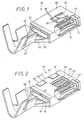
- the metallically conductive core of a die part 10 of a flat plug connection is shown, which still includes an insulation housing (not shown in more detail).
- the contact member comprises an extremely flat knife blade 21 with a full rectangular cross-section, which is why this member will be referred to as "knife contact member 20" for short.
- the knife blade 21 comprises a one-piece, customary connection area 22 for the conductor (not shown in more detail), which in the present case includes conductor wire claws 23 and conductor insulation claws 24.
- the knife blade 21 is characterized by upper and lower blade surfaces 25, which are connected on both sides by extremely flat surface zones, which will be referred to as "knife edge 26" in the following.
- the tip 27 of the knife blade 21 is sharpened for a good introduction.
- the entire knife contact element is designed as a shaped sheet metal body, the knife blade 21 of which is produced by folding the sheet metal into a compressed double position.
- the conductive member 10 of the die part shown in its assembled state in FIG. 1 comprises three components, the appearance of which results from the diagrammatic representation of FIG. 2, the structure of which is detailed in FIGS. 4 to 8 of the first component, 9 to 12 of the second component and 13 to 16 of the third component.
- the innermost component of this die part 10 consists of a socket designed as a rectangular tube 11 for receiving the aforementioned knife blade 21 from the male part 20.
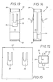
- the sheet material 12 is cut through in a flat blank resulting from FIG 7 shaped, which has two broad sides 14 on the long rectangular webs and its two narrow sides 15 on the short rectangular webs.
- the longitudinal slots 13 extend over a substantial length of the rectangular tube and between them a family of longitudinal parallel webs 16 are formed, each having a V-shaped longitudinal profile through a transverse kink 17 and 17 'and thereby with their V-bend inside 18 Rectangular tube 11 are directed. This creates contact webs 16 which surround the knife blade 21 of the coupled male part 20 on all sides.
- the cage 19 On the broad sides 14 of the cage 19 there are basically two groups of contact webs 16, which have an eccentrically arranged kink apex 17, 17 ', but are mirror images of one another in adjacent webs.
- the located on the narrow side 15 of the cage 19 contact web 16 has an approximately in the longitudinal center seated kink apex 17 '', which is why both V-legs are of equal length and therefore there is a shorter offset distance 37 ⁇ of the kink 17 ⁇ , in the cage 19 .
- the individual contact webs 16 are deformed one after the other during the coupling process, which is why only a small push-on force occurs in each case with a time delay.
- the webs 16 also have such a long web length and such a small web width and such a flat kink that only a relatively small deformation force is required in any case for their deformation.
- the longitudinal joint 31 which arises in the case of the described bending of the sheet material 12 in the rectangular tube 11 is located, as shown in FIGS. 2 and 7, on one broad side 14 of the rectangular profile.
- the position of the fold lines 30 in the sheet metal material 12 is indicated by dash-dotted lines in FIG. 8.
- a funnel-shaped flange 32 At the outer end of the cage 19 is a funnel-shaped flange 32, which is interrupted for easier bending in the area of the folding lines 30 due to cutouts 33 in the sheet metal material 12 and during later assembly serves as a stop for the next component 40 of the die part 10.
- a locking opening 34 in one broad profile side 14 also serves to secure the mounting position.
- This next component consists of a two-part base member 40, which, as shown in FIGS. 2 and 9 to 12, forms in one piece from its sheet metal material 42 a box-shaped quiver 41 at one end and a usual connection area 43 for the conductor with corresponding claws.
- the box-shaped quiver 41 consists of a rectangular profile 44 which results from FIG. 10 and which is designed to closely match the dimensions of the cage 19, which in this case forms an insert to be positioned in the quiver interior 48 in the case of assembly.
- the cage 19 is inserted from the free end 45 into the base member 40 until finally the aforementioned funnel flange 32 strikes there.
- the mutual mounting position of the two parts 19, 40 can additionally or additionally also be achieved by welded connections, which are expediently carried out in the region of the longitudinal joint 49 or 31. Welds, mainly if they extend over a larger joint length, then create an annular closed rectangular profile, which contributes to the stiffening.
- the quiver 41 is finally provided on its outer broad sides with projecting latching hooks 47, 38, which serve to position and secure the position of a third component 50 of the die part 10 according to the invention, the appearance of which is described in more detail in FIGS. 13 to 16.
- This third component consists of a protective sleeve 50 which has the rectangular profile 51 shown in FIG. 15 and is made of a specific material with high strength, such as steel sheet 52, which in the first phase of its shaping is the stamped sheet metal shown in FIG. 16.
- a protective sleeve 50 which has the rectangular profile 51 shown in FIG. 15 and is made of a specific material with high strength, such as steel sheet 52, which in the first phase of its shaping is the stamped sheet metal shown in FIG. 16.
- This is related to the other sheet web, which is moved from station to station in strip form, of course, via a projection 36 indicated in FIG.
- the sheet material 12 in the rectangular tube quiver 19 is of a different type and consists of a material with a high spring constant, which satisfies the elastic properties of the contact webs 16.
- the sheet metal sheet 42 of the base part 40 on the other hand, consists of a material with particularly good conductivity, which is why a high copper content in the sheet metal alloy is desirable here.
- the steel sheet 52 is already provided with two windows 53 in the die-cut of FIG. 6, in which, in the later shaping, outwardly bent retaining tongues 57 are cut, which are used for the later assembly of the insulation housing of this die part 10 mentioned at the beginning.
- the rectangular profile 51 is again created by folding the steel sheet 52 on parallel lines that determine the profile corners, the analog longitudinal joint 59 that arises here being located on one profile narrow side 55, while the aforementioned windows 53 with the retaining tongues 57 on both profile broad sides 54 are positioned.
- the protective sleeve 50 has a profile size 51 which can encase the box-shaped case 41 of the base member 40 in a close fit.
- the aforementioned latching hooks 47 and 38 serve to mutually secure the position of these two components.
- the inner latching hook 47 serves as an end stop for the inner end 58 of the protective sleeve 50.
- the outer latching hooks 38 move into the window 53 located on the broad sides 54 mentioned and engage behind the inner window edge 56 shown in FIG. 13.
- the length of the protective sleeve 50 is selected to match the quiver 41; in particular, the above-mentioned end face 45 with the funnel flange 32 of the cage 19 inserted there lies after the position secured by the latching hooks 38, 47 flush with the outer end 39 of the protective sleeve.
- the mutual position between the protective sleeve 50 and the base member 40 can alternatively or additionally be determined by welding, in particular laser welding. Welded connections are expediently carried out again in the longitudinal joint 59 of the rectangular profile 51 and can also serve to create a rectangular profile 51 which is closed in a ring-shaped manner.
- a locking projection extends through the window 53 ⁇ and the opening 60 and thereby fixes the position of these parts in the die part 10 ⁇ and locks the die part with the associated insulation housing.
- Another specialty of FIG. 3 is finally that at least in the protective sleeve 50 ⁇ , the resulting joint 59 ⁇ runs like a labyrinth and extends over both the broad profile side 54 and the narrow profile side 55. This crenellated labyrinth course creates upper and lower fingers 61, 62, which engage in one another and extend from one profile side 54 to the other 55 or vice versa. This makes the rectangular profile of the protective sleeve 50hül more rigid and improves the mounting position with the other components of this die part 10 ⁇ .
- the design of the die part shown in FIG. 1 has the same appearance as the components of a modification described in FIGS. 4 to 16. These only differ in the dimensioning of the profile widths; the rectangular profile shown in FIGS. 1 and 2 has a larger dimension Broadside 54 and therefore belongs to an analog flat connector of a different size, which of course also includes a knife contact member with a correspondingly widened blade surface 25. Accordingly, a larger number of contact webs 16 is also possible there, as has already been described. 4 to 6, the cage 19 can be provided on its broad side 14 provided with the longitudinal joint 31 with a projection 63, the top of which cooperates with the inner wall surface of the quiver 41 from the base member 40 when the assembly is required. In the exemplary embodiments of FIGS. 1 to 3, the longitudinal joints 31, 49 of the cage 19 and the quiver 41 are in alignment with one another, which is favorable for the welded connection mentioned, for example by laser welding.
Landscapes
- Connector Housings Or Holding Contact Members (AREA)
- Manufacturing Of Electrical Connectors (AREA)
- Connections Effected By Soldering, Adhesion, Or Permanent Deformation (AREA)
Abstract
Bei einer elektrischen Steckverbindung umfaßt der Patrizenteil ein Messerkontaktglied, während der Matrizenteil ein mit kantigem Flachprofil ausgebildetes Buchsenglied besitzt. Um die Kontaktierungen zu verbessern und dabei dennoch die Aufsteckkräfte gering zu halten, wird vorgeschlagen, für das Buchsenglied ein volles Rechteckprofil zu verwenden, dessen Schmal- und Breitseite durch Längsschlitze in eine Schar paralleler Stege gegliedert sind, welche einen kantigen Käfig mit ins Käfiginnere geknickten oder gebogenen Kontaktstegen bilden. Dadurch kommen im Kupplungsfall die Knick- oder Bogenscheitel eines Kontaktstegs auch an der Messerkante des Patrizenteils zur Berührung. 
Description
Die Erfindung richtet sich auf eine Flachsteckverbindung der im Oberbegriff des Anspruches 1 angegebenen Art. Bei der bekannten Verbindung (DE-PS 32 44 939) besitzt das Buchsenglied ein C-förmiges Flachprofil, dessen Profilschenkel-Enden eingerollt sind und im Kupplungsfall mit der einen Klingenfläche des Messerkontaktglieds beim Patrizenteil kontaktieren, während die gegenüberliegende Klingenfläche von einer am C-Profilsteg angeformten, ins Profilinnere zurückgebogenen Zunge federbelastet wird. Die C-Schenkel gehen mit Längskanten in den sie verbindenden C-Steg über und formen einen die Zunge beinhaltenden Aufnahmekanal, der nur stellenweise das Messerkontaktglied berührt. So kommen die an den Schmalseiten des Flachprofils befindlichen Bereiche der C-Schenkel nicht mit den Messerkanten des Patrizenteils in Berührung. Um die Kontaktierung zu verbessern, war man auf eine hohe, von der Zunge auszuübende Federbelastung angewiesen, die aber den Nachteilhatten, beim Einkuppeln des Messerkontaktglieds eine hohe Aufsteckkraft beim Matrizenteil zu erfordern.The invention is directed to a flat plug connection of the type specified in the preamble of
Der Erfindung liegt die Aufgabe zugrunde, eine aufgrund des Messerkontaktglieds raumsparende Flachsteckverbindung der im Oberbegriff des Anspruches 1 genannten Art zu entwickeln, die einerseits eine gute Kontaktierung aufweist und andererseits doch mit geringen Aufsteckkräften beim Kupplungsvorgang auskommt. Die Erfindung hat es ermöglicht, diese beiden einander scheinbar widersprechenden Forderungen nach guter Kontaktierung und geringen Aufsteckkräften miteinander in Einklang zu bringen und zeichnet sich durch folgende Besonderheiten aus.The invention has for its object to develop a space-saving tab connector due to the knife contact member of the type mentioned in the preamble of
Weil das Buchsenglied als Rechteckrohr mit an allen Rohrseiten durch Längsschlitze entstehenden Stegen ausgerüstet ist, kommen auch an den Rechteck-Schmalseiten Kontaktstege zu liegen, die im Kupplungsfall mit den Messerkanten des Patrizenteils in Berührung kommen. Das Buchsenglied ist also allseitig als Käfig gestaltet, dessen Käfigstege einfache oder mehrfache Knicke oder Bögen aufweisen und dadurch V- oder W-förmig verlaufen. Die dadurch erzeugten Knick- oder Bogenscheitel federn allseitig gegen das im Käfiginneren eingekuppelte Messerkontaktglied und sind kontaktwirksam. Man erhält damit über den ganzen Profilumfang verteilt angeordnete Kontaktstellen, die summativ eine große Kontaktfläche erzeugen. Jeder geknickte bzw. gebogene Kontaktsteg steht aufgrund seiner V- bzw. W-Form unter eigener Federbelastung, die zwar für die stegweise gute Kontaktierung ausreicht, aber wegen der sehr schlanken langen Stegform zu ihrer Deformation überraschend geringe Aufsteckkräfte beim Kupplungsvorgang erfordert. Beim Kupplungsvorgang ebnet sich der Knick- bzw. Bogenverlauf im Kontaktsteg ein und kontaktiert mit seinem Scheitel. Das Kuppeln ist dadurch leichtgängig und man erhält einen guten elektrischen Übergang auch für höhere elektrische Ströme. Besonders vorteilhaft ist dabei ein einzelner Knick in jedem Kontaktsteg, der einen V-förmigen Stegverlauf begründet.Because the socket member is equipped as a rectangular tube with webs created by longitudinal slots on all tube sides, contact webs also come to rest on the rectangular narrow sides, which come into contact with the knife edges of the male part in the event of a coupling. The socket member is thus designed on all sides as a cage, the cage webs of which have single or multiple kinks or arches and thus run in a V or W shape. The kink or arch apex produced in this way springs on all sides against the knife contact element coupled into the interior of the cage and is effective in contact. This gives contact points distributed over the entire circumference of the profile, which summatively produce a large contact area. Each kinked or curved contact web is under its own spring load due to its V- or W-shape, which is sufficient for good contacting, but due to the very slim, long web shape requires surprisingly low attachment forces during the coupling process to deform it. During the coupling process, the course of the kink or curve is leveled in the contact web and contacts with its apex. Coupling is thus easy and you get a good electrical transition even for higher electrical currents. A single kink in each contact web, which establishes a V-shaped web profile, is particularly advantageous.
Es gibt zwar Fiachsteckverbindungen anderer Art (DE-PS 35 02 633), bei denen das Buchsenglied als volles Rechteckrohr gestaltet ist, doch besitzt dieses keine Käfigstruktur, sondern an den Breitseiten angeformte, gegeneinander gebogene Federarmpaare, auf welche ein Verstärkungsfederpaar drückt, das in entsprechender Weise an einer über das Buchsenglied zu schiebenden Verstärkungshülse angeformt ist.There are other types of plug connectors (DE-PS 35 02 633), in which the socket member is designed as a full rectangular tube, but this does not have a cage structure, but on the broad sides molded, mutually curved spring arm pairs, on which a pair of reinforcing springs presses, in a corresponding manner Is integrally formed on a reinforcing sleeve to be pushed over the socket member.
Schließlich ist es bei einer Rundsteckverbindung (DE-OS 3625384) bekannt, eine durch Längsschlitze in Lamellen gegliederte Innenhülse in einem als massives Rundrohr ausgebildeten Stiftglied anzuordnen, das als Patrizenteil ins Innere eines als doppellagiges, volles Rundrohr ausgebildeten Buchsenglieds eingeführt wird, welches zugleich einen axialen Kontaktstift trägt. Der Kontaktstift führt beim Kupplungsvorgang zu einer begrenzten Längsverschiebung der längsgeschlitzten Innenhülse und erzeugt einen ersten Strompfad, während ein zweiter Strompfad zwischen den ineinandergefügten Rundrohren des Steck- und Buchsenglieds zustande kommt. Diese Rundsteckverbindung ist voluminös.Finally, it is known with a circular plug-in connection (DE-OS 3625384) to arrange an inner sleeve, which is divided by longitudinal slots in lamellae, in a pin member designed as a solid round tube, which is inserted as a male part into the interior of a socket member designed as a double-layered, full round tube, which at the same time has an axial one Contact pin carries. During the coupling process, the contact pin leads to a limited longitudinal displacement of the longitudinally slotted inner sleeve and generates a first current path, while a second current path takes place between the round tubes of the plug and socket member which are fitted into one another. This circular connector is bulky.
Sofern man die Scheitel der Kontaktstege erfindungsgemäß, nach Anspruch 2, gegeneinander längsversetzt, ergibt sich nicht nur eine günstigere Kontaktierung, sondern auch eine weitere Erniedrigung der Aufsteckkräfte. Wegen der Längsstaffelung ihrer Knicke bzw. Bögen werden nämlich die Kontaktstege beim Kupplungsvorgang nicht alle gleichzeitig, sondern in zeitlichem Versatz deformiert, weshalb nicht gleich alle Verformungskräfte der Kontaktstege aufzuwenden sind. Fertigungstechnisch günstig ist es dabei, gemäß Anspruch 3, die V- oder Bogenform der Kontaktstege unsymmetrisch zu gestalten. Ausreichend ist es dabei bereits, was auch eine Vereinfachung der Herstellung und des Werkzeuges bringt, solche unsymmetrisch geknickten Kontaktstege aus zwei untereinander gleichgestalteten Gruppen zu bilden, die miteinander wechselständig in dem Rechteckrohr-Käfig der Erfindung vorgesehen sind. Die an den Käfig-Schmalseiten befindlichen Kontaktstege können dabei, wie es Anspruch 4 vorschlägt, symmetrisch gestaltet sein, weil sie dann zeitlich zwischen den vorerwähnten unsymmetrischen Knickungen oder Biegungen der übrigen Kontaktstege beim Kuppeln verformt werden. Das Matrizenteil kann in einfachster Ausführung einteilig ausgebildet sein.If the vertices of the contact webs are offset longitudinally against one another according to the invention, this not only results in more favorable contacting, but also a further reduction in the attachment forces. Because of the longitudinal staggering of their kinks or arches, the contact webs are not all deformed at the same time during the coupling process, but rather with a time offset, which is why all the deformation forces of the contact webs need not be applied immediately. In terms of manufacturing technology, it is, according to claim 3, to design the V or arc shape of the contact webs asymmetrically. It is already sufficient, which also simplifies the manufacture and the tool, to form such asymmetrically bent contact webs from two mutually identical groups which are mutually provided in the rectangular tube cage of the invention. The contact webs located on the narrow sides of the cage can, as proposed in claim 4, be designed symmetrically because they are then deformed in time between the aforementioned asymmetrical kinks or bends of the other contact webs when coupling. The simplest version of the die part can be formed in one piece.
Aus Gründen der Festigkeit und besseren Herstellung empfiehlt es sich aber, entsprechend Anspruch 5, das Buchsenglied nur aus diesem Rechteckrohrkäfig zu bilden und diesen als Einsatz in einem kastenförmigen Köcher zu verwenden, der, als weiterer Bestandteil des Matrizenteils, ein Basisglied bildet, an welchem die Anschlüsse der Leiter erfolgen. Alternativ oder zusätzlich kann man schließlich, wie Anspruch 6 empfiehlt, eine Schutzhülse den Käfig bzw. Köcher ummanteln lassen, der zur Halterung eines Isolationsgehäuses mit Haltezungen dient. Mit diesem zwei- bzw. dreiteiligen Aufbau im Blechmaterial des Matrizenteils, zu welchem dann noch das Isolationsgehäuse hinzu kommt, ist es möglich, jeden dieser Bestandteile aus dem spezifisch günstigsten Werkstoff zu bilden, wie es Anspruch 7 empfiehlt. Dieses Blechmaterial wird, gemäß Anspruch 8, abgewinkelt und gekantet, bis es den als Rechteckrohr gestalteten Käfig, Köcher oder die Schutzhülse mit einer Längsfuge entstehen läßt. Diese Längsfugen wird man, vornehmlich zwischen dem Köcher und der Schutzhülse, an zueinander verschiedene Seiten des Rechteckrohrs legen, wobei für die Schutzhülse, entsprechend Anspruch 9, vor allem die Schmalseite geeignet ist, weil an der Breitseite die Haltehaken für das Isolationsgehäuse günstiger zu positionieren sind.For reasons of strength and better production, however, it is recommended, according to claim 5, to form the socket member only from this rectangular tube cage and to use this as an insert in a box-shaped quiver which, as a further component of the die part, forms a base member on which the The conductors are connected. As an alternative or in addition, one can finally, as recommended in claim 6, have a protective sleeve encased in the cage or quiver, which serves to hold an insulation housing with retaining tongues. With this two-part or three-part structure in the sheet metal material of the die part, to which the insulation housing is then added, it is possible to form each of these components from the specifically cheapest material, as recommended by
Die genannten Bestandteile sollten durch Schließelemente, wie ineinanderschnappbare Erhebungen sowie Vertiefungen oder Anschlagschultern aneinander festgelegt sein, womit deren ordnungsgemäße Montagelage gemäß Anspruch 10 festgelegt ist. Zur Festlegung der Montagelage können aber auch, wie es Anspruch 12 empfiehlt, Schweißstellen verwendet werden, die vorzugsweise durch Einwirken eines Lasers erzeugt werden. Als Ort dieser Schweißstellen empfiehlt sich, nach Anspruch 13, die Längsfuge, weil damit kein störender Vorsprung entsteht. Durch solche Schweißungen kann man schließlich, gemäß Anspruch 14, ein geschlossenes Ringprofil im Rechteckrohr entstehen lassen, womit dessen Formfestigkeit verbessert wird, was insbesondere für die Schutzhülse interessant ist. Zur wechselseitigen Sicherung der Montagelage kann auch ein am Stirnende des Rechteckrohr-Käfigs vorgesehener Einführtrichter gemäß Anspruch 16 dienen, der mit dem Köcher des Basisglieds anschlagwirksam ist. Die Festigkeit ließe sich schließlich, nach Anspruch 15, auch ohne Schweißung erhöhen, wenn man die Längsfuge des zu einem Rechteckrohr gefalteten Blechmaterials labyrinthartig zwischen zwei benachbarten Rechteckseiten verspringen läßt, womit über die Rechteckkante hinweggeführte, wechselweise ineinandergreifende Finger in der Rohrwand entstehen.The above-mentioned components should be fixed to one another by closing elements, such as interlocking elevations and depressions or stop shoulders, whereby their correct mounting position is defined in accordance with
In den Zeichnungen ist die Erfindung in mehreren Ausführungsbeispielen dargestellt. Dabei richtet sich die Erfindung auf alle neuen Maßnahmen, auch wenn diese nicht ausdrücklich in den Ansprüchen angeführt sein sollten. Es zeigen:
- Fig. 1 in starker perspektivischer Vergrößerung und teilweise im Ausbruch eine erste Ausführung der zum erfindungsgemäßen Matrizenteil gehörenden Blechformteil vor ihrem Anschluß am zugehörigen Leiter,
- Fig. 2 in Explosionsdarstellung die Bestandteile des in Fig. 1 gezeigten Matrizenteils, zu denen noch ein nicht näher dargestelltes Isolationsgehäuse kommt,
- Fig. 3 eine alternative Ausbildung des Matrizenteils,
- Fig. 4 die Draufsicht, teilweise im Ausbruch ,auf den innersten Bestandteil des Matrizenteils von Fig. 2 in abgewandeter, schmalerer Bauart,
- Fig. 5 und 6 einen Längsschnitt durch den Bestandteil von Fig. 4 längs der dortigen Schnittlinien V-V bzw. VI-VI,
- Fig. 7 die vordere Stirnansicht auf den Bestandteil von Fig. 4,
- Fig. 8 eine Abwicklung des Bestandteils von Fig. 4 in die Ebene, die den Blechzuschnitt des Formteils von Fig. 4 wiedergibt,
- Fig. 9, teilweise im Ausbruch, die Draufsicht auf den darüber gesetzten weiteren Bestandteil des Matrizenglieds von Fig. 2, in schmalerer Bauart,
- Fig. 10 eine Querschnittansicht längs der Schnittlinie X-X von Fig. 9,
- Fig. 11 einen Längsschnitt längs der Schnittlinie XI-XI von Fig. 9,
- Fig. 12 die entsprechende Abwicklung des Bestandteils von Fig. 9,
- Fig. 13, 14 die Drauf- bzw. Seitenansicht des äußeren Bestandteils von Fig. 2 teilweise ausgebrochen, in abgewandeter, zu Fig. 4 passender, schmalerer Bauart,
- Fig. 15 die vordere Stirnansicht des Bestandteils von Fig. 13 bzw. 14,
- Fig. 16 die Abwicklung dieses äußeren Bestandteils von Fig. 13 bzw. 14 und
- Fig. 17 in Vergrößerung und perspektivischer Ansicht ein zu Fig. 2 passendes Messerkontaktglied des zugehörigen Patrizenteils.
- 1 in a large perspective enlargement and partially in the cutout a first embodiment of the sheet metal part belonging to the die part according to the invention before its connection to the associated conductor,
- 2 in an exploded view the components of the die part shown in FIG. 1, to which there is also an insulation housing (not shown in more detail),
- 3 shows an alternative design of the die part,
- 4 shows the top view, partly in cutout, of the innermost component of the die part of FIG. 2 in a modified, narrower design,
- 5 and 6 is a longitudinal section through the component of FIG. 4 along the section lines VV and VI-VI,
- 7 is the front end view of the component of FIG. 4,
- 8 is a development of the component of FIG. 4 in the plane which shows the sheet metal blank of the molded part of FIG. 4,
- 9, partly in the cut-out, the top view of the further component of the die element of FIG. 2 placed above it, in a narrower design,
- 10 is a cross-sectional view along the section line XX of FIG. 9,
- 11 is a longitudinal section along the section line XI-XI of FIG. 9,
- 12 shows the corresponding processing of the component from FIG. 9,
- 13, 14 the top and side view of the outer component of FIG. 2 partially broken away, in a modified, narrower design matching FIG. 4,
- 15 is the front end view of the component of FIGS. 13 and 14,
- Fig. 16 shows the processing of this outer component of Fig. 13 and 14 and
- 17 shows an enlarged and perspective view of a knife contact member of the associated male part that matches FIG. 2.
In den Zeichnungen ist lediglich der metallisch leitende Kern eines Matrizenteils 10 einer erfindungsgemäßen Flachsteckverbindung gezeigt, zu welcher noch ein nicht näher dargestelltes Isolationsgehäuse gehört. Auch vom komplementären Patrizenteil 20 dieser Flachsteckverbindung ist in Fig. 17 lediglich das an dem zugehörigen Leiter anzuschließende Kontaktglied ohne das dortige Isolationsgehäuse dargestellt. Das Kontaktglied umfaßt eine extrem flache Messerklinge 21 mit vollem Rechteckquerschnitt, weshalb dieses Glied kurz "Messerkontaktglied 20" bezeichnet werden soll. Es umfaßt außer der Messerklinge 21 einen damit einstückigen, üblichen Anschlußbereich 22 für den nicht näher gezeigten Leiter, wozu im vorliegenden Fall Leiterdrahtkrallen 23 und Leiterisolationskrallen 24 gehören. Die Messerklinge 21 ist gekennzeichnet durch obere und untere Klingenflächen 25, die beidlängsseitig durch extrem flache Flächenzonen verbunden sind, die nachfolgend kurz "Messerkante 26" bezeichnet werden sollen. Die Spitze 27 der Messerklinge 21 ist zwecks guter Einführung zugeschärft. Das ganze Messerkontaktglied ist als Blechformkörper gestaltet, dessen Messerklinge 21 durch Faltung des Blechs in eine zusammengedrückte Doppellage zustande kommt.In the drawings, only the metallically conductive core of a
Das in Fig. 1 in seinem Montagezustand gezeigte leitende Glied 10 des Matrizenteils umfaßt drei Bestandteile, deren Aussehen aus der schaubildlichen Darstellung von Fig. 2 sich ergibt, deren Aufbau allerdings detailliert in den Fig. 4 bis 8 des ersten Bestandteils, 9 bis 12 des zweiten Bestandteils und 13 bis 16 des dritten Bestandteils gezeigt sind.The
Der innerste Bestandteil dieses Matrizenteils 10 besteht aus einer als Rechteckrohr 11 gestalteten Buchse zur Aufnahme der vorerwähnten Messerklinge 21 vom Patrizenteil 20. Wie aus Fig. 7 hervorgeht, ist das Blechmaterial 12 in einem aus Fig. 8 sich ergebenden flachen Zuschnitt mit ausgestanzten Längsschlitzen 13 durch Abkanten zu einem Rechteckprofil gemäß Fig. 7 geformt, das an den langen Rechteckstegen zwei Breitseiten 14 und an den kurzen Rechteckstegen seine beiden Schmalseiten 15 besitzt. Die Längsschlitze 13 erstrecken sich über eine wesentliche Länge des Rechteckrohrs und lassen zwischen sich eine Schar längsverlaufender paralleler Stege 16 entstehen, die durch eine Querknickstelle 17 bzw. 17′ jeweils einen V-förmigen Längsverlauf aufweisen und dabei mit ihrem V-Knick ins Innere 18 des Rechteckrohres 11 gerichtet sind. Dadurch entstehen Kontaktstege 16, die allseitig die Messerklinge 21 des angekuppelten Patrizenteils 20 umgeben. Dadurch erhält das Rechteckrohr 11 das Aussehen eines Käfigs 19, bei dem, entsprechend der Klingenbreite, mehrere Kontaktstege 16 jeweils die beiden Klingenflächen 25 kontaktieren, nämlich im Ausführungsbeispiel von Fig. 7 zwei und im Ausführungsbeispiel von Fig. 2 vier. Jedoch auch gegen die Messerkante 26 wird ein einzelner Kontaktsteg im Kupplungsfall kontaktwirksam mit dem Bereich seines V-Knickscheitels 17′′ angedrückt. Diese Knickscheitel 17, 17′ sind dabei in einem Längsversatz zueinander, wie aus Fig. 4 bis 7 zu entnehmen ist.The innermost component of this die
An den Breitseiten 14 des Käfigs 19 befinden sich grundsätzlich zwei Gruppen von Kontaktstegen 16, die zwar einen außermittig angeordneten Knickscheitel 17, 17′ aufweisen, jedoch in benachbarten Stegen zueinander spiegelbildlich liegen. Die außermittigen Knicke 17 lassen, wie aus Fig. 4 hervorgeht, paarweise einen langen und einen kurzen V-Schenkel 28,29, 28′ ,29′ entstehen, doch sind diese in abwechselnder Reihenfolge bei benachbarten Kontaktstegen 16 angeordnet, wie auch bei der Alternative von Fig. 2 zu erkennen ist. Der an der Schmalseite 15 des Käfigs 19 befindliche Kontaktsteg 16 besitzt aber einen annähernd in der Längsmitte sitzenden Knickscheitel 17′′, weshalb hier beide V-Schenkel gleich lang sind und sich daher eine kürzere Versatzstrecke 37˝ der Knickung 17˝, im Käfig 19 ergibt. Entsprechend diesem Versatz 37, 37˝ werden beim Kupplungsvorgang die einzelnen Kontaktstege 16 nacheinander deformiert, weshalb in zeitlicher Verzögerung jeweils nur eine kleine Aufsteckkraft anfällt. Die Stege 16 haben aber auch eine so große Steglänge und so kleine Stegbreite und eine so flache Knickung, daß zu ihrer Deformation ohnehin nur eine verhältnismäßig geringe Verformungskraft erforderlich ist. Die bei der geschilderten Abkantung des Blechmaterials 12 beim Rechteckrohr 11 entstehende Längsfuge 31 befindet sich, ausweislich der Fig. 2 bzw. 7 an der einen Breitseite 14 des Rechteckprofils. Die Lage der Abkantlinien 30 im Blechmaterial 12 ist in Fig. 8 strichpunktiert angedeutet. Am äußeren Ende des Käfigs 19 liegt ein trichterförmiger Flansch 32, der zwecks leichterer Biegung im Bereich der Abkantlinien 30 aufgrund von Ausschnitten 33 im Blechmaterial 12 unterbrochen ist und bei der späteren Montage als Anschlag für den nächsten Bestandteil 40 des Matrizenteils 10 dient. Zur Sicherung der Montagelage dient auch eine Rastöffnung 34 in der einen Profil-Breitseite 14.On the
Dieser nächste Bestandteil besteht aus einem zweifach gegliederten Basisglied40, der ausweislich der Fig. 2 sowie 9 bis 12 aus seinem Blechmaterial 42 in einstückiger Weise einerends einen kastenförmigen Köcher 41 und anderends einen üblichen Anschlußbereich 43 für den Leiter mit entsprechenden Krallen ausformt. Der kastenförmige Köcher 41 besteht aus einem sich aus Fig. 10 ergebenden Rechteckprofil 44, das in enger Passung zu den Dimensionen des Käfigs 19 gestaltet ist, der dabei einen im Köcherinneren 48 im Montagefall zu positionierenden Einsatz bildet. Der Käfig 19 wird dabei vom freien Stirnende 45 aus ins Basisglied40 eingeschoben,bis schließlich der vorerwähnte Trichterflansch 32 dort anschlägt. Die geschlossene Breitseite des Köchers 41 ist mit einem Rastvorsprung 35 versehen, die im Montagefall mit der bereits erwähnten Rasteröffnung 34 des Käfigs 19 zusammenwirkt, während auf der gegenüberliegenden, durch eine Längsfuge 49 bei der Kastenformung unterbrochenen Breitseite eine Sicke 46 angeformt ist, welche für die Eingriffsbeziehung der vorerwähnten Rasthälften 34, 35 sorgt. Die Rastverbindung ist dadurch gesichert. Entgegen der Ausrichtung von Fig. 2 könnte man dafür sorgen, daß die beidseitigen Längsfugen 31, 49 an gegenüberliegenden Seiten des jeweiligen Rechteckprofils zu liegen kommen.This next component consists of a two-
Die wechselseitige Montagelage der beiden Teile 19, 40 kann zusätzlich oder ergänzend auch durch Schweißverbindungen zustande kommen, die zweckmäßigerweise im Bereich der Längsfuge 49 bzw. 31 ausgeführt werden. Schweißungen, vornehmlich wenn sie sich über eine größere Fugenlänge erstrecken, erzeugen dann ein ringförmig geschlossenes Rechteckprofil, was zur Versteifung beiträgt. Der Köcher 41 ist auf seinen äußeren Breitseiten schließlich noch mit vorspringenden Rasthaken 47,38 versehen, die zur Positionierung und Lagesicherung eines dritten Bestandteils 50 des erfindungsgemäßen Matrizenteils 10 dienen, dessen Aussehen in den Fig. 13 bis 16 näher beschrieben ist.The mutual mounting position of the two
Dieser dritte Bestandteil besteht aus einer Schutzhülse 50, die das aus Fig. 15 ersichtliche Rechteckprofil 51 besitzt und aus spezifischem Werkstoff mit hoher Festigkeit, wie Stahlblech 52 besteht, das in der ersten Phase seiner Formgebung der aus Fig. 16 ersichtliche Blechstanzling ist. Dieser hängt, wie die übrigen Stanzlinge des Blechmaterials 12 bzw. 42 von Fig. 8 bzw. 12 beim Formstanzen natürlich über einen in Fig. 8 angedeuteten Ansatz 36 mit der übrigen Blechbahn zusammen, die in Bandform von Station zu Station weiterbewegt wird. Das Blechmaterial 12 beim Rechteckrohr-Köcher 19 ist von anderer Art und besteht aus einem Werkstoff mit hoher Federkonstante, das den elastischen Eigenschaften der Kontaktstege 16 genügt. Die Blechbahn 42 des Basisteils 40 dagegen besteht aus einem Werkstoff mit besonders guter Leitfähigkeit, weshalb hier ein hoher Kupferanteil bei der Blechlegierung wünschenswert ist.This third component consists of a
Das Stahlblech 52 wird bereits beim Stanzling von Fig. 6 mit zwei Fenstern 53 versehen, in welchen bei der späteren Formgebung nach außen gebogene Haltezungen 57 geschnitten werden, die für die spätere Montage des bereits eingangs erwähnten Isolationsgehäuses dieses Matrizenteils 10 dienen.The
Das Rechteckprofil 51 entsteht wieder durch Abkanten des Stahlblechs 52 an parallelen,die Profilecken bestimmenden Linien, wobei die hier entstehende analoge Längsfuge 59 an der einen Profil-Schmalseite 55 zu liegen kommt, während die vorerwähnten Fenster 53 mit den Haltezungen 57 an beiden Profil-Breitseiten 54 positioniert sind.The
Die Schutzhülse 50 hat eine Profilgröße 51, die in enger Passung den kastenförmigen Köcher 41 des Basisglieds 40 ummanteln kann. Zur wechselseitigen Lagesicherung dieser beiden Bestandteile dienen die vorerwähnten Rasthaken 47 und 38. Der innere Rasthaken 47 dient als Endanschlag für das innere Stirnende 58 der Schutzhülse 50. Die äußeren Rasthaken 38 dagegen fahren in das an den erwähnten Breitseiten 54 befindliche Fenster 53 ein und hintergreifen dabei die aus Fig. 13 ersichtliche innere Fensterkante 56. Die Länge der Schutzhülse 50 ist passend zum Köcher 41 gewählt, insbesondere liegt nach der durch die Rasthaken 38, 47 gesicherten Position das oben erwähnte Stirnende 45 mit dem sich dort anlegenden Trichterflansch 32 des eingesetzten Käfig 19 bündig mit dem äußeren Stirnende 39 der Schutzhülse. Auch hier kann durch Schweißungen, insbesondere Laser-Schweißungen, die wechselseitige Lage zwischen der Schutzhülse 50 und dem Basisglied 40 alternativ bzw. zusätzlich festgelegt werden. Schweißverbindungen werden zweckmäßigerweise wieder in der Längsfuge 59 des Rechteckprofils 51 ausgeführt und können im übrigen auch zur Erstellung eines in sich ringförmig geschlossenen Rechteckprofils 51 dienen.The
Es versteht sich, daß auch andere Schließelemente anstelle der erwähnten Rastverbindungen zur Sicherung der Montagelage beitragen können. Dazu können die unter Flächenberührung ineinander geschachtelten Rohre 11, 41, 50 mit fluchtenden Öffnungen versehen sein, in welche Erhebungen verriegelungswirksam eingreifen. Dies gilt beispielsweise für das in Fig. 3 gezeigte Matrizenteil 10˝, wo anstelle der vorbeschriebenen Haltezungen 57 zur Verrastung mit dem zugehörigen Matrizengehäuse die dortige Schutzhülse 50˝ ein voll ausgeschnittenes Fenster 53˝ besitzt, welches im Montagefall mit einem Durchbruch 60 in der Breitseitenwand vom Köcher 41˝ des zugehörigen Basisglieds fluchtet. Nach der Montage des zugehörigen Isolationsgehäuses durchgreift ein Rastvorsprung das Fenster 53˝ und den Durchbruch 60 und legt dadurch die Lage dieser Teile im Matrizenteil 10˝ fest und verrastet das Matrizenteil mit dem zugehörigen Isolationsgehäuse. Eine weitere Besonderheit von Fig. 3 besteht schließlich darin, daß zumindest bei der Schutzhülse 50˝ die entstehende Fuge 59˝ labyrinthartig verläuft und sich dabei sowohl über die Profilbreitseite 54 als auch die Profilschmalseite 55 erstreckt. Durch diesen zinnenförmigen Labyrinthverlauf entstehen obere und untere Finger 61, 62, die wechselseitig ineinandergreifen und sich von der einen Profilseite 54 auf die andere 55 bzw. umgekehrt erstrecken. Dadurch wird das Rechteckprofil der Schutzhülse 50˝ formsteifer gemacht und die Montagestellung mit den übrigen Bestandteilen dieses Matrizenteils 10˝ verbessert.It goes without saying that other closing elements can also contribute to securing the mounting position instead of the latching connections mentioned. You can do this by touching the surface nested
Die in Fig. 1 gezeigte Ausführung des Matrizenteils hat prinzipiell, wie bereits erwähnt wurde, das gleiche Aussehen, wie die in den Fig. 4 bis 16 beschriebenen Bestandteile einer Abwandlung. Diese unterscheiden sich lediglich in der Dimensionierung der Profilbreiten; das in Fig. 1 und 2 gezeigte Rechteckprofil besitzt eine größer bemessene Breitseite 54 und gehört daher zu einer analogen Flachsteckverbindung anderer Größe, die natürlich auch ein Messerkontaktglied mit entsprechend verbreiterter Klingenfläche 25 umfaßt. Dementsprechend ist dort auch eine größere Anzahl von Kontaktstegen 16 möglich, wie bereits beschrieben wurde. Der Käfig 19 kann, gemäß Fig. 4 bis 6, an seiner mit der Längsfuge 31 versehenen Breitseite 14 mit einem Vorsprung 63 versehen sein, dessen Kuppe mit der Wandinnenfläche des Köchers 41 vom Basisglied 40 zusammenwirkt, wenn der Montagefall vorliegt. In den Ausführungsbeispielen von Fig. 1 bis 3 sind im übrigen die Längsfugen 31, 49 vom Käfig 19 und Köcher 41 miteinander fluchtend, was für die erwähnte Schweißverbindung, z.B. durch Laser-Schweißen, günstig ist.In principle, as already mentioned, the design of the die part shown in FIG. 1 has the same appearance as the components of a modification described in FIGS. 4 to 16. These only differ in the dimensioning of the profile widths; the rectangular profile shown in FIGS. 1 and 2 has a
- 10 Matrizenteil, leitende Glieder10 die part, conductive links
- 10˝ Matrizenteil von Fig. 3 (leitende Glieder)10˝ die part of Fig. 3 (conductive members)
- 11 Rechteckrohr11 rectangular tube
- 12 Blechmaterial von 19, 1112 sheet material from 19, 11
- 13 Längsschlitz13 longitudinal slot
- 14 Breitseite von 1114 broadside of 11
- 15 Schmalseite von 1115 narrow side of 11
- 16 Kontaktsteg16 contact bridge
- 17, 17′ Querknickstelle, V-Knickscheitel17, 17 ′ cross bend, V-bend apex
- 17˝ symmetrischer Knickscheitel17˝ symmetrical articulated crown
- 18 Käfiginneres18 interior of the cage
- 19 Käfig19 cage
- 20 Patrizenteil, Messerkontaktglied20 male part, knife contact element
- 21 Messerklinge21 knife blade
- 22 Anschlußbereich von 2022 connection area of 20
- 23 Leiterdrahtkralle23 wire claw
- 24 Leiterisolationskralle24 conductor insulation claw
- 25 Klingenfläche von 2125 blade surface of 21
- 26 Messerkante26 knife edge
- 27 Klingenspitze27 blade tip
- 28, 28′ langer V-Schenkel28, 28 ′ long V-leg
- 29, 29′ kurzer V-Schenkel29, 29 ′ short V-leg
- 30 Abkantlinie von 1230 folding line from 12
- 31 Längsfuge in 1131 longitudinal joint in 11
- 32 Trichterflansch von 1932 funnel flange from 19
- 33 Ausschnitt bei 3233 cutout at 32
- 34 Rastöffnung von 1934 locking opening from 19
- 35 Rastvorsprung von 4035 locking projection of 40
- 36 Ansatz von 12 am Blechband36 approach of 12 on sheet metal
- 37, 37˝ Längsversatz zwischen 17, 17′ bzw. 17, 17˝37, 37˝ longitudinal offset between 17, 17 'and 17, 17˝
- 38 Rasthaken38 locking hooks
- 39 äußeres Stirnende von 5039 outer forehead of 50
- 40 Basisglied40 base link
- 41 Köcher von 4041 quivers out of 40
- 41˝ Köcher von Fig. 341˝ quiver of Fig. 3
- 42 Blechmaterial von 4042 sheet material of 40
- 43 Anschlußbereich von 4043 connection area of 40
- 44 Rechteckprofil von 4144 rectangular profile of 41
- 45 freies Stirnende von 4145 free end of 41
- 46 Sicke46 surround
- 47 Rasthaken47 locking hooks
- 48 Köcherinneres48 quiver interior
- 49 Längsfuge von 4149 longitudinal joint of 41
- 50 Schutzhülse50 protective sleeve
- 50˝ Schutzhülse von Fig. 350˝ protective sleeve from FIG. 3
- 51 Rechteckprofil von 5051 rectangular profile of 50
- 52 Stahlblech für 5052 sheet steel for 50
- 53 Fenster in 5453 windows in 54
- 53˝ Fenster bei Fig. 353˝ window at Fig. 3
- 54 Breitseite von 5154 broadside of 51
- 55 Schmalseite von 5155 narrow side of 51
- 56 innere Fensterkante56 inner window edge
- 57 Haltezunge57 retaining tongue
- 58 inneres Stirnende58 inner forehead
- 59 Längsfuge von 5059 longitudinal joint of 50
- 59˝ Labyrinthfuge in Fig. 359˝ labyrinth joint in Fig. 3
- 60 Durchbruch in 41˝60 breakthrough in 41˝
- 61 obere Finger von 50˝61 upper fingers of 50˝
- 62 untere Finger von 50˝62 lower fingers of 50˝
- 63 Vorsprung63 head start
Claims (16)
aus einem mit dem einen Leiter verbundenen Messerkontaktglied (20) beim Patrizenteil
und aus einem mit dem anderen Leiter verbundenen, ein kantiges Flachprofil aufweisendes Buchsenglied mit federnden Kontaktstellen beim Matrizenteil (10),
wobei im Kupplungsfall die beiden Schmalseiten des Buchsen- Flachprofils den Messerkanten (26) des Patrizenteils (20) zugekehrt sind,
dadurch gekennzeichnet,
daß sowohl die Schmal- als auch die Breitseiten (15,14) des ein volles Rechteckprofil (11) aufweisenden Buchsen glieds durch Längsschlitze (13) in eine Schar paralleler Stege (16) gegliedert sind
und einen Rechteckrohr-Käfig (19) mit ins Käfiginnere (18) hinein geknickten oder gebogenen Kontaktstegen (16) bilden,
von denen im Kupplungsfall der Knick- oder Bogenscheitel (17˝) wenigstens eines Kontaktstegs (16) die Messerkante (26) des Patrizenteils kontaktiert.1.) Electrical flat connector with a male and female part (20,10) on the two lines to be coupled, consisting
from a knife contact element (20) connected to the one conductor in the male part
and from a socket member connected to the other conductor and having an angular flat profile with resilient contact points on the die part (10),
in the case of coupling, the two narrow sides of the bushing flat profile face the knife edges (26) of the male part (20),
characterized by
that both the narrow and the broad sides (15, 14) of the bushes having a full rectangular profile (11) are divided by longitudinal slots (13) into a family of parallel webs (16)
and form a rectangular tube cage (19) with contact webs (16) which are bent or bent into the interior of the cage (18),
of which, in the case of coupling, the kink or arch apex (17˝) contacts at least one contact web (16) the knife edge (26) of the male part.
daß die insbesondere an den Breitseiten (14) des Rechteckrohr-Käfigs (19) befindlichen Kontaktstege (16) durch außermittige Lage eines einzelnen Knick- oder Bogenscheitels (17,17′) jeweils ein Paar ungleich langer Schenkel (28,28′ ,29,29′) bilden,
wobei - in der Reihenfolge aufeinanderfolgender Kontaktstege (16) gesehen - jeweils ein langer Schenkel (28) mit einem kurzen (29′) wechselt.3.) Electrical flat connector according to claim 2, characterized in
that the contact webs (16) located in particular on the broad sides (14) of the rectangular tube cage (19) due to the eccentric position of a single bent or curved apex (17, 17 ') each have a pair of legs of different lengths (28, 28', 29, 29 ′) form
wherein - seen in the order of successive contact webs (16) - each a long leg (28) with a short (29 ') changes.
daß das Matrizenteil (10) ein Basisglied (40) aufweist mit Anschlüssen (43) für den Leiter sowie mit einem kastenförmigen Köcher (41) zur vollflächigen Aufnahme des Buchsenglieds,
wobei das Buchsenglied lediglich aus dem für sich gefertigten Rechteckrohr-Käfig (19) besteht und dieser (19) einen festen Einsatz im Köcher (41) des Basisglieds (40) bildet.5.) Flat connector according to one or more of claims 1 to 4, characterized in
that the die part (10) has a base member (40) with connections (43) for the conductor and with a box-shaped quiver (41) for the full-surface reception of the socket member,
wherein the socket member consists only of the rectangular tube cage (19) which is manufactured for itself and this (19) forms a fixed insert in the holder (41) of the base member (40).
welche Halteelemente für ein Isolationsgehäuse, wie darin verrastbare Haltezungen (57) besitzt.6.) Flat plug connection according to one or more of claims 1 to 5, characterized in that the die part (10) one the sleeve (41) of the base member (40) or the cage (19) of the socket member sheathed protective sleeve (50) with a rectangular profile (51) has
which holding elements for an insulation housing, such as holding tongues (57) which can be locked therein.
Applications Claiming Priority (2)
| Application Number | Priority Date | Filing Date | Title |
|---|---|---|---|
| DE3817803 | 1988-05-26 | ||
| DE3817803A DE3817803C3 (en) | 1988-05-26 | 1988-05-26 | Electrical flat connector |
Publications (3)
| Publication Number | Publication Date |
|---|---|
| EP0343550A2 true EP0343550A2 (en) | 1989-11-29 |
| EP0343550A3 EP0343550A3 (en) | 1990-11-28 |
| EP0343550B1 EP0343550B1 (en) | 1995-04-19 |
Family
ID=6355114
Family Applications (1)
| Application Number | Title | Priority Date | Filing Date |
|---|---|---|---|
| EP89109140A Expired - Lifetime EP0343550B1 (en) | 1988-05-26 | 1989-05-20 | Electrical flat plug socket |
Country Status (5)
| Country | Link |
|---|---|
| US (1) | US4934965A (en) |
| EP (1) | EP0343550B1 (en) |
| DE (2) | DE3817803C3 (en) |
| ES (1) | ES2072873T3 (en) |
| PT (1) | PT90144B (en) |
Cited By (6)
| Publication number | Priority date | Publication date | Assignee | Title |
|---|---|---|---|---|
| EP0487906A3 (en) * | 1990-11-29 | 1993-04-14 | Molex Incorporated | Shrouded electrical connector |
| FR2707431A1 (en) * | 1993-07-06 | 1995-01-13 | Briffe Roger | Female electrical connector with improved reliability |
| WO2005046002A1 (en) * | 2003-11-03 | 2005-05-19 | Intedis Gmbh & Co. Kg | Flat tip jack |
| EP1340290B1 (en) * | 2000-12-07 | 2007-04-18 | Fci | Female contact having a cage structure comprising a blade-holder module |
| DE102010024525A1 (en) * | 2010-06-21 | 2011-12-22 | Fritz Stepper Gmbh & Co. Kg | Electrical bushing contact i.e. clean body terminal, for holding contact pin of complementary plug connector, has connector comprising cage-type front region and end region that are connected with each other via multiple springy lamellas |
| CN104364970A (en) * | 2012-06-13 | 2015-02-18 | 矢崎总业株式会社 | Connector terminal |
Families Citing this family (55)
| Publication number | Priority date | Publication date | Assignee | Title |
|---|---|---|---|---|
| DE4131470A1 (en) * | 1991-09-21 | 1993-04-01 | Kostal Leopold Gmbh & Co Kg | Integral electric plug contact member - has contact and terminal regions connected via intermediate region with mirror symmetrical spring locking tongues |
| USD346360S (en) | 1992-02-20 | 1994-04-26 | Richard Kiegler | Side plug-in outlet |
| US5269699A (en) * | 1992-06-09 | 1993-12-14 | Molex Incorporated | Lockable electrical connector assembly |
| JP2723432B2 (en) * | 1992-11-12 | 1998-03-09 | 矢崎総業株式会社 | Female terminal fitting |
| US5342226A (en) * | 1993-06-21 | 1994-08-30 | Electro-Wire Products, Inc. | Female blade terminal |
| FR2711849A1 (en) * | 1993-10-27 | 1995-05-05 | Amp France | Electrical contact terminal with insulation displacement and reinforcement spring. |
| DE4439105C1 (en) | 1994-11-02 | 1996-04-25 | Kostal Leopold Gmbh & Co Kg | Electrical connector |
| DE19518828C2 (en) * | 1995-05-23 | 2002-03-28 | Delphi Automotive Systems Gmbh | Blade receptacle |
| US5890936A (en) * | 1996-10-15 | 1999-04-06 | Ut Automotive Dearborn, Inc. | Electrical terminal |
| JP3030379B2 (en) * | 1996-10-22 | 2000-04-10 | 株式会社テーアンテー | Switch connection structure |
| DE19835020C2 (en) * | 1998-08-03 | 2001-02-08 | Tyco Electronics Logistics Ag | Socket contact |
| DE19841232C2 (en) * | 1998-09-09 | 2001-02-15 | Framatome Connectors Int | Socket contact for electrical plugs |
| DE10013840C2 (en) * | 2000-03-21 | 2003-05-08 | Grote & Hartmann | Electrical contact element |
| JP2001307808A (en) * | 2000-04-18 | 2001-11-02 | Ryosei Electro-Circuit Systems Ltd | Connecting terminal |
| US6672911B2 (en) * | 2000-09-15 | 2004-01-06 | Alcoa Fujikura Limited | Electrical terminal socket assembly including 90 angled and sealed connectors |
| US20030060090A1 (en) * | 2001-09-21 | 2003-03-27 | Allgood Christopher L. | High current automotive electrical connector and terminal |
| JP3415133B1 (en) * | 2002-06-06 | 2003-06-09 | 住友電装株式会社 | Terminal fittings and connectors |
| DE10248809A1 (en) * | 2002-10-19 | 2004-04-29 | Robert Bosch Gmbh | Electrical connector in the form of a socket contact with a special lamella design |
| DE10252840A1 (en) * | 2002-11-13 | 2004-05-27 | Delphi Technologies, Inc., Troy | connecting element |
| US20050059303A1 (en) * | 2003-08-27 | 2005-03-17 | Panella Augusto P. | Dual plane power contact |
| CN100566037C (en) * | 2004-07-12 | 2009-12-02 | 安普泰科电子有限公司 | Female terminal |
| JP4514645B2 (en) * | 2004-07-12 | 2010-07-28 | タイコエレクトロニクスジャパン合同会社 | Female terminal |
| EP1622226A1 (en) * | 2004-07-30 | 2006-02-01 | Lisa Dräxlmaier GmbH | High current interface for vehicles |
| DE102004052712B4 (en) | 2004-10-30 | 2014-09-25 | Erni Electronics Gmbh | One-piece, two-legged contact spring for miniature connectors |
| DE102005017988B3 (en) * | 2005-04-19 | 2006-11-16 | Tyco Electronics Amp Gmbh | Electric contact sleeve has band bent to close off inner space of contact sleeve |
| DE102006009357B8 (en) * | 2006-03-01 | 2008-02-14 | Tyco Electronics Amp Gmbh | Electrical blade receptacle |
| DE102006062704B4 (en) * | 2006-03-01 | 2008-12-04 | Tyco Electronics Amp Gmbh | Electrical blade receptacle |
| DE102006053152B3 (en) * | 2006-11-10 | 2008-04-10 | Tyco Electronics Amp Gmbh | Electric socket contact used in electrical connection of electrical contact of e.g. electrical equipment, motor vehicle, has contact box provided with latches or clips for firmly connecting material layers of contact spring and catch spring |
| DE102007016070A1 (en) * | 2007-04-03 | 2008-10-09 | Lear Corp., Southfield | Electrical connection arrangement and method for using the electrical connection arrangement |
| DE102007049055B3 (en) * | 2007-10-11 | 2009-03-26 | Tyco Electronics Amp Gmbh | Vibration damping contact element |
| US8668531B2 (en) * | 2009-07-03 | 2014-03-11 | Yazaki Corporation | Terminal |
| JP5381492B2 (en) * | 2009-08-19 | 2014-01-08 | 住友電装株式会社 | Female terminal bracket |
| DE102009038092B3 (en) * | 2009-08-19 | 2010-12-09 | Amphenol-Tuchel Electronics Gmbh | Female contact element |
| KR101598633B1 (en) * | 2009-11-11 | 2016-02-29 | 타이코에이엠피 주식회사 | Terminal for connector |
| DE202010003649U1 (en) * | 2010-03-16 | 2010-07-15 | Rosenberger Hochfrequenztechnik Gmbh & Co. Kg | High Power Connectors |
| DE202010003555U1 (en) * | 2010-03-16 | 2010-07-08 | Rosenberger Hochfrequenztechnik Gmbh & Co. Kg | High Power Connectors |
| DE102010028672B4 (en) * | 2010-05-06 | 2015-07-02 | Tyco Electronics Amp Gmbh | Plug connection with lash adjuster |
| US8628335B1 (en) * | 2012-12-07 | 2014-01-14 | Tyco Electronics Corporation | Power terminal connector |
| US9548553B2 (en) * | 2013-03-15 | 2017-01-17 | Lear Corporation | Terminal with front end protection |
| JP6389598B2 (en) * | 2013-07-05 | 2018-09-12 | 矢崎総業株式会社 | Female terminal assembly |
| CN104505676A (en) * | 2014-12-16 | 2015-04-08 | 莫胜林 | Strong current connector clip and power socket applying connector clip |
| CN107134674B (en) * | 2016-02-29 | 2021-04-27 | 泰科电子(上海)有限公司 | Conductive connectors and connecting components |
| US10965333B2 (en) | 2016-07-26 | 2021-03-30 | Laird Technologies, Inc. | Thermal management assemblies suitable for use with transceivers and other devices |
| US10389397B2 (en) * | 2016-07-26 | 2019-08-20 | Laird Technologies, Inc. | Small form-factor pluggable (SFP) transceivers |
| WO2018063928A1 (en) * | 2016-09-30 | 2018-04-05 | Molex, Llc | Socket connector |
| CN106877095A (en) * | 2017-03-14 | 2017-06-20 | 深圳尼索科连接技术有限公司 | Plug bush type arrangements of electric connection |
| CN109149207B (en) * | 2017-06-28 | 2020-10-30 | 拓自达电线株式会社 | Connectors, Cordsets, and Sensors for Medical Devices |
| CN109149145B (en) | 2017-06-28 | 2020-12-08 | 拓自达电线株式会社 | Crimp Terminals, Wires with Crimp Terminals, and Sensors for Medical Devices |
| DE102017220185A1 (en) * | 2017-11-13 | 2019-05-16 | Te Connectivity Germany Gmbh | female contact |
| US10193247B1 (en) * | 2017-11-14 | 2019-01-29 | Lear Corporation | Electrical contact spring with extensions |
| DE102018214206A1 (en) * | 2018-08-22 | 2020-02-27 | Te Connectivity Germany Gmbh | Socket contact arrangement, socket contact and plug contact arrangement |
| US11862882B2 (en) * | 2021-05-26 | 2024-01-02 | J.S.T. Corporation | Tubular high current female terminal |
| JP2024105976A (en) * | 2023-01-26 | 2024-08-07 | 株式会社オートネットワーク技術研究所 | Female terminals and terminal units |
| JP2025080355A (en) * | 2023-11-14 | 2025-05-26 | 株式会社オートネットワーク技術研究所 | Female terminals and terminal units |
| JP2025080856A (en) * | 2023-11-15 | 2025-05-27 | 株式会社オートネットワーク技術研究所 | Female terminals and terminal units |
Family Cites Families (12)
| Publication number | Priority date | Publication date | Assignee | Title |
|---|---|---|---|---|
| US2701350A (en) * | 1952-10-18 | 1955-02-01 | Soreng Products Corp | Separable electrical connector |
| US3370265A (en) * | 1966-05-09 | 1968-02-20 | Berg Electronics Inc | Electrical connector |
| DE1790063A1 (en) * | 1968-09-04 | 1971-12-02 | Calor Emag Elektrozitaets Ag | Electrical contact arrangement |
| US4002400A (en) * | 1975-08-01 | 1977-01-11 | E. I. Du Pont De Nemours And Company | Electrical connector |
| US4448477A (en) * | 1982-03-19 | 1984-05-15 | General Motors Corporation | Electric socket terminal |
| NL8202668A (en) * | 1982-07-02 | 1984-02-01 | Philips Nv | ELECTRIC CONTACT. |
| DE3244939C1 (en) * | 1982-12-04 | 1984-03-29 | Kabelwerke Reinshagen Gmbh, 5600 Wuppertal | Lockable electrical flat receptacle and electrical connector provided with it |
| DE8236405U1 (en) * | 1982-12-24 | 1984-10-04 | Grote & Hartmann Gmbh & Co Kg, 5600 Wuppertal | Double flat spring contact with overspring |
| DE3502633C1 (en) * | 1985-01-26 | 1986-04-30 | Kabelwerke Reinshagen Gmbh, 5600 Wuppertal | Electrical double flat spring contact |
| DE8508964U1 (en) * | 1985-03-26 | 1986-12-18 | Grote & Hartmann Gmbh & Co Kg, 5600 Wuppertal | Box spring |
| DE3531845C2 (en) * | 1985-09-06 | 1994-05-26 | Daut & Rietz Trw | Contact part, shaped as a socket or plug part for insertion in socket or plug housings |
| DE3625384A1 (en) * | 1986-07-26 | 1988-02-04 | Reinshagen Kabelwerk Gmbh | ELECTRICAL CONNECTOR |
-
1988
- 1988-05-26 DE DE3817803A patent/DE3817803C3/en not_active Expired - Fee Related
-
1989
- 1989-03-29 PT PT90144A patent/PT90144B/en not_active IP Right Cessation
- 1989-05-20 EP EP89109140A patent/EP0343550B1/en not_active Expired - Lifetime
- 1989-05-20 DE DE58909181T patent/DE58909181D1/en not_active Expired - Lifetime
- 1989-05-20 ES ES89109140T patent/ES2072873T3/en not_active Expired - Lifetime
- 1989-05-25 US US07/357,178 patent/US4934965A/en not_active Expired - Lifetime
Cited By (7)
| Publication number | Priority date | Publication date | Assignee | Title |
|---|---|---|---|---|
| EP0487906A3 (en) * | 1990-11-29 | 1993-04-14 | Molex Incorporated | Shrouded electrical connector |
| FR2707431A1 (en) * | 1993-07-06 | 1995-01-13 | Briffe Roger | Female electrical connector with improved reliability |
| EP1340290B1 (en) * | 2000-12-07 | 2007-04-18 | Fci | Female contact having a cage structure comprising a blade-holder module |
| WO2005046002A1 (en) * | 2003-11-03 | 2005-05-19 | Intedis Gmbh & Co. Kg | Flat tip jack |
| DE102010024525A1 (en) * | 2010-06-21 | 2011-12-22 | Fritz Stepper Gmbh & Co. Kg | Electrical bushing contact i.e. clean body terminal, for holding contact pin of complementary plug connector, has connector comprising cage-type front region and end region that are connected with each other via multiple springy lamellas |
| DE102010024525B4 (en) * | 2010-06-21 | 2013-10-24 | Fritz Stepper Gmbh & Co. Kg | Electrical socket contact |
| CN104364970A (en) * | 2012-06-13 | 2015-02-18 | 矢崎总业株式会社 | Connector terminal |
Also Published As
| Publication number | Publication date |
|---|---|
| US4934965A (en) | 1990-06-19 |
| DE3817803C3 (en) | 1995-04-20 |
| EP0343550B1 (en) | 1995-04-19 |
| ES2072873T3 (en) | 1995-08-01 |
| EP0343550A3 (en) | 1990-11-28 |
| DE3817803C2 (en) | 1991-07-25 |
| PT90144A (en) | 1989-11-30 |
| DE3817803A1 (en) | 1989-11-30 |
| DE58909181D1 (en) | 1995-05-24 |
| PT90144B (en) | 1994-05-31 |
Similar Documents
| Publication | Publication Date | Title |
|---|---|---|
| EP0343550B1 (en) | Electrical flat plug socket | |
| DE69228392T2 (en) | Electric contact | |
| EP1103088B1 (en) | Bushing contact | |
| DE69417780T2 (en) | Two-part shield housing for a connector | |
| DE102014009207B4 (en) | METHOD FOR MOUNTING AN ELECTRICAL CONNECTION ARRANGEMENT | |
| EP2115820B1 (en) | Contact element and use of such a contact element in a plug connection | |
| EP0510134B1 (en) | Spade contact socket | |
| EP1503457B1 (en) | Socket for a flat male terminal | |
| DE69403428T2 (en) | Electrical connector and connection element therefor for connection to a knife contact | |
| DE102016221351A1 (en) | Flat contact socket with extension arm | |
| DE8120543U1 (en) | Electrical connector for connecting to multi-conductor flat cables | |
| DE69320680T2 (en) | Electrical connection socket | |
| DE9106773U1 (en) | Electrical plug contact | |
| EP0196367A1 (en) | Box-like formed spring | |
| DE10318182B4 (en) | Plug contact and method for forming the same | |
| DE10313921B4 (en) | Female terminal | |
| DE112012002503T5 (en) | connecting element | |
| DE2752093A1 (en) | CONNECTING TERMINALS | |
| DE19855824A1 (en) | In-line electrical cable connector | |
| EP0738028A1 (en) | Flat pin | |
| DE10202292A1 (en) | fitting | |
| DE3418249A1 (en) | FLAT PLUG SOCKET | |
| DE69505925T2 (en) | Electrical contact socket | |
| EP1819019A1 (en) | Plug and socket for an electric plug and socket connection and electric plug and socket assembly with such a plug and socket | |
| DE3600456C2 (en) |
Legal Events
| Date | Code | Title | Description |
|---|---|---|---|
| PUAI | Public reference made under article 153(3) epc to a published international application that has entered the european phase |
Free format text: ORIGINAL CODE: 0009012 |
|
| AK | Designated contracting states |
Kind code of ref document: A2 Designated state(s): BE DE ES FR GB IT SE |
|
| PUAL | Search report despatched |
Free format text: ORIGINAL CODE: 0009013 |
|
| AK | Designated contracting states |
Kind code of ref document: A3 Designated state(s): BE DE ES FR GB IT SE |
|
| 17P | Request for examination filed |
Effective date: 19901214 |
|
| 17Q | First examination report despatched |
Effective date: 19930709 |
|
| GRAA | (expected) grant |
Free format text: ORIGINAL CODE: 0009210 |
|
| AK | Designated contracting states |
Kind code of ref document: B1 Designated state(s): BE DE ES FR GB IT SE |
|
| PG25 | Lapsed in a contracting state [announced via postgrant information from national office to epo] |
Ref country code: BE Effective date: 19950419 |
|
| ITF | It: translation for a ep patent filed | ||
| REF | Corresponds to: |
Ref document number: 58909181 Country of ref document: DE Date of ref document: 19950524 |
|
| GBT | Gb: translation of ep patent filed (gb section 77(6)(a)/1977) |
Effective date: 19950427 |
|
| PG25 | Lapsed in a contracting state [announced via postgrant information from national office to epo] |
Ref country code: SE Effective date: 19950719 |
|
| REG | Reference to a national code |
Ref country code: ES Ref legal event code: FG2A Ref document number: 2072873 Country of ref document: ES Kind code of ref document: T3 |
|
| ET | Fr: translation filed | ||
| RAP2 | Party data changed (patent owner data changed or rights of a patent transferred) |
Owner name: DELPHI AUTOMOTIVE SYSTEMS DEUTSCHLAND GMBH |
|
| PLBE | No opposition filed within time limit |
Free format text: ORIGINAL CODE: 0009261 |
|
| STAA | Information on the status of an ep patent application or granted ep patent |
Free format text: STATUS: NO OPPOSITION FILED WITHIN TIME LIMIT |
|
| REG | Reference to a national code |
Ref country code: FR Ref legal event code: CD |
|
| 26N | No opposition filed | ||
| PGFP | Annual fee paid to national office [announced via postgrant information from national office to epo] |
Ref country code: GB Payment date: 20010417 Year of fee payment: 13 |
|
| PGFP | Annual fee paid to national office [announced via postgrant information from national office to epo] |
Ref country code: ES Payment date: 20010528 Year of fee payment: 13 |
|
| REG | Reference to a national code |
Ref country code: GB Ref legal event code: IF02 |
|
| PG25 | Lapsed in a contracting state [announced via postgrant information from national office to epo] |
Ref country code: GB Free format text: LAPSE BECAUSE OF NON-PAYMENT OF DUE FEES Effective date: 20020520 |
|
| PG25 | Lapsed in a contracting state [announced via postgrant information from national office to epo] |
Ref country code: ES Free format text: LAPSE BECAUSE OF NON-PAYMENT OF DUE FEES Effective date: 20020521 |
|
| GBPC | Gb: european patent ceased through non-payment of renewal fee |
Effective date: 20020520 |
|
| REG | Reference to a national code |
Ref country code: ES Ref legal event code: FD2A Effective date: 20030611 |
|
| PGFP | Annual fee paid to national office [announced via postgrant information from national office to epo] |
Ref country code: DE Payment date: 20080529 Year of fee payment: 20 |
|
| PGFP | Annual fee paid to national office [announced via postgrant information from national office to epo] |
Ref country code: IT Payment date: 20080527 Year of fee payment: 20 |
|
| PGFP | Annual fee paid to national office [announced via postgrant information from national office to epo] |
Ref country code: FR Payment date: 20080514 Year of fee payment: 20 |