EP0343531A1 - Verdampfer mit einer Vorrichtung zur Kontrolle der Strömung von Festteilchen - Google Patents
Verdampfer mit einer Vorrichtung zur Kontrolle der Strömung von Festteilchen Download PDFInfo
- Publication number
- EP0343531A1 EP0343531A1 EP89109063A EP89109063A EP0343531A1 EP 0343531 A1 EP0343531 A1 EP 0343531A1 EP 89109063 A EP89109063 A EP 89109063A EP 89109063 A EP89109063 A EP 89109063A EP 0343531 A1 EP0343531 A1 EP 0343531A1
- Authority
- EP
- European Patent Office
- Prior art keywords
- solid particles
- reservoir
- separation chamber
- heat exchange
- chamber
- Prior art date
- Legal status (The legal status is an assumption and is not a legal conclusion. Google has not performed a legal analysis and makes no representation as to the accuracy of the status listed.)
- Granted
Links
- 239000002245 particle Substances 0.000 title claims abstract description 105
- 239000007787 solid Substances 0.000 title claims abstract description 104
- 238000000926 separation method Methods 0.000 claims abstract description 81
- 239000007788 liquid Substances 0.000 claims abstract description 49
- 239000002002 slurry Substances 0.000 claims description 52
- 238000000034 method Methods 0.000 claims description 14
- 230000003134 recirculating effect Effects 0.000 claims description 9
- 230000005465 channeling Effects 0.000 claims description 8
- 239000012530 fluid Substances 0.000 claims description 5
- 230000005484 gravity Effects 0.000 claims description 5
- 238000004891 communication Methods 0.000 claims description 2
- 238000001704 evaporation Methods 0.000 claims description 2
- 230000008020 evaporation Effects 0.000 claims description 2
- 239000000243 solution Substances 0.000 description 35
- 229910000831 Steel Inorganic materials 0.000 description 4
- 238000004140 cleaning Methods 0.000 description 4
- 239000011552 falling film Substances 0.000 description 4
- 238000004519 manufacturing process Methods 0.000 description 4
- 239000010959 steel Substances 0.000 description 4
- 239000000463 material Substances 0.000 description 3
- 238000007670 refining Methods 0.000 description 2
- 239000002904 solvent Substances 0.000 description 2
- 238000011144 upstream manufacturing Methods 0.000 description 2
- 230000015572 biosynthetic process Effects 0.000 description 1
- 239000012267 brine Substances 0.000 description 1
- 238000010276 construction Methods 0.000 description 1
- 238000013461 design Methods 0.000 description 1
- 230000002708 enhancing effect Effects 0.000 description 1
- 239000010408 film Substances 0.000 description 1
- 238000001914 filtration Methods 0.000 description 1
- 239000000446 fuel Substances 0.000 description 1
- 238000010438 heat treatment Methods 0.000 description 1
- 230000002363 herbicidal effect Effects 0.000 description 1
- 239000004009 herbicide Substances 0.000 description 1
- -1 i.e. Substances 0.000 description 1
- 238000012423 maintenance Methods 0.000 description 1
- 239000002184 metal Substances 0.000 description 1
- 238000012986 modification Methods 0.000 description 1
- 230000004048 modification Effects 0.000 description 1
- 239000003960 organic solvent Substances 0.000 description 1
- 230000000737 periodic effect Effects 0.000 description 1
- 239000000575 pesticide Substances 0.000 description 1
- 239000002244 precipitate Substances 0.000 description 1
- 238000012545 processing Methods 0.000 description 1
- 150000003839 salts Chemical class 0.000 description 1
- HPALAKNZSZLMCH-UHFFFAOYSA-M sodium;chloride;hydrate Chemical compound O.[Na+].[Cl-] HPALAKNZSZLMCH-UHFFFAOYSA-M 0.000 description 1
- 239000010409 thin film Substances 0.000 description 1
- 238000005406 washing Methods 0.000 description 1
- XLYOFNOQVPJJNP-UHFFFAOYSA-N water Substances O XLYOFNOQVPJJNP-UHFFFAOYSA-N 0.000 description 1
Images
Classifications
-
- B—PERFORMING OPERATIONS; TRANSPORTING
- B01—PHYSICAL OR CHEMICAL PROCESSES OR APPARATUS IN GENERAL
- B01D—SEPARATION
- B01D1/00—Evaporating
- B01D1/06—Evaporators with vertical tubes
- B01D1/12—Evaporators with vertical tubes and forced circulation
-
- C—CHEMISTRY; METALLURGY
- C02—TREATMENT OF WATER, WASTE WATER, SEWAGE, OR SLUDGE
- C02F—TREATMENT OF WATER, WASTE WATER, SEWAGE, OR SLUDGE
- C02F1/00—Treatment of water, waste water, or sewage
- C02F1/02—Treatment of water, waste water, or sewage by heating
- C02F1/04—Treatment of water, waste water, or sewage by heating by distillation or evaporation
- C02F1/042—Prevention of deposits
-
- C—CHEMISTRY; METALLURGY
- C02—TREATMENT OF WATER, WASTE WATER, SEWAGE, OR SLUDGE
- C02F—TREATMENT OF WATER, WASTE WATER, SEWAGE, OR SLUDGE
- C02F1/00—Treatment of water, waste water, or sewage
- C02F1/02—Treatment of water, waste water, or sewage by heating
- C02F1/04—Treatment of water, waste water, or sewage by heating by distillation or evaporation
- C02F1/048—Purification of waste water by evaporation
-
- F—MECHANICAL ENGINEERING; LIGHTING; HEATING; WEAPONS; BLASTING
- F28—HEAT EXCHANGE IN GENERAL
- F28F—DETAILS OF HEAT-EXCHANGE AND HEAT-TRANSFER APPARATUS, OF GENERAL APPLICATION
- F28F19/00—Preventing the formation of deposits or corrosion, e.g. by using filters or scrapers
- F28F19/01—Preventing the formation of deposits or corrosion, e.g. by using filters or scrapers by using means for separating solid materials from heat-exchange fluids, e.g. filters
-
- Y—GENERAL TAGGING OF NEW TECHNOLOGICAL DEVELOPMENTS; GENERAL TAGGING OF CROSS-SECTIONAL TECHNOLOGIES SPANNING OVER SEVERAL SECTIONS OF THE IPC; TECHNICAL SUBJECTS COVERED BY FORMER USPC CROSS-REFERENCE ART COLLECTIONS [XRACs] AND DIGESTS
- Y10—TECHNICAL SUBJECTS COVERED BY FORMER USPC
- Y10S—TECHNICAL SUBJECTS COVERED BY FORMER USPC CROSS-REFERENCE ART COLLECTIONS [XRACs] AND DIGESTS
- Y10S159/00—Concentrating evaporators
- Y10S159/901—Promoting circulation
Definitions
- the solid particle flow apparatus has a bypass conduit which is connected to the outlet of the separation chamber and which is positionable to channel solid particles which are larger than the critical size from the separation chamber to the lower reservoir.
- the solid particles which are channeled through the bypass conduit do not enter the upper reservoir exterior of the separation chamber.
- a substantial portion of the liquid exits the separation chamber through the apertures to the upper reservoir exterior of the separation chamber. The liquid is then recombined with the separated solid particles in the lower reservoir after first passing through the heat exchange tubes.
- the separation chamber of the present invention may be substantially conical in shape.
- the separation chamber may be constructed from steel screen material, or from steel material in which apertures have been punched or formed.
- the present invention also includes a method for selectively and continuously separating solid particles having a size larger than a critical size from liquid in a slurry or solution being concentrated in an evaporator.
- the critical size is a predetermined size above which the solid particles cause unacceptable clogging in various apertures in the evaporator.
- the method includes the steps of providing at least a first reservoir for the slurry or solution; separating from the liquid solid particles having a size larger than a critical size; channeling to the first reservoir the solid particles which were removed from the liquid; channeling to the first reservoir the solid particles which were removed from the liquid; and channeling the concentrated liquid to the first reservoir.
- the separation step of the method of the present invention may also include the steps of providing a separation chamber having apertures with a size substantially equal to the critical size or smaller; providing a second reservoir in fluid communication with the heat exchanger; positioning the separation chamber within the second reservoir; and recirculating the slurry or solution from the first reservoir into the separation chamber.
- the step of channeling the solid particles to the first reservoir may further include the step of providing a bypass conduit connected to and leading from the separation chamber to the first reservoir without passage of the separated solid particles through the heat exchanger.
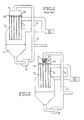
- an evaporator such as the one depicted in Figure 1 continuously circulates the slurry or solution from the lower reservoir 14, through the recirculating means 16, back to the upper reservoir 12.
- the slurry or solution repeatedly passes through the heat exchange tubes 10, where solvent is evaporated, leaving a more concentrated slurry or solution.
- the separation chamber 24 includes a plurality of apertures 32 which are sized to separate solid particles from liquid.
- Each chamber aperture 32 is of a "critical size.”
- the critical size may vary from system to system but should be equal to or smaller than the apertures downstream of the separation chamber and upstream of the heat exchange tubes.
- the chamber apertures 32 should be of such dimensions as to separate from the liquid all solid particles which are large enough to block apertures downstream of the separation chamber and upstream of the heat exchange tubes, for example, the apertures in the distributors 22.
- the slurry or solution circulating in the evaporator undergoes concentration. It is circulated from the lower reservoir 14 to the upper reservoir 12 through the recirculation conduit 20.
- the separation chamber 24 receives the recirculated slurry or solution from the outlet 27 of the recirculation conduit.
- the slurry or solution undergoes physical separation, whereby solid particles which are larger than the critical size are separated from the liquid, and a substantial portion of the liquid component exits the separation chamber through the chamber apertures 32.
- the exiting liquid enters the upper reservoir exterior of the separation chamber and then enters the heat exchange tubes 10 where it is further concentrated. Solid particles which are larger than the critical size and will not pass through the chamber apertures 32 exit the separation chamber through the chamber outlet 34 into the bypass conduit 26. The solid particles then pass directly to one of the heat exchange tubes 10 into which the bypass conduit is fitted for travel to the lower reservoir 14.
- the separation chamber 24 also helps to reduce the size of the solid particles through turbulence and impact of the solid particles against the wall of the separation chamber. When the size of the solid particles is sufficiently reduced, the solid particles will no longer cause clogging problems in the evaporator.
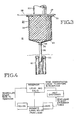
- the present invention also includes a method for selectively controlling the flow of solid particles within the evaporator.
- the following discussion of the method of the present invention is better understood with reference to the flow chart shown in Figure 4.
- a second step in the method is to recirculate the separated solid particles back to the reservoir containing the slurry or solution.
- this step of recirculation is achieved by washing the solid particles through a conduit with the aid of some of the liquid from the slurry or solution.
- a third step in the method is to direct the separated liquid to the heat exchange tubes to the evaporator.
- the liquid may contain solid particles; however, they will all be of a size smaller than the critical size and hence will not create blockage problems in the distributors or heat exchange tubes. Within the heat exchange tubes, the liquid undergoes concentration.
- a final step in the method is to direct the concentrated liquid back to the reservoir containing the slurry or solution where it is again mixed with the solids which were removed in the first step.
- the method of the present invention provides for continual circulation of solid particles, and does not provide for a building up of solid particles at any point in the system, such as would a conventional filter.
- the solid particles are constantly separated from the liquid and recirculated, at least a portion of them will decrease in size as a result of the turbulence, and will pose less of a clogging problem.
Landscapes
- Engineering & Computer Science (AREA)
- Chemical & Material Sciences (AREA)
- Organic Chemistry (AREA)
- Environmental & Geological Engineering (AREA)
- Water Supply & Treatment (AREA)
- Hydrology & Water Resources (AREA)
- Life Sciences & Earth Sciences (AREA)
- Physics & Mathematics (AREA)
- Thermal Sciences (AREA)
- Mechanical Engineering (AREA)
- General Engineering & Computer Science (AREA)
- Chemical Kinetics & Catalysis (AREA)
- Vaporization, Distillation, Condensation, Sublimation, And Cold Traps (AREA)
- Physical Or Chemical Processes And Apparatus (AREA)
Applications Claiming Priority (2)
| Application Number | Priority Date | Filing Date | Title |
|---|---|---|---|
| US198325 | 1980-10-20 | ||
| US07/198,325 US5000821A (en) | 1988-05-25 | 1988-05-25 | Apparatus for controlling solid particle flow in an evaporator |
Publications (2)
| Publication Number | Publication Date |
|---|---|
| EP0343531A1 true EP0343531A1 (de) | 1989-11-29 |
| EP0343531B1 EP0343531B1 (de) | 1994-08-03 |
Family
ID=22732911
Family Applications (1)
| Application Number | Title | Priority Date | Filing Date |
|---|---|---|---|
| EP89109063A Expired - Lifetime EP0343531B1 (de) | 1988-05-25 | 1989-05-19 | Verdampfer mit einer Vorrichtung zur Kontrolle der Strömung von Festteilchen |
Country Status (7)
| Country | Link |
|---|---|
| US (1) | US5000821A (de) |
| EP (1) | EP0343531B1 (de) |
| JP (1) | JP2685578B2 (de) |
| AT (1) | ATE109555T1 (de) |
| AU (1) | AU610976B2 (de) |
| CA (1) | CA1316098C (de) |
| DE (1) | DE68917207T2 (de) |
Cited By (7)
| Publication number | Priority date | Publication date | Assignee | Title |
|---|---|---|---|---|
| AU610976B2 (en) * | 1988-05-25 | 1991-05-30 | Resources Conservation Company | Apparatus for controlling solid particle flow in an evaporator |
| WO1995013991A1 (en) * | 1993-11-15 | 1995-05-26 | Eka Nobel Ab | Method for purifying process water from pulp manufacture |
| EP0748771A3 (de) * | 1995-06-16 | 1997-06-04 | Eka Nobel Ab | Verfahren zur Verdampfung von Abfallwasser |
| FR2751736A1 (fr) * | 1996-07-29 | 1998-01-30 | Tami Ind | Dispositif pour fragmenter des elements heterogenes d'un milieu fluide destine a circuler a l'interieur d'un appareil echangeur et installation en faisant application |
| FR2763118A1 (fr) * | 1997-05-09 | 1998-11-13 | Packinox Sa | Dispositif d'injection de fluides sous pression dans un echangeur thermique a plaques et procede de nettoyage d'un tel dispositif d'injection |
| WO2013182596A1 (de) * | 2012-06-08 | 2013-12-12 | Bma Braunschweigische Maschinenbauanstalt Ag | Fallstromverdampfer |
| CN109350977A (zh) * | 2018-11-02 | 2019-02-19 | 清华大学 | 蒸汽减压装置及工作方法 |
Families Citing this family (3)
| Publication number | Priority date | Publication date | Assignee | Title |
|---|---|---|---|---|
| EP1079194B1 (de) * | 1999-08-23 | 2004-01-21 | Nippon Shokubai Co., Ltd. | Verfahren zur Verhinderung von Verstopfungen in einem Plattenwärmetauscher |
| US7312101B2 (en) * | 2003-04-22 | 2007-12-25 | Micron Technology, Inc. | Packaged microelectronic devices and methods for packaging microelectronic devices |
| US11306971B2 (en) * | 2018-12-13 | 2022-04-19 | Applied Materials, Inc. | Heat exchanger with multistaged cooling |
Citations (4)
| Publication number | Priority date | Publication date | Assignee | Title |
|---|---|---|---|---|
| CH466221A (de) * | 1968-01-16 | 1968-12-15 | Sulzer Ag | Fallstromverdampfer, insbesondere für Rektifizierkolonnen |
| US3425083A (en) * | 1965-07-12 | 1969-02-04 | Alfa Laval Ab | Apparatus for automatically cleaning an endless pipe |
| DE1692967A1 (de) * | 1968-03-15 | 1971-08-05 | Buckau Wolf Maschf R | Fallstromverdampfer |
| US4764254A (en) * | 1987-05-21 | 1988-08-16 | Rosenblad Corporation | Falling film liquor heater having a screen to prevent clogging of a liquid distributing tray |
Family Cites Families (36)
| Publication number | Priority date | Publication date | Assignee | Title |
|---|---|---|---|---|
| US470060A (en) * | 1892-03-01 | The norbis feters co | ||
| US521974A (en) * | 1894-06-26 | Cooper | ||
| US548986A (en) * | 1895-10-29 | hewitt | ||
| US351795A (en) * | 1886-11-02 | Vacuum evaporating apparatus | ||
| US774201A (en) * | 1902-10-06 | 1904-11-08 | Herbert Robischon | Catch-basin for sink-outlets. |
| US898147A (en) * | 1906-08-21 | 1908-09-08 | Erich Von Seemen | Evaporator. |
| US1028737A (en) * | 1911-08-22 | 1912-06-04 | Kestner Evaporator Company | Process of evaporation and apparatus therefor. |
| US1191108A (en) * | 1915-05-13 | 1916-07-11 | Kestner Evaporator Company | Evaporator. |
| US2182428A (en) * | 1935-11-11 | 1939-12-05 | Fladmark Erling | Method of recovering the solids from pulp mill waste liquors |
| US2199320A (en) * | 1936-09-30 | 1940-04-30 | Juge Sergius Von Le | Evaporator for production of high-grade distillate |
| US2512938A (en) * | 1945-07-20 | 1950-06-27 | Roy O Henszey | Evaporator and separator |
| US2583364A (en) * | 1949-07-01 | 1952-01-22 | Blaw Knox Co | Apparatus for supplying and distributing liquids |
| US2764233A (en) * | 1950-07-27 | 1956-09-25 | Minute Maid Corp | Apparatus for concentrating citrus juices or the like |
| US2800307A (en) * | 1954-06-04 | 1957-07-23 | Stratford Eng Corp | Apparatus for controlling temperature change of blends of fluids or fluids and finely divided solids |
| US2993884A (en) * | 1958-02-06 | 1961-07-25 | Ciba Ltd | Metal complexes of monoazo-dyestuffs |
| US3056831A (en) * | 1958-04-25 | 1962-10-02 | Stratford Eng Corp | Sulfur trioxide sulfonation method |
| US3192130A (en) * | 1960-02-08 | 1965-06-29 | Jr John E Pottharst | Forced circulation evaporator |
| US2998060A (en) * | 1960-08-03 | 1961-08-29 | Albert W Eckstrom | High temperature method and evaporator for concentrating solutions |
| US3177129A (en) * | 1961-07-03 | 1965-04-06 | Halcon International Inc | Distillation column and reboiler |
| US3292999A (en) * | 1963-04-29 | 1966-12-20 | Chicago Bridge & Iron Co | Crystallizer with baffled recirculation flow |
| DE2212816C3 (de) * | 1972-03-16 | 1974-12-12 | Wiegand Karlsruhe Gmbh, 7505 Ettlingen | Vorrichtung zur gleichmäßigen Verteilung einzudampfender Flüssigkeit in einem Fallstromverdampfer |
| US3819053A (en) * | 1972-10-02 | 1974-06-25 | Gen Electric | Waste treatment system |
| DE2254677C2 (de) * | 1972-11-08 | 1975-02-13 | Ludwig Taprogge Reinigungsanlagen Fuer Roehren-Waermeaustauscher, 4034 Angermund | Einrichtung zum Aussortieren von im Kühlwasserkreislauf eines Kondensators mitgeführten abgeriebenen Reinigungskugeln |
| US3933576A (en) * | 1973-05-17 | 1976-01-20 | Whiting Corporation | Evaporation of radioactive wastes |
| US3880702A (en) * | 1973-06-29 | 1975-04-29 | Boris Alexandrovich Troshenkin | Film type evaporator |
| CA1013665A (en) * | 1974-01-02 | 1977-07-12 | Hooker Chemicals And Plastics Corp. | Evaporation apparatus |
| US3976430A (en) * | 1974-08-05 | 1976-08-24 | Hooker Chemicals & Plastics Corporation | Forced circulation cooling crystallizer |
| DE2725119C2 (de) * | 1977-06-03 | 1979-06-28 | Ulrich Dr.-Ing. 5100 Aachen Regehr | Separatorvorrichtung für Eindampfanlagen |
| US4248296A (en) * | 1979-08-07 | 1981-02-03 | Resources Conservation Company | Fluid distributor for condenser tubes |
| JPS5713029A (en) * | 1980-06-30 | 1982-01-23 | Hitachi Ltd | Washing sponge ball selector |
| US4288285A (en) * | 1980-07-28 | 1981-09-08 | Evaporator Technology Corporation | Apparatus for forming a vortex |
| JPS5840497A (ja) * | 1981-09-04 | 1983-03-09 | Hitachi Ltd | 洗浄体選別器 |
| US4734269A (en) * | 1985-06-11 | 1988-03-29 | American Hospital Supply Corporation | Venous reservoir bag with integral high-efficiency bubble removal system |
| US4683025A (en) * | 1986-02-10 | 1987-07-28 | The Graver Company | Method and apparatus to convert a long tube vertical evaporator to a falling film evaporator |
| US4828717A (en) * | 1988-04-14 | 1989-05-09 | Arkay Corporation Of Wisconsin | Device and method for reducing volume of aqueous waste effluents |
| US5000821A (en) * | 1988-05-25 | 1991-03-19 | Resources Conservation Company | Apparatus for controlling solid particle flow in an evaporator |
-
1988
- 1988-05-25 US US07/198,325 patent/US5000821A/en not_active Expired - Lifetime
-
1989
- 1989-01-24 CA CA000589057A patent/CA1316098C/en not_active Expired - Lifetime
- 1989-02-01 AU AU28977/89A patent/AU610976B2/en not_active Expired
- 1989-04-21 JP JP1103319A patent/JP2685578B2/ja not_active Expired - Lifetime
- 1989-05-19 DE DE68917207T patent/DE68917207T2/de not_active Expired - Lifetime
- 1989-05-19 AT AT89109063T patent/ATE109555T1/de not_active IP Right Cessation
- 1989-05-19 EP EP89109063A patent/EP0343531B1/de not_active Expired - Lifetime
Patent Citations (4)
| Publication number | Priority date | Publication date | Assignee | Title |
|---|---|---|---|---|
| US3425083A (en) * | 1965-07-12 | 1969-02-04 | Alfa Laval Ab | Apparatus for automatically cleaning an endless pipe |
| CH466221A (de) * | 1968-01-16 | 1968-12-15 | Sulzer Ag | Fallstromverdampfer, insbesondere für Rektifizierkolonnen |
| DE1692967A1 (de) * | 1968-03-15 | 1971-08-05 | Buckau Wolf Maschf R | Fallstromverdampfer |
| US4764254A (en) * | 1987-05-21 | 1988-08-16 | Rosenblad Corporation | Falling film liquor heater having a screen to prevent clogging of a liquid distributing tray |
Non-Patent Citations (1)
| Title |
|---|
| PATENT ABSTRACTS OF JAPAN, vol. 9, no. 223 (M-411)[1946], 10th September 1985; & JP-A-60 80 081 (HITACHI SEISAKUSHO K.K.) 07-05-1985 * |
Cited By (12)
| Publication number | Priority date | Publication date | Assignee | Title |
|---|---|---|---|---|
| AU610976B2 (en) * | 1988-05-25 | 1991-05-30 | Resources Conservation Company | Apparatus for controlling solid particle flow in an evaporator |
| WO1995013991A1 (en) * | 1993-11-15 | 1995-05-26 | Eka Nobel Ab | Method for purifying process water from pulp manufacture |
| EP0748771A3 (de) * | 1995-06-16 | 1997-06-04 | Eka Nobel Ab | Verfahren zur Verdampfung von Abfallwasser |
| US5792313A (en) * | 1995-06-16 | 1998-08-11 | Eka Nobel Ab | Method for evaporating process wastewater |
| FR2751736A1 (fr) * | 1996-07-29 | 1998-01-30 | Tami Ind | Dispositif pour fragmenter des elements heterogenes d'un milieu fluide destine a circuler a l'interieur d'un appareil echangeur et installation en faisant application |
| EP0821997A1 (de) * | 1996-07-29 | 1998-02-04 | T.A.M.I. Industries | Vorrichtung zum Zerkleinern von verschiedenenartigen Bestandteilen eines flüssigen Mediums, das in einem Filtrationsmodul strömen wird |
| US6228261B1 (en) | 1996-07-29 | 2001-05-08 | Societe Anonyme: T.A.M.I. Industries | Appliance for fragmenting heterogeneous elements of a fluid medium for circulation in a filter module |
| FR2763118A1 (fr) * | 1997-05-09 | 1998-11-13 | Packinox Sa | Dispositif d'injection de fluides sous pression dans un echangeur thermique a plaques et procede de nettoyage d'un tel dispositif d'injection |
| EP0877222A3 (de) * | 1997-05-09 | 2000-02-23 | Packinox | Anlage zum Druckspritzen von Fluiden in einem Plattenwärmetauscher und Verfahren zur Reinigung dieser Druckspritzanlage |
| US6196301B1 (en) | 1997-05-09 | 2001-03-06 | Packinox | Device for injecting pressurized fluids into a multiplate heat exchanger and method of cleaning such an injection device |
| WO2013182596A1 (de) * | 2012-06-08 | 2013-12-12 | Bma Braunschweigische Maschinenbauanstalt Ag | Fallstromverdampfer |
| CN109350977A (zh) * | 2018-11-02 | 2019-02-19 | 清华大学 | 蒸汽减压装置及工作方法 |
Also Published As
| Publication number | Publication date |
|---|---|
| CA1316098C (en) | 1993-04-13 |
| EP0343531B1 (de) | 1994-08-03 |
| DE68917207D1 (de) | 1994-09-08 |
| JP2685578B2 (ja) | 1997-12-03 |
| ATE109555T1 (de) | 1994-08-15 |
| DE68917207T2 (de) | 1994-11-24 |
| AU610976B2 (en) | 1991-05-30 |
| AU2897789A (en) | 1989-11-30 |
| US5000821A (en) | 1991-03-19 |
| JPH01317501A (ja) | 1989-12-22 |
Similar Documents
| Publication | Publication Date | Title |
|---|---|---|
| US5116473A (en) | Apparatus for controlling solid particle flow in an evaporator | |
| US3731802A (en) | Liquid separator | |
| DE69016384T2 (de) | Hydrodynamischer Rauchgaswäscher. | |
| DE3783227T2 (de) | System und zufuehrungsleitung fuer ein brennstoffzellenkuehlmittel. | |
| US4861472A (en) | Apparatus for filtration of a suspension | |
| US5000821A (en) | Apparatus for controlling solid particle flow in an evaporator | |
| SE429128B (sv) | Forfarande for separering av fororeningar i vattensuspensioner eller -emulsioner | |
| DE2229792A1 (de) | Verfahren und Vorrichtung zur Reinigung von Gasen | |
| JP6437857B2 (ja) | 沈殿池 | |
| DE69205895T2 (de) | Vorrichtung und Verfahren für das Regenerieren von körnigen Medien. | |
| CN109364575B (zh) | 一种污水处理的多级过滤系统及污水过滤方法 | |
| EP0412173A1 (de) | Verfahren und Anlage zur Aufbereitung und Reinigung von Abwasser | |
| US4399034A (en) | Liquid filtering apparatus | |
| DE112014001959T5 (de) | Zentrifuge mit einer Wasserablasskonstruktion und ein Reinigersystem, das diese verwendet | |
| DE2441384A1 (de) | Zwangsumlaufverdampfer | |
| DE3321440C2 (de) | ||
| DE2806109A1 (de) | Vorrichtung zum reinigen von fluessigkeiten | |
| DE2704116A1 (de) | Verfahren und vorrichtung zum sammeln und ausscheiden von feststoffen aus schlamm-massen | |
| US3610417A (en) | System for preventing sludge formation in a cooling tower reservoir | |
| DE60003422T2 (de) | Vorrichtung zur reinigung von flüssigkeitsgemischen und/oder zum waschen von gasen | |
| DE2800668B2 (de) | Vorrichtung zum Auswaschen von Farbnebel aus der Abluft von Lackieranlagen | |
| SK280650B6 (sk) | Zariadenie na extrakciu rašeliny | |
| DE1517391B2 (de) | Vorrichtung zum klaeren von wasser | |
| DE19729802A1 (de) | Verfahren und Vorrichtung zum Trennen von Stoffen und Leiteinrichtung hierfür | |
| CN113713509B (zh) | 一种高温汽水过滤单元及组合式高温汽水过滤装置 |
Legal Events
| Date | Code | Title | Description |
|---|---|---|---|
| PUAI | Public reference made under article 153(3) epc to a published international application that has entered the european phase |
Free format text: ORIGINAL CODE: 0009012 |
|
| AK | Designated contracting states |
Kind code of ref document: A1 Designated state(s): AT BE CH DE ES FR GB GR IT LI LU NL SE |
|
| 17P | Request for examination filed |
Effective date: 19900213 |
|
| 17Q | First examination report despatched |
Effective date: 19901011 |
|
| GRAA | (expected) grant |
Free format text: ORIGINAL CODE: 0009210 |
|
| AK | Designated contracting states |
Kind code of ref document: B1 Designated state(s): AT BE CH DE ES FR GB GR IT LI LU NL SE |
|
| PG25 | Lapsed in a contracting state [announced via postgrant information from national office to epo] |
Ref country code: IT Free format text: LAPSE BECAUSE OF FAILURE TO SUBMIT A TRANSLATION OF THE DESCRIPTION OR TO PAY THE FEE WITHIN THE PRE;WARNING: LAPSES OF ITALIAN PATENTS WITH EFFECTIVE DATE BEFORE 2007 MAY HAVE OCCURRED AT ANY TIME BEFORE 2007. THE CORRECT EFFECTIVE DATE MAY BE DIFFERENT FROM THE ONE RECORDED.SCRIBED TIME-LIMIT Effective date: 19940803 Ref country code: LI Effective date: 19940803 Ref country code: BE Effective date: 19940803 Ref country code: AT Effective date: 19940803 Ref country code: CH Effective date: 19940803 Ref country code: NL Effective date: 19940803 Ref country code: ES Free format text: THE PATENT HAS BEEN ANNULLED BY A DECISION OF A NATIONAL AUTHORITY Effective date: 19940803 Ref country code: GR Free format text: LAPSE BECAUSE OF FAILURE TO SUBMIT A TRANSLATION OF THE DESCRIPTION OR TO PAY THE FEE WITHIN THE PRESCRIBED TIME-LIMIT Effective date: 19940803 |
|
| REF | Corresponds to: |
Ref document number: 109555 Country of ref document: AT Date of ref document: 19940815 Kind code of ref document: T |
|
| REF | Corresponds to: |
Ref document number: 68917207 Country of ref document: DE Date of ref document: 19940908 |
|
| ET | Fr: translation filed | ||
| REG | Reference to a national code |
Ref country code: CH Ref legal event code: PL |
|
| NLV1 | Nl: lapsed or annulled due to failure to fulfill the requirements of art. 29p and 29m of the patents act | ||
| EAL | Se: european patent in force in sweden |
Ref document number: 89109063.1 |
|
| PG25 | Lapsed in a contracting state [announced via postgrant information from national office to epo] |
Ref country code: LU Free format text: LAPSE BECAUSE OF NON-PAYMENT OF DUE FEES Effective date: 19950531 |
|
| PLBE | No opposition filed within time limit |
Free format text: ORIGINAL CODE: 0009261 |
|
| STAA | Information on the status of an ep patent application or granted ep patent |
Free format text: STATUS: NO OPPOSITION FILED WITHIN TIME LIMIT |
|
| 26N | No opposition filed | ||
| REG | Reference to a national code |
Ref country code: GB Ref legal event code: IF02 |
|
| PGFP | Annual fee paid to national office [announced via postgrant information from national office to epo] |
Ref country code: DE Payment date: 20080630 Year of fee payment: 20 Ref country code: SE Payment date: 20080529 Year of fee payment: 20 |
|
| PGFP | Annual fee paid to national office [announced via postgrant information from national office to epo] |
Ref country code: GB Payment date: 20080529 Year of fee payment: 20 |
|
| REG | Reference to a national code |
Ref country code: GB Ref legal event code: PE20 Expiry date: 20090518 |
|
| EUG | Se: european patent has lapsed | ||
| PG25 | Lapsed in a contracting state [announced via postgrant information from national office to epo] |
Ref country code: GB Free format text: LAPSE BECAUSE OF EXPIRATION OF PROTECTION Effective date: 20090518 |
|
| PGFP | Annual fee paid to national office [announced via postgrant information from national office to epo] |
Ref country code: FR Payment date: 20080519 Year of fee payment: 20 |
|
| P01 | Opt-out of the competence of the unified patent court (upc) registered |
Effective date: 20230521 |